
Vision Based Surveillance System using
Low-Cost UAV
Kim Jonghun, Lee Daewoo, Cho Kyeumrae, Jo Seonyong
Kim Jungho and Han Dongin
Dept. of Aerospace Engineering, Pusan National University
Geumjung Gu, Busan, Korea
Abstract. This paper describes the development of a surveillance system in the
laboratory for small unmanned aerial vehicles (UAV). This system is an impor-
tant equipment of a mission-oriented UAV. For making a good performance on
search, this can track images and take 3-D measurement of a target as well as
acquire high quality images. Image tracking is carried out by the Kalman Filter.
The position of the target in an image and the relationship among the coordi-
nate systems of the UAV and the Camera and reference are used to solve the 3-
D position of the target in real coordinates. This paper presents the hardware
system as well as algorithm for the EOS, and then verifies the performance of
the image tracking and real-time 3-D measurement of a target’s position. Espe-
cially, to reduce the 3-D measurement error of the target, Linear Parameter
Varying (LPV) is applied to the measurement system. The performances for
their algorithms are presented in the figures in this paper.
1 Introduction
Recently, interest about UAV system has been increased. Basically, guidance and
control were researched. After UAV system had ability to make a stable performance,
some researchers are finding new algorithm to make a good result, like as neural
network, fuzzy algorithm. Others make efforts to get a satisfied result using the exact
measurement, UAV’s attitude, position and velocity and target’s position and veloci-
ty.
To get the accurate measurement about UAV and target, INS and GPS system are
being studied. Also, machine vision system is being researched, recently. Vision
system on UAV is necessary to acquire information of target and operate missions,
such as surveillance and rescue at mountain or ocean. For civil system, to observe fire
place at mountain is researched [1], and searching algorithm to track person or car at
the urban is studied [2].
To measure 3D position of target using monocular vision, perspective matrix is
used mostly [3]. This is easily to solve the position in image or real world with con-
sider attitude between camera and target. However, algebra equations from perspec-
Jonghun K., Daewoo L., Kyeumrae C., Seonyong J., Jungho K. and Dongin H. (2009).
Vision Based Surveillance System using Low-Cost UAV.
In Proceedings of the 3rd International Workshop on Intelligent Vehicle Controls & Intelligent Transportation Systems, pages 143-148
Copyright
c
SciTePress
tive matrix are under determinant. To get the answer about the position, we need to
know some points.
On the contrast, we can know distance between UAV and ground using GIS. If al-
titude of UAV and target in ground is known, perspective matrix is not necessary. We
can acquire position through only relative equations about image and real world
coordinate system. In this paper, nonlinear filter is employed to estimate 3-D position
of target. Filter gains of this are derived by linear parametric varying system of error
dynamics. This algorithm will be introduced and verified at chapter 4. Chapter 2
explains guidance/control, and hardware system on our UAV. Chapter 3 represents
vision system.
2 UAV System
2.1 System Description
In this paper, the UAV system was used to study and design the algorithm that will
allow image tracking and 3-D measurement of the position of the target in real space
using a monocular image. Specification of UAV, used for experiment is PNUAV that
we made ourselves, is represented in Table 1.
Table 1. Specification of PNUAV.
Wing Span 2,050mm
Wing Area
79.5 sq∙dm
Empty Weight 3,300 g
Fuselage 1,633 mm
Class of Engine 19.96 CC
The flight control system consists of the main controller, GPS, Attitude Heading
Reference System (AHRS), actuator, communication system, power supply and
ground control system (GCS).
The AHRS offer the plane’s attitude and position information to the sub-processor,
that is, the main processor, which calculates algorithm to control the surface of plane
directly via the actuator. Also, the states of plane can be observed at the ground sta-
tion via the communication system, which can be used to transmit the control com-
mand to UAV from ground station when needed.
The GPS receiver that was used has comparative high performance and authorita-
tiveness by altitude range in 18km and speed range in nearly 1850km/h that measur-
ing is possible, produced by NovAtel Inc. Data output mode used NMEA, and used
the GSA protocol which supplied position information and GGA protocol which
included satellite information.
The RF data modem is used as communication device that receive and confirm all
sensor data of UAV, when UAV is in flight. The antenna in the modem greatly af-
fects the communication equipments. A directional antenna has a big gain value, but
the UAV uses non-directional dipole antenna to considering the UAV has wide active
area.
144
2.2 Guidance & Control
The UAV has various waypoints, where it can obtain images and drop the something
(like a bomb), so the correct/accurate passing of the waypoint is a very important
performance index of the operation of the UAV. Point navigation guidance is used in
the flight test. The guidance logic is based on the difference between the line of sight
angle, which is measured from the reference axis to the waypoint, and the UAV's
heading angle, which is set as an error, that is made to be zero. In a straight level
flight, the angle of the velocity vector and the LOS angle are used for lateral direction
control. The longitudinal direction guidance uses proportional control that is based on
the difference between the present altitude and the target altitude.
When only the P controller is used, the overshoot increases. On the other hand, if
the PID controller is used, the steady state error will be reduced. However, I gain has
less influence on flight performance and the computation load is added to the main
processor. For this reason, the PD controller was used. It used the fluxion of angle, so
it makes different to the weight of control. That is, the effect of fluxion is small when
the flight to straight. However, if the LOS angle grows, the control value will increase,
and then the UAV will show a fast response.
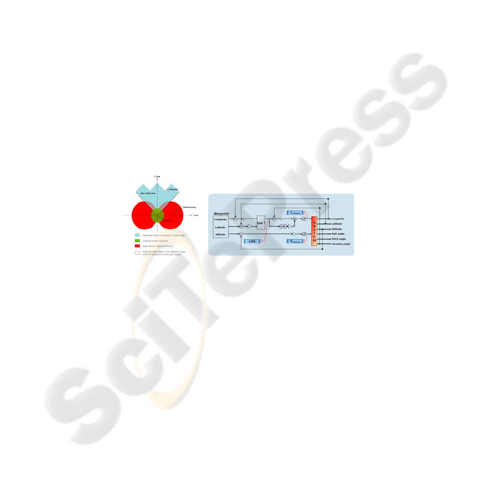
When the UAV passes a waypoint, without converging, the waypoint is in the
minimum turning range. The UAV will fly, turning many times. Therefore, in this
case, the UAV must escape the minimum range to follow the former control com-
mand. Fig. 1, it shows the geometric relations of UAV’s flight range and the way-
point.
Fig. 1. control range at body axis (left), design PD controller (right).
3 Vision System
The vision system of PNUAV consists of a transmission system, gimbal controller,
and image acquisition system. The gimbal controller provides the control input for
pan and tilt movements. Camera zoom and focus are also controlled by the gimbal
controller.
On the ground, two ground control system (GCS) operate to command and acquire
information. One is the data GCS that can show the state of the UAV and command
the UAV to fly on waypoint or to achieve missions. The other is the vision GCS.
The vision GCS is built using LabVIEW. This provides the image from PNUAV,
and has a command window where the user can input the angle of gimbal’s pan and
tilt or other control inputs. Command from the user input is transmitted to gimbal
145
controller through data GCS. Data GCS sends control inputs to move the vision sys-
tem, as well as to maneuver the UAV.
3.1 Derivation of Arithmetic Range
In this paper, the dynamic relationship among the UAV, vision system, and GCS is
derived. The 3-D position of the target is calculated from a monocular image as
shown in Equations (1) and (2).
Z
X
fx =
(1)
Z
Y
fy =
(2)
Where, is focal length,
(
is the position in the image, and
f
)
yx,
(
)
ZYX ,,
is the
position in the real spacer. If the position along Z-axis is known, the 3-D information
can be determined.
However, the 3-D information from Equations (1) and (2) is the result with respect
to the camera frame. To transfer the coordinates from the camera to the reference
frame, the attitudes of the camera and UAV are necessary. The attitude of a UAV
with respect to a body fixed coordinate, is known as an onboard AHRS.
To get the position along Z, we assume the following ; 1) target is on a flat
plane(zero altitude), and 2) the attitudes of UAV and camera can be measured. Using
directional vector from the camera axes, the attitudes of the UAV and camera are
obtained. A linear equation on 3-D is made from a unit directional vector from the
camera to the target at zero altitude. The distance along Z-axis can be derived from a
linear equation. Equations (3) and (4) represent the unit directional vector and the
distance along Z, respectively [4].
(
)
(
)
[
]
T
V
C
i
V
TTl 100
11 −−
=
r
(3)
()
2
2
3
2
2
3
1
i
v
i
v
i
v
z
l
zl
l
zl
m +
⎟
⎟
⎠
⎞
⎜
⎜
⎝
⎛
+
⎟
⎟
⎠
⎞
⎜
⎜
⎝
⎛
=
r
(4)
Where, is the unit directional vector between the camera and the target, is
the Euler transformation matrix of the UAV attitude with respect to the reference, and
is the Euler transformation matrix of the camera attitude with respect to the UAV.
is the altitude of the UAV with respect to the reference frame.
l
r
i
V
T
V
C
T
i
v
z
3.2 3-D Measurement using LPV
Method using arithmetic derivation can cause an error because of sensor noise. The
result of this algorithm depends on the attitudes of the UAV and camera. This type of
error is made at initial installation and by drift.
146
To reduce the error caused by the attitude sensor, the filter, which was studied, is
applied on the 3-D measurement using monocular vision. The basic and popular filter
is the Kalman filter for the estimation of the 3-D position. However, the dynamics
derived to measure 3-D position of the target by monocular vision has nonlinearity.
Although the Kalman filter can be applied on a nonlinear system, system error can be
caused by the assumption of linearization. Therefore, the extended Kalman filter or a
particle filter can be more effective. However, these filters are too complex to design
and run. LPV, on the other hand, can be applied easily on the 3-D measurement of a
target, and is effective on nonlinear systems.
General EOS uses a laser range finder or other measurement equipment to measure
the distance between the camera and the target. Such additional equipment increases
the weight and complexity of the system. Thus
m
r
, which is derived for deciding the
distance using the attitude and position of the camera and UAV, is used in this paper.
To improve the result in a asynchronous system, a modified nonlinear filter is de-
rived. In [5], this filter is used on an out-of-sight problem. However, in this paper,
filter is modified for an asynchronous system. Equation (5) represents the modified
nonlinear filter.
()
()
⎪
⎪
⎪
⎩
⎪
⎪
⎪
⎨
⎧
=
−=
−++−=
−
−
)
ˆ
(
ˆ
))
ˆ
()(
ˆ
(
ˆ
))
ˆ
()(
ˆ
(
ˆ
1
2
1
1
c
i
cc
mcc
c
itg
mcc
c
itgc
PTP
yPgPHTskV
dt
d
yPgPHTskVVP
dt
d
ψθ
ψθ
(5)
Where, and are the position and measurement of the target, respectively.
is the same as
(
. is the Jacobian matrix of . In Equation
(5), data asynchronous means that non receiving UAV information and out-of-sight
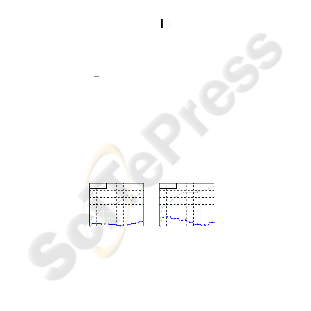
of target in image. Fig. 2 shows the results obtained with the modified nonlinear filter.
Fig. 2, which are obtained from the modified filter system show good performance.
The average distance error of the arithmetic method is about 94m, whereas the LPV is
about 10m.
tg
V
m
y
g
ϕθ
m
y
)(
c
P
)
ˆ
(
c
PH
)
ˆ
(
c
Pg
ϕθ
0 5 10 15 20 25 30 35 40
0
10
20
30
40
50
60
Error along X-axis
Epoch
Error (m)
LPV
Arithmetical
0 5 10 15 20 25 30 35 40
0
20
40
60
80
100
120
Error along Y-axis
Epoch
Error (m)
LPV
Arithmetical
Fig. 2. Error along X-axis (left), Error along Y-axis (right).
147

4 Conclusions
This paper describes the development of a laboratory level vision system for small
UAVs to measure the 3-D position of a target from a monocular image, acquired from
the vision system on a UAV.
The Kalman filter is used to track the target in the image in real time. Through the
algorithm for 3-D measurement, the 3-D position of the target can be estimated in the
real space based on the target’s position in the image, position and attitude of the
UAV, and the attitude of the camera.
To make a simple vision system, the range between UAV and target is determined
by arithmetic method. This range is used for a nonlinear filter system, derived from
LPV and LMI. Since a nonlinear filter do not considered synchronism in receiving
data, performance is similar with arithmetic method.
A modified nonlinear filter was suggested to prevent this problem. We can verify
that the modified nonlinear filter is effective.
Acknowledgements
This research was financially supported by the Ministry of Education, Science Tech-
nology (MEST) and Korea Industrial Technology Foundation (KOTEF) through the
Human Resource Training Project for Regional Innovation.
References
1. L. Merino, A. Ollero, J. Ferruz, J. R. Martinez-de-Dios and B. Arrue: Motion analysis and
Geo-location for aerial monitoring in the COMETS multi-UAV system. in Proc. ICAR
2003 Coimbra (2003).
2. Klas Nordberg, Patrick Doherty, Gunnar Farneback, Per-Erik Forssen, Gosta Granlund,
Anders Moe, Johan Wiklund: Vision for a UAV helicopter. Proceedings of IROS'02. work-
shop on aerial robotics (2002).
3. Milan Sonka, Vaclac Hlavac, Roger Boyle: Image Processing, Analysis, and Machine
Vision. PWS Publishing. USA (1998).
4. Jong-hun Kim, Seon-yeong Jo, Jung-ho Kim, Dae-woo Lee, Kyeum-rae Cho, Ji-hwan Shin:
Development of Laboratory Level Optical Module for Unmanned Aerial Vehicle using
LabVIEW. 2008 Conference of Korea Institute of Military Science and Technology (2008).
5. Vladimir N. Dobrokhodiv, Isaac I. Kaminer, Kevin D. Jones, and Reza Ghabcheloo: Vi-
sion-Based Tracking and Motion Estimation for Moving targets using Small UAVs. Pro-
ceedings of the 2006 American Control Conference (2006).
148
