
TRACEABILITY MECHANISM FOR ERROR LOCALIZATION IN
MODEL TRANSFORMATION
Vincent Aranega, Jean-Marie Mottu, Anne Etien and Jean-Luc Dekeyser
LIFL, University of Lille 1, France
INRIA Lille - Nord Europe, France
Keywords:
Model transformation, Error localization, Metamodels, Traceability, Tests.
Abstract:
Model Driven Engineering (MDE) introduces the model paradigm as the basis of system design. It increases
reusability in the development of complex systems. Nevertheless, with this new paradigm, traditional issues
such as system debugging or system evolution management have to be performed in a different way. Existing
techniques require to be adapted. We have shown the feasibility of traceability to solve these issues. However,
system debugging can only be undertaken if the developer trusts the compiler. In MDE, the compiler is a
transformation chain. It is hence important to test the transformations and possibly to debug them. In this
paper, we demonstrate that our traceability mechanism coupled to our error localization algorithm eases the
transformation test. Indeed, it highlights the succession of rule that leads to a faulty output element. This
approach is illustrated in the context of embedded system development.
1 INTRODUCTION
Model Driven Engineering (MDE) proposes to use
models as main artifacts in the life cycle of com-
plex systems. Thus model transformation becomes
the skeleton of the system development by helping to
shift from a model to another or to re-factor a model.
The outputs of a transformation can also be the inputs
of another one defining a chain.
During the development phase of complex system
various types of errors can be encountered: those con-
cerning the compiler and those concerning the system
itself. In an MDE approach, the first refer to the def-
inition of the transformation whereas the last corre-
spond to the generated system. Furthermore, as sys-
tems may evolve, they imply changes in different sub-
parts to lead to a new stable configuration. Even if
these issues are common to any system, they require
a specific management when a model driven develop-
ment approach is used.
Traceability is potentially relevant to help design-
ers to solve these issues. It is usually used to link the
requirements to the implementation artifacts. How-
ever, traceability allows one to establish degrees of
relationship between products of a development pro-
cess, especially products bound by a predecessor-
successor or master-subordinate relationship (IEEE,
1991). Regarding MDE and more specifically model
transformations, the traceability mechanism links el-
ements of different models in order to specify ele-
ments useful to generate others. Those links can also
be used to analyze impacts of model evolutions onto
other models in the transformations chain. Finally, it
is reasonable to consider traceability as a bridge be-
tween the business and the transformation world, if
the transformation rules are explicitly associated to
the links. Business is so materialized by the models
useful to generate the system.
We have already defined a traceability algorithm
based on two metamodels (Glitia et al., 2008). One
captures the trace relative to a single transforma-
tion. The other manages the relationships all along
the transformation chain. These metamodels are rich
enough to support algorithms dedicated to the res-
olution of the previously cited issues. In (Glitia
et al., 2008), this traceability mechanism underlines
links between an element and the elements of nu-
merous models involved in its generation. This helps
both system debugging and alternative design explo-
rations. In this paper, we focus on error localization
in model transformation and we propose an algorithm
based on our traceability metamodels. From a given
generated element, our approach identifies the rule
sequence of each intermediate transformation of the
complete transformation chain. Tests identify incor-
rect parts of the produced model. Then, the erroneous
66
Aranega V., Mottu J., Etien A. and Dekeyser J. (2009).
TRACEABILITY MECHANISM FOR ERROR LOCALIZATION IN MODEL TRANSFORMATION.
In Proceedings of the 4th International Conference on Software and Data Technologies, pages 66-73
DOI: 10.5220/0002264700660073
Copyright
c
SciTePress

rule which causes this failure is detected. We have
successfully applied this algorithm on a case study.
This paper is organized as follows. Section 2
presents existing traceability solutions in MDE. Sec-
tion 3 gives different ways to exploit trace. In sec-
tion 4, the trace metamodels are introduced and the
use of the trace models for faulty transformation rules
identification is described. Section 5 illustrates our
approach with a case study based on a QVT transfor-
mation. Finally, we conclude the paper and suggest
future works in section 6.
2 RELATED WORK
In MDE, many solutions for traceability are proposed
in the literature (Galvao and Goknil, 2007), (Reshef
et al., 2006), each of them responding to specific
needs of projects.
MDE has as main principle that everything is a
model, so the trace information is stored as mod-
els (Jouault, 2005). Classically, two main approaches
exist. The first focuses on the addition of trace in-
formation on the source or target model (Velegrakis
et al., 2005). The major drawback of this solution is
that it pollutes the models with additional informa-
tion and it requires the metamodels adaptation in or-
der to take into account traceability. However it pro-
duces the most comprehensive traces. The second so-
lution focuses on the storage of the trace as an inde-
pendent model. Using a separate trace model with a
specific semantics has the advantage of keeping trace
information independent of original models (Jouault,
2005). To deal with the advantage of these two tech-
niques, a solution consist on the possibility to merge
on-demand the trace model with the transformation
source or target model (Kolovos et al., 2006).
Collecting the trace information can be easily per-
formed during the transformation execution since this
only incurs a small cost (Vanhooff et al., 2007). In-
deed the trace model is thus viewed as an additional
target model. For this reason, trace generation could
be manually implemented in transformations to pro-
duce an additional trace target model or it can be sup-
ported by the transformation engine (Czarnecki and
Helsen, 2006). In (Jouault, 2005), an automatic gen-
eration of trace code into rule code is presented, based
on the fact that transformation programs are mod-
els that could be transformed into another model that
contains trace code. Nevertheless, these solutions im-
pose to inject code in transformation rules or trans-
formation engine. To remain the less intrusive as pos-
sible, Amar et al. propose another technique using
aspect programming (Amar et al., 2008). Regrettably,
for the moment, this solution cannot be used with ev-
ery transformation languages.
Once the trace is generated, the main interest for
the user is to have access to the information he needs.
However, in case of transformations chain, the trace
models relying only on the two concepts Element and
Link, which are produced during the transformations,
are not enough. One solution is to add the concept of
Step, referring to a transformation, in the trace model
such as in the trace mechanism of Kermeta (Falleri
et al., 2006). Traceability links are gathered by step
(i.e. by transformation) what thus allows to manage
transformation chains. An other solution is to exter-
nalize the navigation between initial models and trace
models of a whole transformation chain in another
model, called megamodel. It refers to the traceabil-
ity in the large, whereas model to model transforma-
tions refer to a traceability in the small (Barbero et al.,
2007).
3 USING TRACEABILITY IN
MODEL DRIVEN
ENGINEERING
In the introduction, we identified three different is-
sues that can be encountered in the development of
complex systems: fix the system itself, fix the trans-
formations generating the system and manage the im-
pact of evolutions on the whole system. We have sug-
gested that a traceability mechanism can solve these
issues. In this section, we show that, while remain-
ing in MDE, each of these purposes requires different
traceability information.
3.1 Needed Trace Information
When an error in the generated system is found or
when an unexpected behavior is observed, the sys-
tem has to be fixed. For this purpose, the elements
of the input models that engender the (or one of the)
incorrect element(s) have to be identified. Such in-
formation are at the heart of any traceability mech-
anism and are materialized by links between source
elements and target elements. These can also be used
to analyze the impact of the input model evolutions
on the output model and to propagate these changes.
However, when the system evolves, the transforma-
tion may also evolve. To overcome this issue, the rule
engendering a traceability link must be associated to
it. Furthermore, the traceability mechanism has to be
adapted to the model driven development reality. In-
deed, complex systems do not rely on a single trans-
TRACEABILITY MECHANISM FOR ERROR LOCALIZATION IN MODEL TRANSFORMATION
67
formation but on one or several transformation chain.
Therefore traceability should support relationships all
along the chain.
As a first conclusion, we have demonstrated that
links between source and target elements are not
enough to build an efficient traceability mechanism
dedicated to system fixing and system evolution. In-
formation relative to the transformation rules and al-
lowing the navigation in the transformation chain are
required.
It can be noticed that fixing the system can be per-
formed only if we are confident in the transformations
that generate it. In the following subsection, we focus
on using traceability in transformation test and show
that information relative to the input/output elements
relationships, transformation rules and navigation in
the transformations chain are, in that case, also re-
quired.
3.2 Trace Exploitation for Model
Transformation Testing
In this subsection, we briefly present the transforma-
tion test and then we show how trace can be used in
this context.
3.2.1 Model Transformation Testing
By automating critical operations in system develop-
ment, model transformations are time and effort sav-
ing. However, they may also introduce additional er-
rors if they are faulty. Therefore, systematic and ef-
fective testing of transformations is necessary to pre-
vent the production of erroneous models.
Several problems need to be solved when tackling
model transformation testing. First, we need to de-
tect the presence of errors by observing wrong exe-
cution of the model transformation. Corresponding
challenges are efficient test data production and ob-
servation of error in the system. We then have to lo-
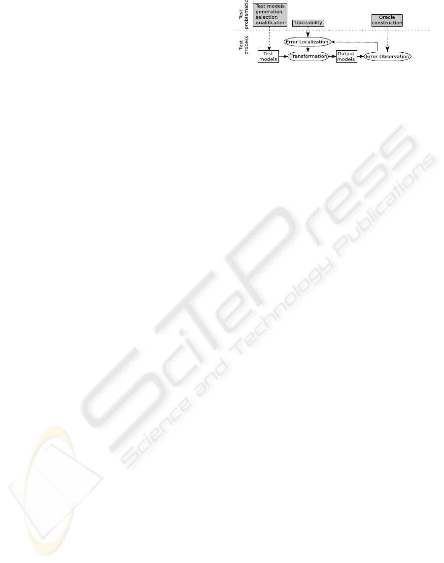
cate the error in the transformation and to fix it. Fig-
ure 1 sketches the test transformation process and as-
sociates its different parts to the corresponding test
problematics.
Efficient test data production and error observa-
tion are challenges out of this paper scope. Neverthe-
less, we briefly illustrate them. In this paper, we focus
on error localization.
Transformations manipulate models, which are
very complex data structures. This makes the prob-
lems of test data generation, selection, and qualifica-
tion, as well as error observation very difficult.
Test data generation consists in building models
conform to the input metamodel. Their number is
Figure 1: Test transformation process.
potentially infinite so the first challenge is to define
criteria for test data generation (Fleurey et al., 2007).
Then, the resulting test models set has to be qualified,
depending on their coverage of the input domain or
on their ability to detect potential errors.
Error observation relies on the detection of an
error in a model produced by the transformation.
In (Mottu et al., 2008)we proposedan approachbased
on the construction of oracles. The oracle checks
the validity of the output model resulting from the
transformation of one test model. It relies either on
properties between elements of the input and out-
put models or properties only concerning the output
model. These properties have to be formalized and
must cover the whole metamodels. Defining oracles
is difficult since human intervention is required. In-
deed, extracting information to produce oracle from
the model transformation requirements cannot be au-
tomatized.
3.2.2 Error Localization in Model
Transformation
Errors observed in the output model can concern:
wrong property value, additional/missing class, etc.
They result from errors in the transformation. Where
are they and what are they, are two questions that re-
main unanswered.
The error can be everywhere in the transforma-
tion. Its detection is easier if the search field is re-
duced to the faulty rule, i.e. the rule that creates the
incorrect element (or doesn’t create an expected ele-
ment) in the output model. Once the error localized in
the transformation, in order to fix it, the input model
elements leading to this incorrect output element have
to be identified.
Finally, due to the non exhaustiveness of test and
the complexity of building oracles, test of a single
transformation can be missed at the expense of test
of the whole transformation chain.
ICSOFT 2009 - 4th International Conference on Software and Data Technologies
68
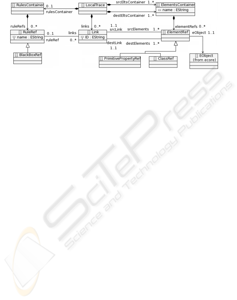
Figure 2: Local Trace Metamodel.
4 TRACEABILITY
METAMODELS DESCRIPTION
To solve the problems we want manage (e.g. system
debugging, transformation debugging, design alterna-
tive exploration...), we have defined our own trace ap-
proach (Glitia et al., 2008). This approach provides
a traceability in the small and in the large (Barbero
et al., 2007), which we refer as local and global trace-
ability respectively. It relies on two metamodels: the
Local Trace metamodel corresponding to the model
to model traceability and the Global Trace metamodel
helping in the global navigation. These two metamod-
els are completely independent from the transforma-
tion language and can even be used with various lan-
guages. Only the trace generation changes. Our trace-
ability mechanism allows users to trace elements all
along a transformation chain where each transforma-
tion may be written in different languages.
4.1 Local Trace Metamodel
The Local Trace metamodel is used to capture the
traces between the input and the output of one trans-
formation. The metamodel is based on the trace meta-
model presented in (Jouault, 2005). Figure 2 shows
the Local Trace metamodel.
The Local Trace metamodel contains two main
concepts: Link and ElementRef expressing that one
or more source elements are possibly bound to target
elements. Those concepts are the same as in (Jouault,
2005). All the other concepts have been added to pro-
vide a finer and more complete trace. In our meta-
model ElementRef is an abstract class representing
model elements that can be traced (i.e. properties
and classes). Property values referring to a primitive
types like Integer, Double, String etc. are traced using
PrimitivePropertyRef. Properties typed by a class are
traced by ClassRef.
More information is needed in order to trace the
transformation rules and black-boxes. The rule pro-
ducing the link is traced using the RuleRef concept.
A rule can be associated to several links, so the as-
sociation is many to one between RuleRef and Link.
The RuleRef concept is optional and doesn’t need to
be generated if it is not used. In case of error local-
ization such information is definitively useful. Black-
Boxes are special kind of rules: producing some out-
put model elements from input model elements. So,
they can be traced with Link. The treatment per-
formed by a black-box may be externalized (such as
a native library call) but in every case is opaque to the
designers. We take care to differentiate black-boxes
and rules since test only deals with rules. The Black-
Box concept is a subclass of RuleRef. Both establish
a bridge with the transformation world.
An ElementRef refers to the real element (EOb-
ject) of the input (resp. output) model instantiating
the ECore metamodel. The LocalTrace concept rep-
resents the root of the Local Trace model. It con-
tains possibly one RulesContainer and several Ele-
mentsContainers (one for each source (respectively
destination) models), gathering RuleRefs and Elemen-
tRefs, respectively . Separating sources and targets el-
ements helps in reducing the cost of search of input or
output elements.
4.2 Global Trace Metamodel
The Global Trace model (Glitia et al., 2008; Barbero
et al., 2007) links together the local traces follow-
ing the transformation chain. Thus, the Global Trace
model ensure the navigation from local trace mod-
els to transformed models and reciprocally as well as
between transformed models. The global trace can
also be used to identify the local trace associated to a
source or destination model.
It also provides a clear separation of trace infor-
TRACEABILITY MECHANISM FOR ERROR LOCALIZATION IN MODEL TRANSFORMATION
69
mation, which leads to a better flexibility for trace
creation and exploitation. Without this global trace
all traceability links of the whole transformation chain
are gathered in a unique trace model.
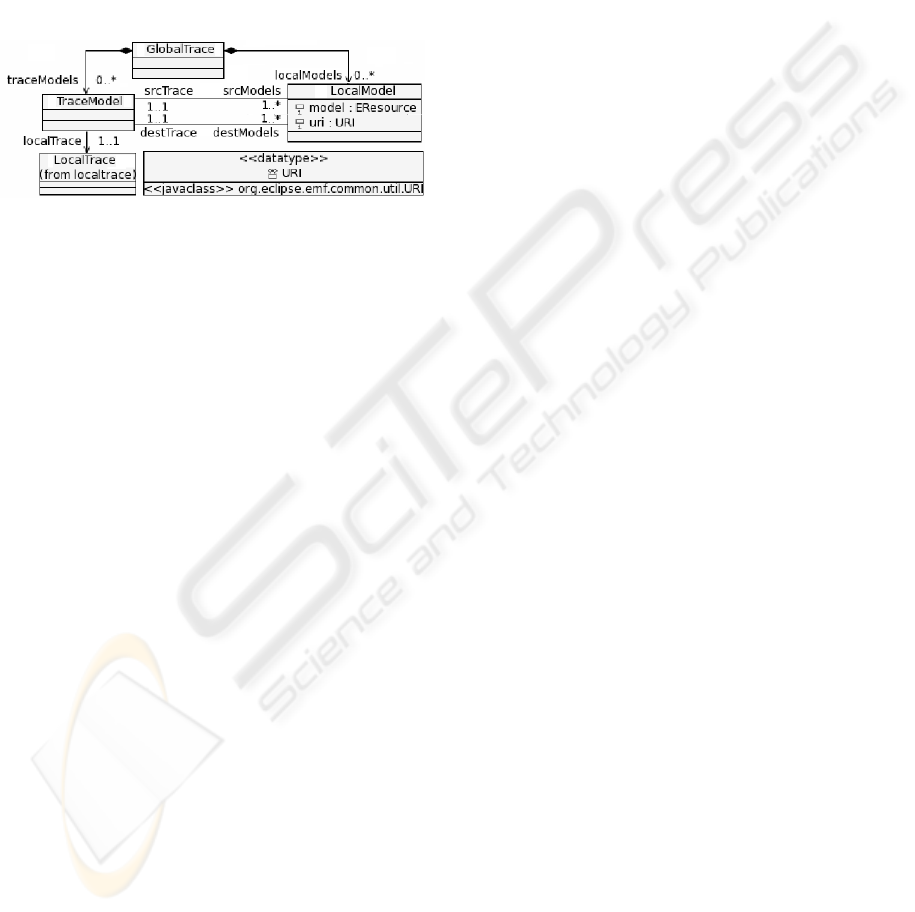
Figure 3 shows the global trace metamodel. Each
TraceModel produced during a transformation and re-
ferring to a LocalTrace, binds two sets of LocalMod-
els. These are shared out transformations, indicating
that they are produced by one transformation and con-
sumed by another. The GlobalTrace concept repre-
sents the root of the model.
Figure 3: Global Trace Metamodel.
4.3 Trace Generation
The proposed metamodels are completely language
independent. However trace generation requires in-
formation contained in the transformation and so re-
lies on the transformation language. Whatever the
transformation language, the trace generation is a two
steps algorithm. The first step corresponds to the pro-
duction of a local trace for each transformation and
the second, to the generation of the global trace spec-
ifying the transformation chain.
In the following, we only focus on the trace gener-
ation from transformation written in QVTO (Borland,
2007), an implementation of the standard QVT lan-
guage (Object Management Group, Inc., 2007).
The local trace generation has to be, if possible,
non-intrusive in the transformation code or in the en-
gine. The execution of the QVTO transformations
uses a trace mechanism to store a mapping between
model elements and to resolve reference. This trace
is relatively complex and dedicated to the transforma-
tion execution. However, it gathers the information
useful to generate the local trace models conformed
to our local trace metamodel. In particular, it refers
the source elements, their associated target elements
and the rule used to produce the latter from the for-
mer. The produced QVTO trace is transformed into a
local trace.
The global trace production is based on informa-
tion relative to the generated local traces. From the
local traces, the transformation sequence can be re-
built. Indeed, the models never appearing as output
models in any local traces are the start models. From
these models and traces, the other can be deduced.
If the transformation languages evolve, only the
local trace generation may be impacted. Indeed, this
latter directly relies on the used transformation lan-
guage, whereas the global trace is build from the local
traces.
4.4 Error Localization Algorithm
Our error localization algorithm requires that an er-
ror has been beforehand observed in an output model.
The transformation producing this model contains er-
rors. Our algorithm aims to reduce the investigation
field by highlighting the rule sequences which lead to
the observed error.
Our algorithm is based on the following hypoth-
esis. Let us consider two elements A and B of the
output model created by the rules toA() and toB() re-
spectively. If A references B through an association,
it assumes that the rule toA() calls the rule toB() or
makes an operation to reference B.
In case of an erroneous property (e.g. with an un-
expected value) in an element, the faulty rule is easily
identified. It corresponds to the RuleRef coupled to
the Link associated to the ElementRef referring the
selected element. In case of an error on an element
(e.g. added or missing), the faulty rule is one which
calls the last rule involved in the creation of the se-
lected element. Causes can be a missing or misplace
rule call.
We detail the algorithm in the second case:
1. select the faulty element and identify the model to
which it belongs
2. from the Global Trace model, recover the Lo-
cal Trace model whose the previously identified
model is one of the output models
3. look for the ElementRef corresponding to the se-
lected element in the local trace destContainer
4. recover the RuleRef associated to the Elemen-
tRefby navigating through the trace links,
5. store the RuleRef and the eObject type
6. search, in the destContainer, the ElementRef
which have their eObject linked by an association
to the eObject corresponding to the ElementRef
identified in step 3
7. apply recursively the algorithm from step 3 on
each element found in step 4
The recursive call stops when no direct linked
eObject can be found in step 6. The rule is called
by no other one; it is an entry point of the transforma-
tion. Technically, it is materialized by the storage of a
null pointer.
ICSOFT 2009 - 4th International Conference on Software and Data Technologies
70
Thus, the algorithm results in a kind of tree rep-
resenting the successions of rules producing the se-
lected element. It has been applied with success on
transformations written with different transformation
languages (QVTO and a Java API).
5 CASE STUDY
Debugging transformations, evenif they are simple, is
often a tough job. As soon as we operate a scale-up,
this task becomes unmanageable. In this section, we
illustrate how our approach eases transformation de-
bugging in the Gaspard2 environment by automating
the error localization.
5.1 Overview
Gaspard (DaRT Team, 2009) is a co-design envi-
ronment for Embedded Systems. In this environ-
ment, the hardware architecture and the application
are separately designed at a high level of abstraction
using UML enriched with the MARTE profile (Ob-
ject Management Group, 2007) dedicated to mod-
eling and analysis of real time and embedded sys-
tem. In order to generate code that will be used
for hardware-software co-simulation, functional ver-
ification or circuitry synthesis, several intermediate
metamodels representing different levels of abstrac-
tion have been specified. Each metamodel introduces
new concepts more platform-dependent. Transforma-
tions between these metamodels have been written
in order to automatically produce intermediate mod-
els and generate code. Thus several transformations
chains have been defined; one per targeted platform.
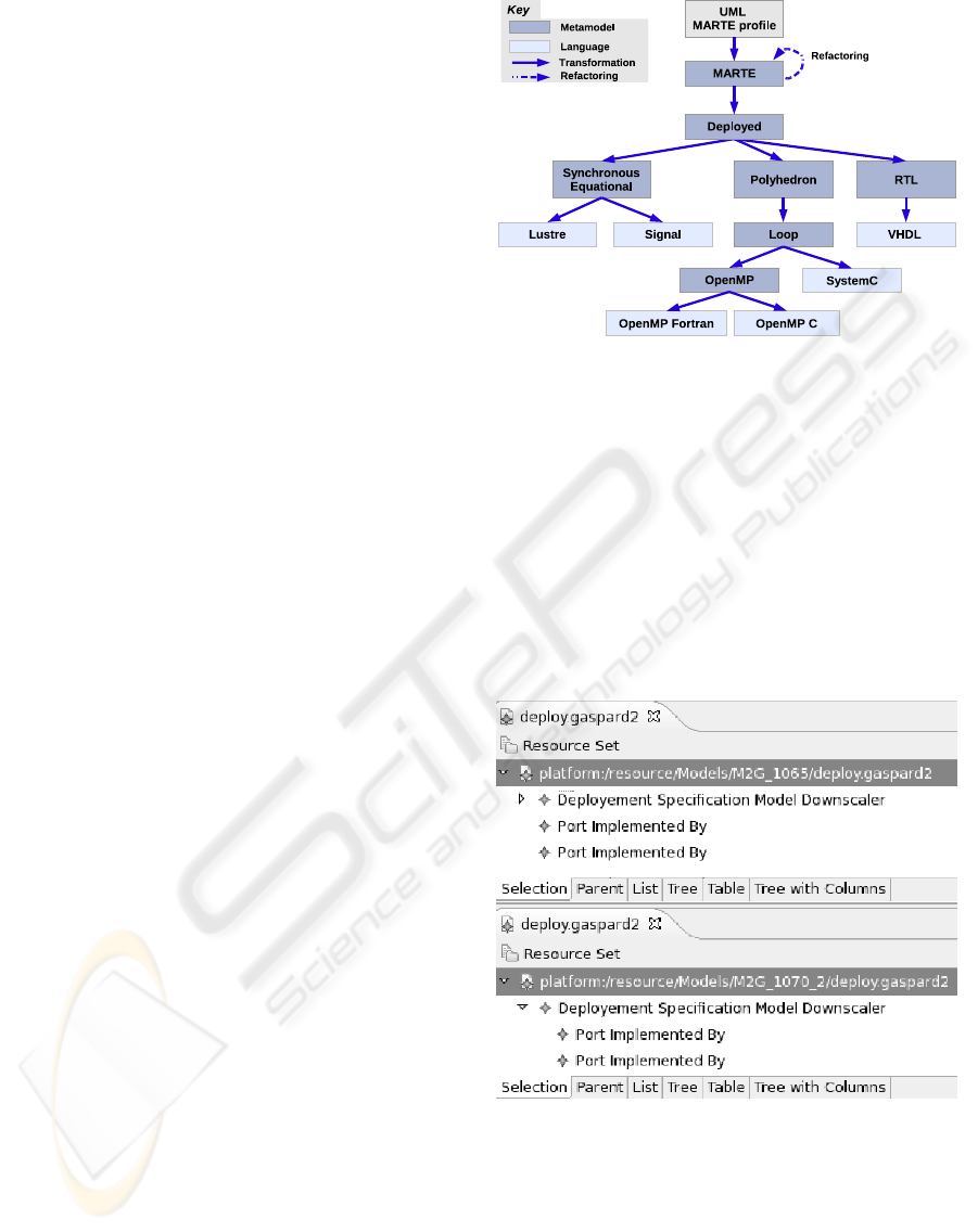
Figure 4 shows an overview of the MDE skeleton of
the Gaspard environment by specifying the metamod-
els and languages in presence and the transformations
between them (Gamati´e et al., 2008).
In this case study, we only focus on a single
transformation from the MARTE metamodel to the
Deployed metamodel. This transformation is writ-
ten with QVTO. The MARTE metamodel contains
around 80 metaclasses whereas the output metamodel
is in fact decomposed into five metamodels and con-
tains around 60 metaclasses.
The main idea is to test this transformation on an
input test model and, for example using an oracle
in order to observe an error on the produced model.
The oracle checks, among others, that any model pro-
duced by the transformation from the MARTE to the
Deployed metamodel has a unique root. This root
is a DeploymentSpecificationModel instance has been
Figure 4: MDE skeleton of Gaspard.
produced from an instance of the MARTE Model
metaclass.
5.2 Illustration of the Localization
Algorithm
Using our localization algorithm and from the error
reported by the oracle, we can debug more precisely
the transformation. First, the models correspondingto
the local and the global traces, have to be generated.
Figure 5: Excerpt of The generated output model(top) and
of the manually produced model (bottom).
The top of Figure 5 shows a fragment of the out-
put model. It contains several roots whose some (the
PortImlpementedBy) are not instance of the Down-
scaler:DeploymentSpecificationModel. An error on
an element is thus detected in the transformation. We
apply our error localization algorithm on one of the
output model “misplaced” elements in order to high-
TRACEABILITY MECHANISM FOR ERROR LOCALIZATION IN MODEL TRANSFORMATION
71
light the rule sequence and identify the faulty rule.
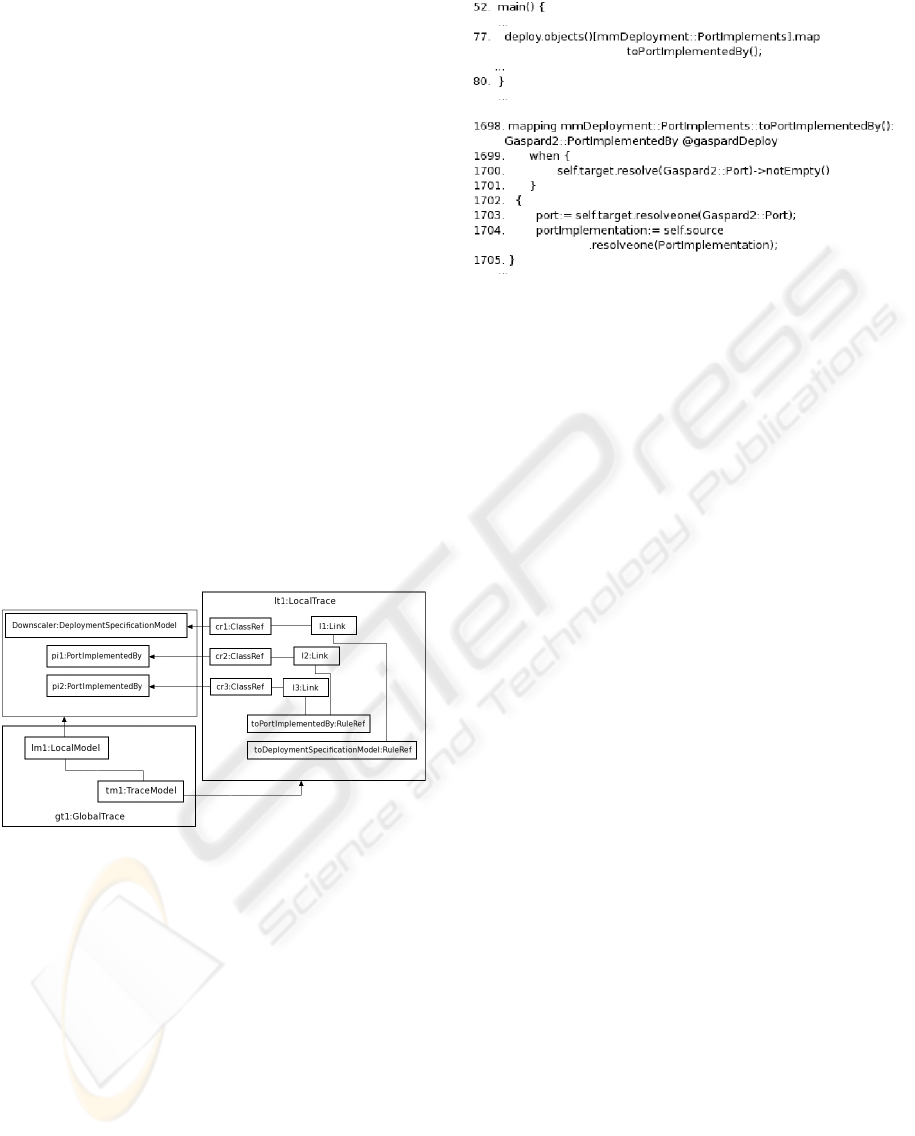
Figure 6 shows a sketch of the output model and
its associated traces. The algorithm begins with the
selection of a PortImplementedBy element. For ex-
ample, we select the pi1:PortImplementedBy element
that belongs to the deploy.gaspard2 model. The local
trace associated to this model is recovered using the
global trace model.
In the lt1:LocalTrace, cr2:ClassRef:ElementRef
corresponds to the pi1:PortImplementedBy. Navigat-
ing through the l2:Link associated to cr2:ClassRef,
the toImplementedBy:RuleRef rule is identified and
stored. Then, ElementRefs are scanned to identify
elements linked to pi1:PortImplementedBy. Here,
neither the deploy.gaspard2 model nor other models
produced by the transformation own elements linked
through an association (including compositions) to
the pi1:PortImplementedBy. So, this step returns
nothing, the toImplementedBy:RuleRef rule is not
called by another rule. Thus a null pointer is stored
and the algorithm stops executing. The produced rule
calls tree contains only two elements: the RuleRef
named toPortImplementedBy associated to the type of
the eObject on which it is applied; (PortImplements)
and the null pointer.
Figure 6: Excerpt of the output model, of the local and the
global trace models.
In Figure 7 we present a piece of the QVTO trans-
formation code illustrating that the rule is called by
the main function (line 77). The code of the rule itself
corresponds to line 1698 to 1705.
The precedent analysis leads to the conclusion that
the toPortImplementBy rule may be called by another
rule or a reference is missing in a rule. Further anal-
ysis can be done by manually specifying an expected
output model (top of Figure 5) corresponding to the
input model. Comparing the generated output model
to this new one, we can see that the Deployment-
Model contains PortImplementedBy elements. So the
rule call should be moved from the main entry point to
the rule which creates the DeploymentModel element.
The example developed here is quite simple, but
Figure 7: QVTO Transformation Excerpt.
illustrates the easiness to identify a faulty rule in a
huge transformation (more than 2000 lines of code).
This algorithm has to be used in the context of a trans-
formation test. It requires the results of the test gener-
ation and the errors observation steps. It reduces the
field of potential faulty rule to the only rules involved
in an element creation. Thus, using this approach, we
havereduced the search field for the previous example
to one rule.
5.3 Error Localization in
Transformation Chain
The algorithm presented in section 4.4 is dedicated to
error localization in a single transformation, but we
develop a variation adapted to transformation chain.
Not only the successive rules are stored but also any
element of the input model that was useful to the cre-
ation of the faulty output element. The algorithm is
then again applied on each of these elements. The
final result is a set of rules corresponding to the set
of potential faulty rules on the whole transformation.
For sake of space we do not illustrate this algorithm
which has nevertheless be successfully implemented
and used with the Gaspard transformation chain.
6 CONCLUSIONS AND FUTURE
WORKS
In this paper, we have proposed a traceability based
mechanism to locate errors in a single model trans-
formation or a transformation chain. It reduces the
investigation field to the rules called to create an out-
put element identified as erroneous in a preliminary
test phase. The localization is based on three main
parts, an error observed in an output model, our trace
models and the localization algorithm. The error can
ICSOFT 2009 - 4th International Conference on Software and Data Technologies
72

be point out by an oracle whereas the traces give the
support for the localization algorithm.
As the algorithm is based on our traces meta-
models, it is purely language independent and can be
reused for any transformationlanguages as long as the
local and the global trace are generated. For the exper-
imentation, we use our approach on transformation
written in QVTO. It has also been successfully tested
on transformations using a dedicated Java API. Our
approach has shown its efficiency on the transforma-
tion chains of the Gaspard framework. A qualitative
and quantitative study is in progress.
Currently, the localization gives a set of potential
faulty rules. To exactly determine the faulty rule, the
set returned by the algorithm must be manually an-
alyzed. This final step can be automatized by intro-
ducing new oracle answers. Indeed, with some addi-
tional information, we could, little by little, reduce the
search field to a faulty rule and find the rule to modify.
In this paper, we only deal with model to model
transformation. We are currently working on the man-
agement of traceability in model to text transforma-
tion. The local trace metamodel has to be enhanced
with the specificities of code generation. The adap-
tation of the error algorithm may be more complex
since model to text transformations are rarely decom-
posed into rules.
REFERENCES
Amar, B., Leblanc, H., and Coulette, B. (2008). A Trace-
ability Engine Dedicated to Model Transformation for
Software Engineering. In ECMDA Traceability Work-
shop, Berlin, pages 7–16.
Barbero, M., Didonet, M., Fabro, D., and B´ezivin, J. (2007).
Traceability and provenance issues in global model
management. In ECMDA Traceability Workshop.
Borland (2007). Qvt - o. http://www.eclipse.org/m2m/qvto/
doc.
Czarnecki, K. and Helsen, S. (2006). Feature-based sur-
vey of model transformation approaches. IBM Sys-
tems Journal, 45(3):621–646.
DaRT Team (2009). Graphical Array Specification for
Parallel and Distributed Computing (GASPARD2).
http://www.gaspard2.org/.
Falleri, J. R., Huchard, M., and Nebut, C. (2006). Towards
a traceability framework for model transformations in
kermeta. HAL - CCSd - CNRS.
Fleurey, F., Baudry, B., Muller, P.-A., and Le Traon, Y.
(2007). Towards dependable model transformations:
Qualifying input test data. SoSyM.
Galvao, I. and Goknil, A. (2007). Survey of traceability ap-
proaches in model driven engineering. In the Eleventh
International IEEE EDOC Conference (EDOC 2007),
pages 313–324. IEEE Computer Society Press.
Gamati´e, A., Le Beux, S., Piel, E., Etien, A., Ben Atitallah,
R., Marquet, P., and Dekeyser, J. (2008). A Model
Driven Design Framework for High Performance Em-
bedded Systems. Technical Report 6614, INRIA.
Glitia, F., Etien, A., and Dumoulin, C. (2008). Traceability
for an MDE Approach of Embedded System Concep-
tion. In ECMDA Tracibility Workshop, Germany.
IEEE (1991). IEEE standard computer dictionary : a com-
pilation of IEEE standard computer glossaries. IEEE
Computer Society Press, New York, NY, USA.
Jouault, F. (2005). Loosely coupled traceability for atl. In
ECMDA Workshop on Traceability.
Kolovos, D. S., Paige, R. F., and Polack, F. A. (2006). On-
demand merging of traceability links with models. In
ECMDA Workshop on Traceability, Bilbao, Spain.
Mottu, J.-M., Baudry, B., and Le Traon, Y. (2008). Model
transformation testing : oracle issue. In MoDeVVa
workshop colocated with ICST’08., Norway.
Object Management Group (2007). A UML profile for
MARTE. http://www.omgmarte.org.
Object Management Group, Inc. (2007).
MOF Query / Views / Transformations.
http://www.omg.org/docs/ptc/07-07-07.pdf. OMG
paper.
Reshef, A. N., Nolan, B. T., Rubin, J., and Gafni, S. Y.
(2006). Model traceability. In IBM SYSTEMS JOUR-
NAL, volume 45.
Vanhooff, B., Ayed, D., Baelen, S. V., Joosen, W., and
Berbers, Y. (2007). Uniti: A unified transformation
infrastructure. In MoDELS, pages 31–45.
Velegrakis, Y., Miller, R. J., and Mylopoulos, J. (2005).
Representing and querying data transformations. In
ICDE : Proceedings of the International Confer-
ence on Data Engineering, pages 81–92, Washington,
USA. IEEE Computer Society.
TRACEABILITY MECHANISM FOR ERROR LOCALIZATION IN MODEL TRANSFORMATION
73
