DECISION SUPPORT SYSTEM FOR A COMMANDER
AT THE OPERATIONAL LEVEL
Jan Hodicky and Petr Frantis
Communication and Information Departement, University of Defence, Kounicova 44, Brno, Czech Republic
Keywords: Common Operational Picture, Virtual Reality, Command and Control, Decision Making Process.
Abstract: A current trend in command and control visualization systems is to show a real situation in relation with 3D
terrain data and real information about objects, tactical symbols, waters, woods and roads as well.
Implementing the Network Enabled Capability (NEC) concept is the main transformation process in the
Czech Army. The one of the main NEC outputs is a common operational picture. This article deals with a
design and an implementation of services for common operational picture data visualization supported by
Service Oriented Architecture. The article is built on a current status of a NEC implementation process. The
main output of this project is a prototype of visualization system that can be used by a commander and its
staff at the brigade level. The operator can easily see the real situation at the theatre supported by LINK 16
standard and a connection with Czech ground C2 system and virtual reality devices. This system is designed
to support decision making process of a commander.
1 INTRODUCTION
The industrial age began in 18
th
century. Energy and
engines were widely used in this age. The
information age was its successor. In this age, in
20
th
century, a value is gained by information
sharing and communication nets using. The
information age also affected the warfare. The main
factors of information age in the warfare are:
Data and information;
Communication environment;
Security;
Interoperability;
Warfare digitalization.
The warfare digitalization can be characterized
by using an information technology in the processes
of data acquisition, data storage, data transformation,
data change and data and information evaluation in
the area of interest of the warfare. The main aim of
the warfare digitalization is to create a shared
common operational picture of the warfare. The
common operational picture is the main instrument
of the Networked Centric Warfare (NCW) concept
in the US army and the Network Enabled Capability
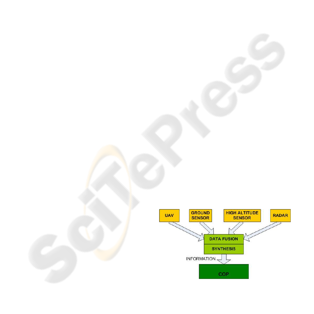
(NEC) concept in NATO nations. The common
operational picture shows the commander the
current situation in the battlefield in real time. He
can easily see the position of friendly and enemy
units. This must be supported by a communication
and information infrastructure (CII). The CII
includes sensors in high altitudes, unmanned aerial
vehicles (UAV), alert radars, ground sensors, etc.
The CII harvests data and transforms them into
information that is used in the common operational
picture. The common operational picture is usually
displayed on the visualizations devices, such as
monitor, LCD or projection system. The common
operational picture brings better situational
awareness.
Figure 1: Common operational picture – architecture
approach.
359
Hodicky J. and Frantis P. (2009).
DECISION SUPPORT SYSTEM FOR A COMMANDER AT THE OPERATIONAL LEVEL .
In Proceedings of the International Conference on Knowledge Engineering and Ontology Development, pages 359-362
Copyright
c
SciTePress
2 VIRTUAL REALITY PROJECT
IN CZECH C2 SYSTEM
In 2007, The Defense department of the Czech
Republic accepted a new research project called:”
Virtual reality devices in ground forces tactical
command and control system (GFTCCS)”. The
project concentrates on increasing commander
situational awareness at a tactical and operational
level in three dimensional (3D) terrain visualization.
This project is based on integration of virtual reality
devices into command and control process.
The main project goal was a demonstration of a
new presentation layer of GFTCCS with virtual
reality devices. A global architecture of GFTCCS
was designed in 1999 and its presentation abilities
were obsolete. The commander could get
information about battlefield in 2 dimensions (2D)
only. The terrain spatial data were available but they
were not used to visualize the battlefield in 3D.
Communication between the commander and
GFTCCS was supported only by a mouse or
keyboard. A resolution of visualized battlefield was
given by output devices abilities - CRT or LCD
monitors. The old presentation layer offers common
features of Geographic Information Systems (GIS)
such as zoom in, zoom out or movement of actual
position over a map.
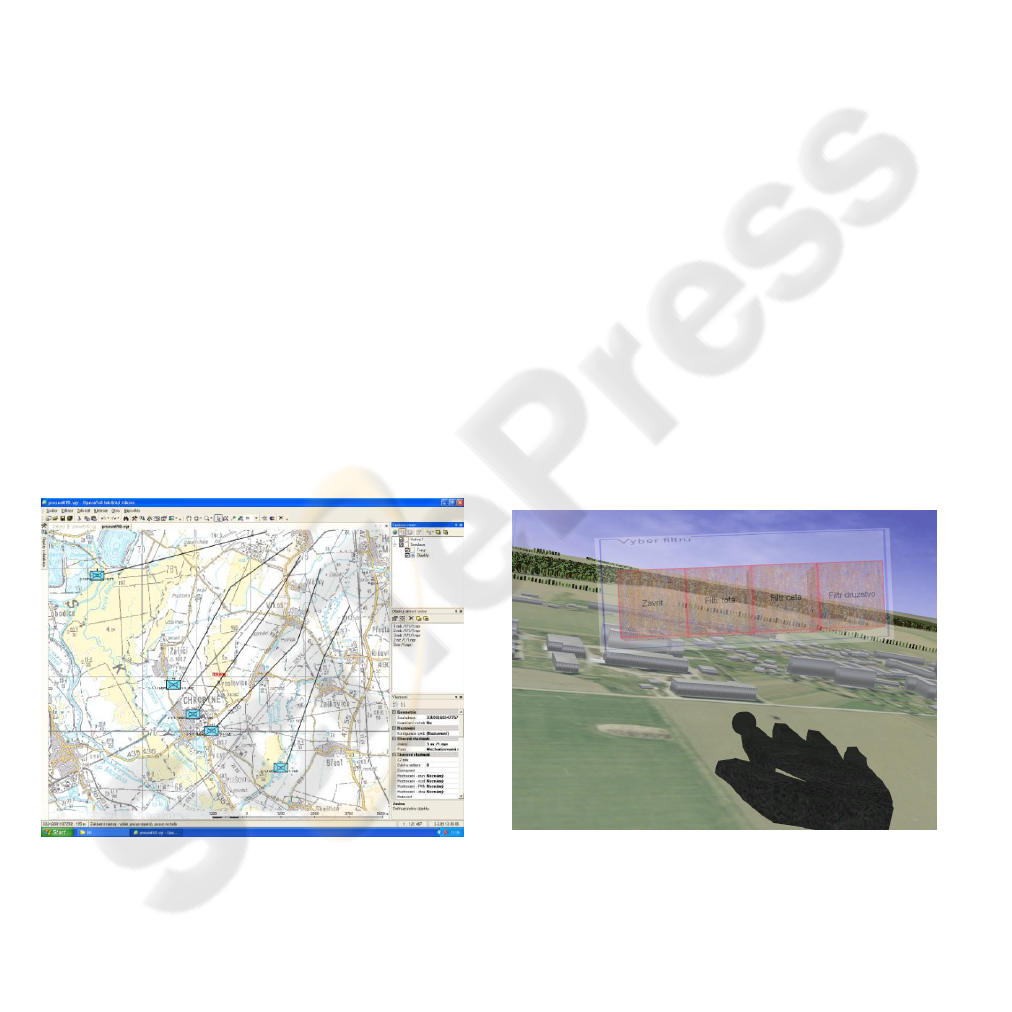
The main ability of GFTCCS is to show a
position of friendly forces as it can be seen on the
picture bellow.
Figure 2: Old presentation layer of GFTCCS.
The new presentation layer comes out from
experience with virtual reality devices in the
modeling and simulation world. The virtual reality
devices are heavily used in this field. Head mounted
displays (HMD), data gloves and tracking systems
are implemented in the training process of
individuals and units at the tactical level.
Knowledge of virtual reality devices opened a
new way to command and control in military
domain. The main idea is to increase the level and
quality of information about battlefield. This can be
rapidly increased by virtual reality devices. The
actual battlefield situation is projected into HMD in
very high resolution. The commander can operate
the virtual reality environment by head movements.
The left head rotation moves the current scene into
the left area of interest. The right head rotation
works on the contrary. The movement of the whole
body of commander creates effect of flying over the
virtual terrain. The commander can also use a data
glove to communicate with a new presentation layer.
Predefined gestures can manipulate the virtual
reality battlefield. In this way, the commander can
get the more detailed information about the area of
interest, or detailed information about selected unit.
The HMD and data glove is tracked by tracking
sensors to get the information about head and hand
position. The important fact is that the current
situation of the battlefield is projected in 3D. This
feature is supported by terrain database generator. It
offers 3D model of the area of interest created from
digital map resources. This data can be shared by
GTFCCT or duplicated in special data storage.
The picture bellow shows the current view on the
battlefield in 3D. This scene is projected into HMD
and the commander can use virtual hand to work in
virtual reality environment.
Figure 3: New presentation layer of GFTCCS.
The new presentation layer with virtual reality
devices is designed to be used at the brigade level.
KEOD 2009 - International Conference on Knowledge Engineering and Ontology Development
360
3 NEW PRESENTATION LAYER
ARCHITECTURE
Essential applications of GFTCCS that must be used
in a new presentation layer with virtual reality
devices (PLVR) are tactical situation (TS),
identification of friendly position (FP), identification
of enemy position (EP), electronic overlays (EO).
These applications create inputs from GFTCCS into
PLVR and are used to visualize quantitative and
qualitative information about friendly and enemy
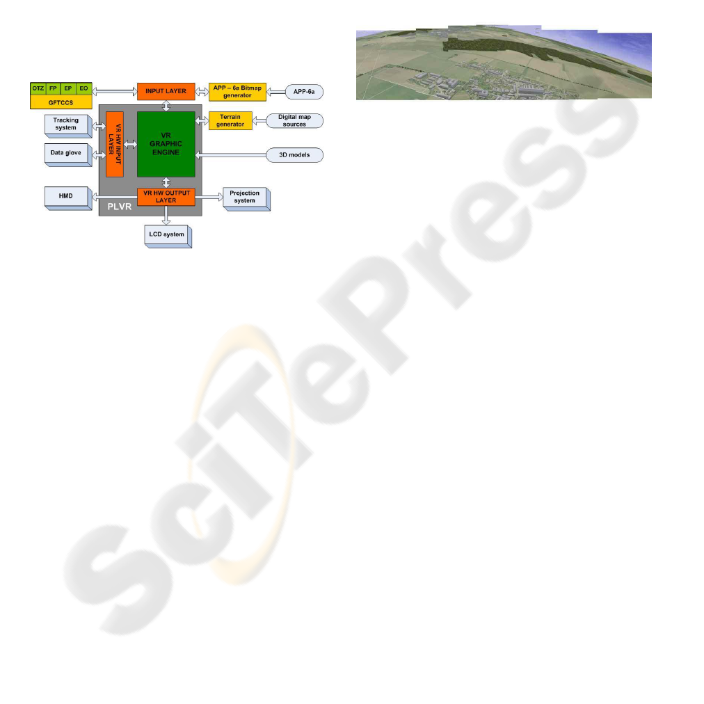
forces and other battlefield objects. The picture
bellow shows the global architecture of design of a
new presentation layer GFTCCS.
Figure 4: PLVR architecture.
Input layer is designed as a web service. It can be
implemented as Service Oriented Architecture
(SOA) for interoperability achievement in the case
of interconnection with another C2 system. This
layer provides services such as current position of
friendly units. This layer offers connection into MS
SQL Server in an implementation scope. MS SQL
Server contains data about position of units and its
code for visualization of tactical symbol in APP –
6a. MS SQL Server contains complementary data
about units and its hierarchy. This information can
be used in an aggregation function. Input layer also
provides bitmap representation of APP – 6a tactical
symbol.
Terrain database generator offers 3D model of
the area of interest that is prepared from map
sources. This digital data are shared in GFTCCS or
can be located in data storage. The generation is
power consuming operation thus runs separately on
a local computer based on 64-bit platform. The
connectivity with graphics engine is solved by SOA
implementation. VR HW input layer supports
interconnection between the data glove and a
graphics engine and also interprets its positions into
VR environment coordinate system. It is
implemented as API with local function call. This
layer also implements gesture recognition and
translation that can be used by the commander to
operate the VR environment.
VR graphic engine visualizes the area of interest
in 3D with data from input devices, input layer and
preprocessed 3D model of trees, roads, buildings,
etc. The final scene is sent into VR HW output layer
that must correct it to visualize in HMD, LCD
systems, projection system or combination of
already mentioned devices.
Figure 5: Panoramatic visualization.
4 DATA REPRESENTATION
The current state of the art in data representation is
set by the US Force XXI Battle Command Brigade
and Below (FBCB2) system and its new presentation
layer component Command and Control in 3
dimensions that renders the battlefield information
into a 3 dimensions environment in real time (“CG2
C3D”, 2007). But this solution uses neither VR
devices nor tactical symbol representation in 3D.
Data representation is based on ontology that was
designed to interpret knowledge of NEC concept for
human being (Hodicky, 2009). Topic maps method
was chosen to describe information of NEC domain.
Tactical symbols are visualized as a block or a
spatial object that is semi transparent. They have
also the APP – 6a bitmaps on the surfaces and other
important information about current status of unit.
Additional information (combat efficiency, velocity,
fuel, etc.) are visualized as bar graphs.
5 POSSIBLE ENHANCEMENTS
A new presentation layer with VR devices creates a
supplementary tool to get common operation picture
of ground forces. The main tool that support
command and control process remains the old
presentation layer. A new one enhances the
GFTCCS ability to show the common operational
picture in 3D. Information from air forces domain
can be also sent into this presentation layer. The
current communication between aircrafts and ground
DECISION SUPPORT SYSTEM FOR A COMMANDER AT THE OPERATIONAL LEVEL
361
support system is based on tactical data link called
LINK 16. The new presentation layer is designed as
open architecture. We can easily modify input layer,
especially web services that will interpret LINK 16
code into graphics engine. It can support joint
operation between ground and air forces. In the joint
operation center the commander can see the position
of aircrafts, helicopters and ground forces as well.
This presentation layer is designed to support
staff at the brigade level. GFTCCS is currently able
get information about units’ positions. It is not
possible to get information about vehicles and
individual soldiers. This should be changed this
year. After this improvement, the presentation layer
can be easily transformed to visualize battlefield
with models of individual vehicles and even
soldiers. This can support battlefield operation for
intelligence units or tactical units at the company or
battalion level.
The VR HW output layer can be also modified to
be able to connect to projection system that will be
used by commander staff in the same time as the
commander.
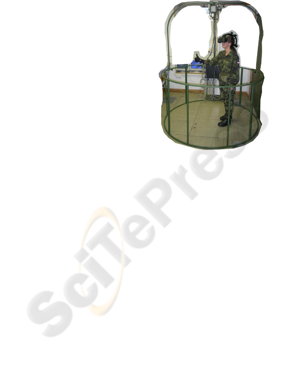
6 CONCLUSIONS
The new presentation layer with virtual reality
devices is a support tool that shows the common
operational picture to the commander at the brigade
level. It visualizes the area of interest in real time
into HMD in relation with 3D terrain data and units’
positions. It supports the decision making process of
a commander. The picture bellow shows the
prototype of HW realization of the new presentation
layer. This system with only a few modifications has
been deployed in the field exercise Network
Challenge on May 2009 at the brigade level and was
favorably accepted. The level of battlefield
knowledge was increased by 3D terrain
implementation and a new style of data
representation.
REFERENCES
CG2 C3D Demonstration Application Employed in U.S.
Army AAEF Exercise Tests Real-Time 3D
Visualization of on the - Move C4ISR Data from
FBCB2 VMF Messages. (2008). Retrieved March 25,
2008 from http://www.cg2.com/Press.html
Hodicky, J., Frantis, P., 2009. Knowledge system in C2
and NEC concept. In DLSC 2009. University of
Defence.
Figure 6: Prototype of HW realization.
KEOD 2009 - International Conference on Knowledge Engineering and Ontology Development
362
