
Modeling and Model-based Control of Homogeneous
Charge Compression Ignition (HCCI) Engine Dynamics
Rolf Johansson
1
, Anders Widd
1
and Per Tunest˚al
2
1
Department of Automatic Control, Lund University, PO Box 118, SE22100 Lund, Sweden
2
Department of Energy Sciences, Div. Combustion Engines, Lund University
PO Box 118, SE22100 Lund, Sweden
Abstract. The Homogeneous Charge Compression Ignition (HCCI) principle
holds promise to increase efficiency and to reduce emissions from internal com-
bustion engines. As HCCI combustion lacks direct ignition timing control and
auto-ignition depends on the operating condition, control of auto-ignition is nec-
essary. Since auto-ignition of a homogeneous mixture is very sensitive to op-
erating conditions, a fast combustion phasing control is necessary for reliable
operation. To this purpose, HCCI modeling and model-based control with ex-
perimental validation were studied. A six-cylinder heavy-duty HCCI engine was
controlled on a cycle-to-cycle basis in real time using a variety of sensors, actu-
ators and control structures for control of the HCCI combustion in comparison.
The controllers were based on linearizations of a previously presented physical,
nonlinear, model of HCCI including cylinder wall temperature dynamics. The
control signals were the inlet air temperature and the inlet valve closing. A sys-
tem for fast thermal management was installed and controlled using mid-ranging
control. The resulting control performance was experimentally evaluated in terms
of response time and steady-state output variance. For a given operating point, a
comparable decrease in steady-state output variance was obtained either by in-
troducing a disturbance model or by changing linearization point. The robustness
towards disturbances was investigated as well as the effects of varying the pre-
diction and control horizons. Increasing the horizons had a very limited effect on
the closed-loop performance while increasing the computational demands sub-
stantially. As shown in the paper, modeling constitutes a necessary element for
embedded networked control design applied to HCCI combustion engine design.
1 Introduction
The motivation for studying the homogeneous charge compression ignition (HCCI) en-
gine principle is the promise of low levels of exhaust emissions with regards to NO
x
,
while still retaining an acceptable overall efficiency [15]. Pioneering efforts towards
this new engine principle—also called controlled auto-ignition (CAI)—were reported
in [42,57, 21,14,30]. Depending on the purpose, modeling of HCCI engine dynamics
may exhibit different complexity and format such as:
– Multi-zone models including chemical kinetics to simulate engine operation in a
large operating range;
Johansson R., Widd A. and Tunest
˚
al P. (2009).
Modeling and Model-based Control of Homogeneous Charge Compression Ignition (HCCI) Engine Dynamics.
In Proceedings of the International Workshop on Networked embedded and control system technologies: European and Russian R&D cooperation,
pages 31-44
Copyright
c
SciTePress

– Multidimensional CFD for optimization of fuel injection and combustion chamber
design;
– Single-zone reduced-order dynamic models (for model-based control).
A significant challenge with HCCI is the control of the combustion phasing, this is
essential in order to control the load, to obtain low fuel consumption and emissions. For
closed-loop control of the combustion phasing, feedback signals are necessary and in-
cylinder pressure feedback is, perhaps, the most straightforward approach. In practice,
the crank angle α of 50% burnt fuel (CA50 or α
50
or θ
50
) has proved to be a reliable
indicator of on-going combustion [41,6]. In closed-loop control of an HCCI engine,
several means to actuate the combustion phasing have been tested—e.g., dual fuels [41,
6,8], variable valve actuation (VVA) [1,8], variable compression ratio [15,27], and
thermal management [38, 28].
For control design purposes and embedded control design exploiting information
from networked sensors, appropriate models and system variables useful for feedback
control are needed. Previously, it was shown that physical modeling and system iden-
tification can be used to obtain low-complexity models of the HCCI dynamics [58,7,
51]. For closed-loop HCCI engine operation, it was reported that the combustion phas-
ing can be stabilized by means of a PID controller [41]; LQG control [58]; and MPC
control [8].
A fast and robust control of α
50
appears to be necessary in order to stabilize HCCI
engine control. It is also desirable that the load, peak cylinder pressure, peak rate of
cylinder pressure and emissions are controlled simultaneously. This is a multi-input
multi-output (MIMO) control problem where the controller has to be able to handle
constraints on several variables. In a comparison among several control methods, it
will be demonstrated that Model Predictive Control (MPC) control could be used with
favorable properties [4,35]. All of the actuators suggested have control constraints and
MPC has the benefit of explicitly taking the constraints into account.
Whereas monitoring of α
50
or other methods to sense on-going combustion for
feedback control of an HCCI engine all rely on pressure sensors, these sensors may be
expensive. One candidate to replace pressure sensors is the use of electronic conductive
properties for the reaction zone [24]. This phenomenon is called ion current for which
no expensive sensor is needed. Ion current has been successfully used in closed-loop
control of SI engines [20]. The basic principle of ion current sensing is that a voltage
is applied over an electrode gap inserted into the gas volume (combustion chamber)
[24]. The common belief so far has been that ion current levels are not measurable for
the highly diluted HCCI combustion. However, a recent study shows that it is not the
dilution level in itself but the actual fuel/air equivalence ratio φ which is an important
factor for the signal level [22,58].
In this paper, we will report new modeling and experimental results on HCCI con-
trol, complementingour previously published results on control of a six-cylinderheavy-
duty engine, evaluating a variety of control methods (MPC and PID) and actuators
(VVA, dual fuel), and experimental results on HCCI control of a single-cylinder heavy-
duty engine evaluating a variety of sensors (in-cylinder pressure, ion current) [8,9, 7].
The purpose of this paper is to provide a survey of state-of-the-art HCCI engine
modeling with particular attention to control-oriented modeling relevant for networked

embedded system design. The structure of the paper is the following: An overview of
HCCI modeling is given with particular emphasis on modelingsuitable for model-based
control, followed by a model-based control description, discussion and conclusions.
2 HCCI Modeling
There are two often used methods to obtain models of HCCI engine dynamics suitable
for control; physical modeling [51] and modeling by means of system identification
[7–9]. Physical modeling based on conservation laws and chemical kinetics has attrac-
tive intuitive component-based features but suffers from complexity issues with adverse
effects in application. Whereas system identification has proved to be a very effective
modeling tool for prototyping, it may provide results hard to interpret from a physical
point of of view.
The purpose of modeling has an obvious influence on focus and the complexity of
modeling [33,19]. As modeling and simulation may easily become too detailed and
computationally expensive to serve purposes of model-based control, low-complexity
models and reduced-order models become relevant. A minimum requirement of phys-
ical modeling is explanation of the nature of the in-cylinder pressure traces where
adiabatic compression combines with fuel-dependent auto-ignition [43], [10], [23]. In
previous work, modeling choices involve aspects of chemical kinetics, cycle-to-cycle
coupling, in-cylinder concentrations of reactants, wall temperature dynamics, pressure
dynamics, and auto-ignition timing.
Modeling details fall into categories of single-zone models, multi-zone models,
multidimensional computational fluid dynamics (CFD) models, sometimes combined
with exosystem simulation on the form of stochastic disturbances, load modeling, sen-
sor modeling. Both physical aspects and operational aspects require attention. Shaver
et al. singled out six distinct stages in modeling of HCCI engine operation—i.e., induc-
tion, compression, combustion, expansion, exhaust and residence in the exhaust man-
ifold [52,53,45]. As for stable operation, combustion phasing control design requires
appropriate models and system output variables usable for feedback control. Recently,
mode-transition operation and control of Diesel-HCCI and SI-HCCI engines and other
hybrid control aspects have received attention [54].
2.1 Fuel Modeling
The necessity of developing a practical iso-octane mechanism for HCCI engines was
presented after various different experiments and currently available mechanisms for
iso-octane oxidation being reviewed and the performance of these mechanisms applied
to experiments relevant to HCCI engines being analyzed [48,39]. A skeletal mecha-
nism including 38 species and 69 reactions was developed, which could predict satis-
factorily ignition timing, burn rate and the emissions of HC, CO and NO
x
for HCCI
multi-dimensional modeling [39]. Comparisons with various experiment data including
shock tube, rapid compression machine, jet-stirred reactor and HCCI engine indicate
good performance of this mechanism over wide ranges of temperature, pressure and
equivalence ratio, especially at high pressure and lean equivalence ratio conditions. By

applying the skeletal mechanism to a single-zone model of an HCCI engine, it was
found that the results were substantially identical with those from the detailed mecha-
nism developed by Curran et al. [18] but the computing time was reduced greatly [39].
A model for the auto-ignition of hydrocarbons applicable to 3D internal combus-
tion engine calculations was proposed [16]. The limits of classical methods using an
auto-ignition delay are investigated when cool flame phenomena are present. A method
based on tabulated reaction rates was presented to capture the early heat release in-
duced by low temperature combustion. Cool flame ignition delay when present and
cool flame fuel consumption are also tabulated. The reaction rate, fuel consumption,
and cool flame ignition delay tables were built a priori from complex chemistry calcu-
lations. The reaction rates, which directly depend on instantaneous changes of thermo-
dynamic conditions, were then integrated during the 3D engine calculation. The model
is first validated through comparisons with complex chemistry calculations in constant
and variable volume configurations where good agreement was found. The model was
applied both to a Diesel computation with spray injection and residual gases, and to
a Diesel-HCCI configuration. Comparisons with experimental results showed that the
auto-ignition essential features were well reproduced in these cases [16].
The combination of CFD computations with detailed chemistry leads to excessive
computation times, and is not achievable with current computer capabilities. A reduced
chemical model for n−heptane is described, in view of its implementation into a CFD
simulation code [37]. Firstly, the reduction process to get to the 61-step mechanism
is detailed and then the 26-step mechanism is described; this further reduction is car-
ried out under various conditions that include a range of interest in engine applications.
Validation work in reference to the original detailed mechanism and two reduced mech-
anisms was published in the literature, focusing on the prediction of ignition delay times
under constant as well as variable volume conditions [37]. A good and accurate repro-
duction of both ignition delay times and heat release was reported to be reached with
the 26-step model [37].
Despite the rapid combustion typically experienced in HCCI, components in fuel
mixtures do not ignite in unison or burn equally. In experiments and modeling of blends
of diethyl ether (DEE) and ethanol, the DEE led combustion and proceeded further to-
ward completion, as indicated by
14
C-isotope tracing [36]. A numerical model of HCCI
combustion of DEE and ethanol mixtures supports the isotopic findings. Although both
approaches lacked information on incompletely combusted intermediates plentiful in
HCCI emissions, the numerical model and
14
C-tracing data agreed within the limita-
tions of the single-zone model. Despite the fact that DEE is more reactive than ethanol
in HCCI engines, they were sufficiently similar and prevented incidence of a large elon-
gation of energy release or significant reduction in inlet temperature required for light-
off, both desired effects for the combustion event. This finding suggests that, in general,
HCCI combustion of fuel blends may have preferentialcombustion of some of the blend
components [36].
2.2 Auto-Ignition Modeling
Whereas HCCI engines have been shown to have higher thermal efficiencies and lower
NO
x
and soot emissions than spark ignition engines, the HCCI engines experience very

large heat release rates which can cause too rapid an increase in pressure. One method
of reducing the maximum heat-release rate is to introduce thermal inhomogeneities,
thereby spreading the heat release over several crank angle degrees [55]. Direct numer-
ical simulations (DNS) showed that both ignition frontsand deflagration-likefronts may
be present in systems with such inhomogeneities [17]. Here, an enthalpy-based flamelet
model was presented and applied to four cases of varying initial temperature variance.
This model used a mean scalar dissipation rate to model mixing between regions of
higher and lower enthalpies. The predicted heat-release rates agree well with the heat
release rates of the four DNS cases. The model was shown to be capable of capturing
the combustion characteristics for the case in which combustion occurs primarily in the
form of spontaneous ignition fronts, for the case dominated by deflagration-type burn-
ing, and for the mixed mode cases. The enthalpy-based flamelet model shows consid-
erably improved agreement with the DNS results over the popular multi-zone model,
particularly, where both deflagrative and spontaneous ignition are occurring, that is,
where diffusive transport is important [17]. Another fuel model is the Shell model used
for auto-ignition below [26]. Further contributions on auto-ignition modeling can be
found in [47].
2.3 Thermal Modeling and Auto-Ignition
HCCI combustion is often achieved without a completely homogeneous mixture. In
order to derive a control-relevant model, however, we might firstly proceed by assum-
ing that the mixture is homogeneous, thus allowing a single-zone cylinder model [5].
Such assumptions may be justified by laser-diagnostic measurements in our experi-
mental set-up [46]. To reproduce the effects relevant for combustion phasing control
it is required that the auto-ignition model captures the effects on ignition delay (induc-
tion time) of varying species concentrations, temperature trace, and fuel quality. Several
alternative approaches are possible for modeling the instant of auto-ignition for fuels.
High-complexity models—e.g., (Primary Reference Fuels (PRF), 857 species, 3,606
reactions, CHEMKIN/LLNL) [56]—have been used to model complete combustion. In
addition to ignition prediction, such models are also aimed at describing intermediate
species and end product composition. Reduced chemical kinetics models, e.g., (PRF
fuels, 32 species, 55 reactions, CHEMKIN) [60], have also been proposed, where re-
actions with little influence on the combustion have been identified and removed. For
simulation of multi-cycle scenarios it is necessary to keep the model complexity low in
order to arrive at reasonable simulation times. An attractive and widespread alternative
is to use the Shell model [26], which is a lumped chemical kinetics model using only
five representative species in eight generic reactions. This model is aimed at prediction
of auto-ignition rather than describing the complete combustion process. Compression
ignition delay may also be described by empirical correlations, such as the knock inte-
gral condition
Z
t
i
t=0
dt
τ
= 1 (1)
where t
i
is the instant of ignition and τ is the estimated ignition time (ignition delay)
at the instantaneous pressure and temperature conditions at time t, often described by

Arrhenius type expressions [29,49]. A drawback is that dependence on species concen-
trations is normally not regarded. An integral condition with concentration dependence
was used in [50,51] in a similar study for propane fuel, where also auto-ignition models
based on very simple reaction mechanisms were evaluated. Alternatives to physical or
physics-based models are to use system identification to obtain models or to use empir-
ical look-up tables. The latter gives insufficient physical insight, and require substantial
efforts to calibrate. In this work, the Shell model was chosen to describe the process of
auto-ignition. A static model is then used to describe the major part of the actual com-
bustion and corresponding heat release. The result from the Shell model was compared
to results from an integrated Arrhenius rate threshold model and the Planet mechanism
model [3, 2]. To the purpose of detailed treatise, modeling of the cylinder, auto-ignition,
integrated Arrhenius threshold, combustion, and heat transfer are now provided:
Cylinder Gas Model—First Law of Thermodynamics. The cylinder gas dynamics
are described by conservation laws such as the the first law of thermodynamics
δQ
HR
= (1 +
c
v
R
)pdV +
c
v
R
V dp + δQ
HT
(2)
where p is the cylinder pressure, V the volume, R
u
the universal gas constant, c
v
=
c
p
− R
u
the specific heat capacity, and n the molar substance amount contained in the
cylinder. The time derivatives of Q
HR
and Q
HT
denote rates of heat released by the
combustion process and heat flowing from the wall, respectively.
Gas Properties. The gas is described as a mixture of dry air and fuel, and the combus-
tion products are nitrogen, carbondioxide and water. Specific heat for each species i is
described by NASA polynomial approximations of JANAF data
c
p,i
(T ) =
R
u
M
i
5
X
j=1
a
i,j
T
j−3
(3)
where M
i
is the molar mass of species i and T is the cylinder temperature [12, 25].
The mixture specific heat is then
c
p
(T ) =
1
n
X
i
n
i
M
i
c
p,i
(T ) (4)
where n
i
is the mole of species i.
Shell Auto-ignition Model. The Shell auto-ignition model for hydrocarbon fuels [26],
C
a
H
b
, is based on a general eight-step chain-branching reaction scheme with lumped
species: The hydrocarbon fuel RH, radicals
¯
R, intermediate species Q, and the chain
branching agent B.

RH + O
2
k
q
−→ 2
¯
R (initiation) (5)
¯
R
k
p
−→
¯
R + products and heat (propagation cycle) (6)
¯
R
f
1
k
p
−→
¯
R + B (propagation forming B) (7)
¯
R + Q
f
2
k
p
−→
¯
R + B (propagation forming B) (8)
¯
R
f
3
k
p
−→ out (linear termination) (9)
¯
R
f
4
k
p
−→
¯
R + Q (propagation forming Q) (10)
2
¯
R
k
t
−→ out (quadratic termination) (11)
B
k
b
−→ 2
¯
R (degenerate branching) (12)
Auto-ignition is described by integrating the time variations of species concentrations
from the beginning of the compression stroke.
d[
¯
R]
dt
= 2
k
q
[RH][O
2
] + k
b
[B] − k
t
[
¯
R]
2
− f
3
k
p
[
¯
R] (13)
d[B]
dt
= f
1
k
p
[
¯
R] + f
2
k
p
[Q][
¯
R] − k
b
[B] (14)
d[Q]
dt
= f
4
k
p
[
¯
R] − f
2
k
p
[Q][
¯
R] (15)
d[O
2
]
dt
= −gk
p
[
¯
R] (16)
The species
¯
R, Q, and B are not considered in thermodynamiccomputations for the gas
mixture. The stoichiometry is approximated by assuming a constant CO/ CO
2
ratio, ν,
for the completecombustionprocess, with oxygen consumptiong = 2[a(1−ν)+b/4]/b
mole per cycle. The heat release from combustion is given by
dQ
HR
dt
= k
p
qV [
¯
R] (17)
where q is the exothermicity per cycle for the regarded fuel. The propagation rate coef-
ficient is described as
k
p
= (
1
k
p,1
[O
2
]
+
1
k
p,2
+
1
k
p,1
[RH]
)
−1
(18)
To capture dependence of induction periods on fuel and air concentrations the terms f
1
,
f
3
, and f
4
are expressed as
f
i
= f
◦
i
[O
2
]
x
i
[RH]
y
i
(19)
Rate coefficients and rate parameters k
i
and f
◦
i
are then described by Arrhenius rate
coefficients
k
i
= A
i
exp
−E
i
R
u
T
, f
◦
i
= A
i
exp
−E
i
R
u
T
(20)

We usethe acronymFuelMEP to denote the mean effectivepressure calculated from the
quantity of fuel injected. Calibrated parameters for a number of fuels, including a set of
Primary Reference Fuels (PRF), are found in the literature [26]. PRFx is a mixture of n-
heptane and iso-octane, where the octane number x is defined as the volume percentage
of iso-octane. Parameters for PRF90 were used in the simulations. Auto-ignition was
defined as the crank angle where the explosive phase of combustion starts.
Integrated Arrhenius Rate Threshold. The Arrhenius form can be used to determine
the rate coefficient describing a single-step reaction between two molecules [62]. The
single-step rate integral condition is based on the knock integral with
K
th
=
Z
θ
θ
IVC
1/τ dθ/w (21)
1/τ = A exp(−E
a
/(R
u
T ))[Fuel]
a
[O
2
]
b
(22)
where θ is the crank angle and θ
IVC
is the crank angle of the inlet valve closure. The
integral condition describes a generalized reaction of fuel and oxygen and this is an
extreme simplification of the large number of reactions that take place during combus-
tion. The empirical parameters A, E
a
, a, b and K
th
are determined from experiments.
Values for n-heptane and iso-octane from [62] were used in the comparison below with
A = 4.65 · 10
11
, E
a
= 15.1, a = 0 .25, b = 1.5, K = 1.6 · 10
5
. Auto-ignition was
defined as the crank angle where the integral condition has reached the threshold K
th
.
Sensitivity analysis of integrated Arrhenius rate thresholding was made by Chiang and
Stefanoupolou [32].
Combustion. When auto-ignition is detected by the Shell model or the Integrated Ar-
rhenius Rate Threshold, the completion of combustion is described by a Wiebe function
[65].
x
b
(θ) = 1 − exp
−a(
θ − θ
0
∆θ
)
m+1
(23)
where x
b
denotes the mass fraction burnt, θ is the crank angle, θ
0
start of combustion,
∆θ is the total duration, and a and m adjustable parameters that fix the shape of the
curve. The heat release is computed from the rate of x
b
and the higher heating value of
the fuel.
Heat Transfer. Heat is transfered by convection and radiation between in-cylinder
gases and cylinder head, valves, cylinder walls, and piston during the engine cycle.
In this case the radiation is neglected. This problem is very complex, but a standard
solution is to use the Newton law for external heat transfer
dQ
W
dt
= h
c
A
W
(T − T
W
) (24)
where Q
W
is the heat transfer by conduction, A
W
the wall area, T
W
the wall temper-
ature, and the heat-transfer coefficient h
c
given by the Nusselt-Reynolds relation by
Woschni [66]
h
c
= 3.26B
−0.2
p
0.8
T
−0.55
(2.28S
p
)
0.8
(25)
where S
p
is the mean piston speed and B is the bore.
3 Experiments
Detailed reviews of experimental set-up and conditions are given in [8, 9, 11].
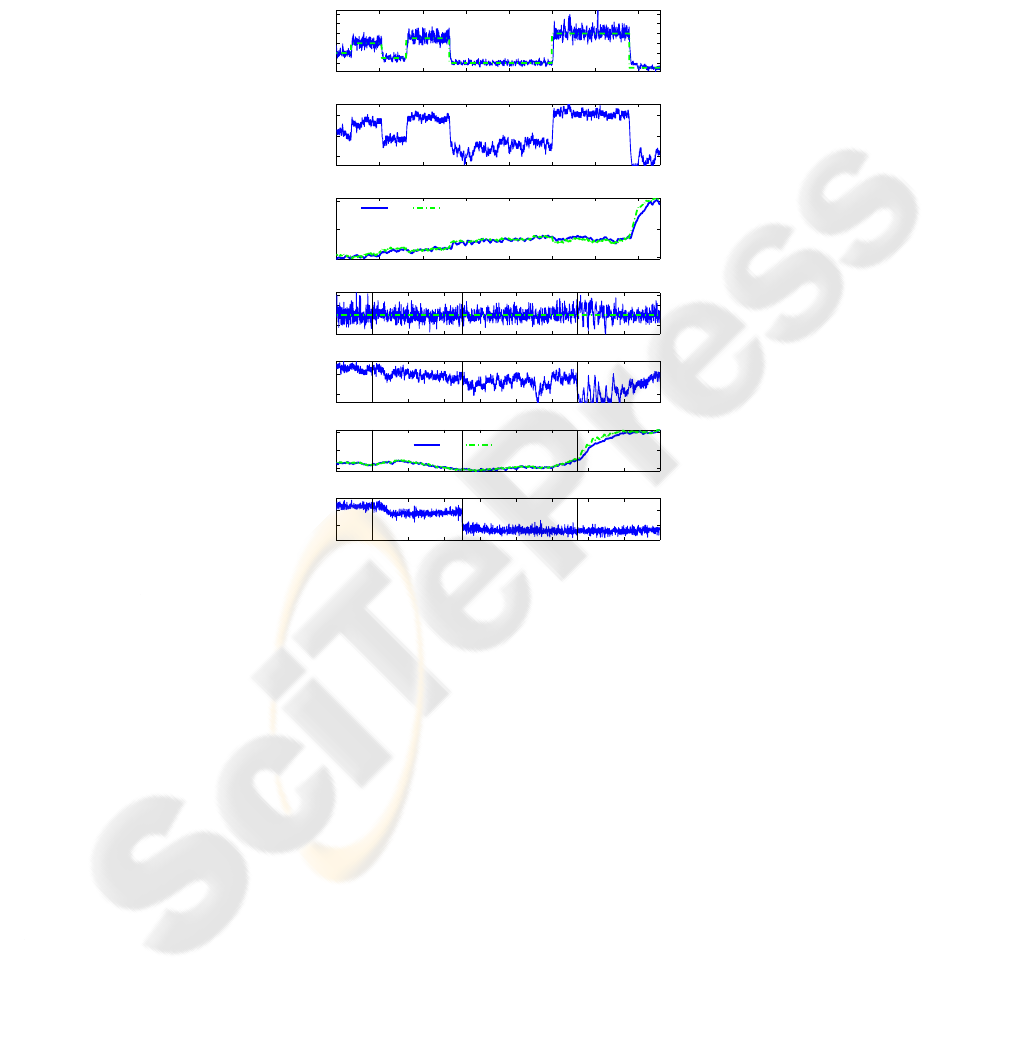
0 200 400 600 800 1000 1200 1400
−2
0
2
4
6
8
Cycle Index [−]
θ
50
[Deg]
0 200 400 600 800 1000 1200 1400
560
580
600
Cycle Index [−]
θ
IVC
[Deg]
0 200 400 600 800 1000 1200 1400
110
120
130
Cycle Index [−]
T
in
[C]
Data Set Point
0 200 400 600 800 1000 1200 1400 1600
0
1
2
3
θ
50
[Deg]
0 200 400 600 800 1000 1200 1400 1600
560
580
θ
IVC
[Deg]
0 200 400 600 800 1000 1200 1400 1600
110
120
130
T
in
[C]
Data Set Point
0 200 400 600 800 1000 1200 1400 1600 1800
2.5
3
3.5
x 10
5
Cycle Index [−]
IMEP
n
[Pa]
Engine Speed
Fuel Energy
EGR Level
Fig.1. Results of consecutive set-point changes (upper) and response to disturbances (lower)
[63].
A cycle-resolved model of HCCI presented in [64] was used to design model pre-
dictive controllers. The controlled output was the crank angle of 50 % burnt fuel (here
denoted θ
50
). The control signals were the inlet air temperature and the crank angle of
inlet valve closing. A fast thermal management system was used to obtain fast intake
temperature actuation.
As witnessed by Fig 1, successful model-based control was accomplished both for
setpoint tracking and disturbance rejection.
4 Conclusions
In addition to aspects of modeling related to thermodynamics, chemical combustion
kinetics, and engine operation, careful attention is required for control-oriented com-

bustion modeling and the interactions among dynamics, control, thermodynamics and
chemical combustion properties. Modeling of engine-load transients as well as ther-
mal transients also belong to this important domain of modeling (Fig. 1). Progress in
this area is important and necessary for successful and robust control such as model-
predictive control.
Within the project a cycle-resolved, physics-based, model of HCCI has been de-
veloped. The model includes a low-complexity model of the cylinder wall temperature
dynamics in order to capture the relevant time-scales of transient HCCI when only small
amounts of hot residuals are trapped in the cylinder. The temperature evolution of the
gas charge is modeled as isentropic compression and expansion with three heat transfer
events during each cycle.
Recently, research focused on design and evaluation of model predictive controllers
based on linearizations of the model. The considered control signals were the inlet
valve closing and the intake temperature. Simulations were used for the initial control
design and the resulting controller was tested experimentally. The control performance
was evaluated in terms of response time to set-point changes and the resulting output
variance.
It was found that a comparable decrease in the output variance in some operating
points could be achieved either by introducing a disturbance model or by changing
linearization. All tested set-pointchanges were accomplishedwithin 20 engine cycles or
less. Only minor changes to the intake temperature were required for moderate changes.
The closed-loop system showed good robustness towards disturbances in engine speed,
injected fuel energy, and the amount of recycled exhaust gases.
Acknowledgements
This research was supportedby the CompetenceCenter of Combustion Processes(KCFP)
Project Closed-LoopCombustion Control, Swedish Energy Administration (Ref. 22485-
1).
This research was partially done in the framework of the HYCON Network of Ex-
cellence, contract number FP6-IST-511368.
The authors would like to thank Johan Bengtsson, Daniel Blom, Kent Ekholm,
Bengt Johansson, Maria Karlsson, Petter Strandh for cooperation on HCCI modeling
and control.
References
1. Agrell, F., H.-E.
˚
Angstr¨om, B. Eriksson, and J. Wikander. (2003). Transient control of HCCI
through combined intake and exhaust valve actuation. SAE Technical Papers 2003-01-3172.
2. Ahmed, S., T. Tzeuch, P. Amn´eus, E. Blurock, H. Soyhan, and F. Mauss (2003). PLANET
D4 report, The European Community.
3. Amn´eus, P. (2002). Homogeneous Ignition—Chemical Kinetic Studies for IC-Engine Appli-
cations. PhD thesis, Div. Combustion Physics, Lund University, Lund, Sweden
4. Bemporad, A., F. Borelli, and M. Morari (2002). Model predictive control based on linear
programming-the explicit solution. IEEE Trans. Automatic Control, 47:1974–1985.

5. Bengtsson, J., M. G¨afvert, and P. Strandh (2004) Modeling of HCCI engine combustion for
control analysis. In Proc. Conf. Decision and Control (CDC 2004), Bahamas, Dec 2004.
6. Bengtsson, J., P. Strandh, R. Johansson, P. Tunest˚al, and B. Johansson (2004). Closed-loop
combustion control of homogeneous charge compression ignition (HCCI) engines dynamics.
Int. J. Adaptive Control and Signal Processing, 18:167–179.
7. Bengtsson, J., P. Strandh, R. Johansson, P. Tunest˚al, and B. Johansson (2004). System iden-
tification of homogenous charge compression ignition (HCCI) engine dynamics. In IFAC
Symp. Advances in Automotive Control (AAC04), Salerno, Italy, April 19-23, 2004.
8. Bengtsson, J., P. Strandh, R. Johansson, P. Tunest˚al, and B. Johansson (2006). Hybrid control
of homogeneous charge compression ignition (HCCI) engine dynamics. Int. J. Control,
79(5):422–448.
9. Bengtsson, J., P. Strandh, R. Johansson, P. Tunest˚al, and B. Johansson (2007). Hybrid mod-
elling of homogeneous charge compression ignition (HCCI) engine dynamic—A survey.
International Journal of Control, 80(11):1814–1848, November 2007.
10. Bitar, E. Y., H. J. Schock, and A. K. Oppenheim (2006). Model for control of combustion in
a piston engine. SAE Technical Papers 2006-01-0401.
11. Blom, D., M. Karlsson, K. Ekholm, P. Tunest˚al, and R. Johansson (2008). HCCI engine
modeling and control using conservation principles. In SAE World Congress, SAE Technical
Papers 2008-01-0789, Detroit, MI, April 2008.
12. Chase Jr., M. W. , C. A. Davies, J. R. Davies Jr., D. J. Fulrip, R. A. McDonald, and A. N.
Syverud (1985). JANAF thermochemical tables, 3rd ed. J. Physical and Chemical Reference
Data, 14, Supplement 1.
13. Chiang, C.-J. , A. G. Stefanopoulou, and M. Jankovic (2007). Nonlinear observer-based con-
trol of load transitions in homogeneous charge compression ignition engines. IEEE Trans.
Control Systems Technology,, 15(3):438–448.
14. Christensen, M., P. Einewall, and B. Johansson (1997). Homogeneous charge compression
ignition (HCCI) using isooctane, ethanol and natural gas—A comparison with spark-ignition
operation. SAE Technical Papers 972874.
15. Christensen, M., A. Hultqvist, and B. Johansson (1999). Demonstrating the multi-fuel ca-
pability of a homogeneous charge compression ignition engine with variable compression
ratio. SAE Technical Papers 1999-01-3679.
16. Colin, O., A. Pires da Cruz, and S. Jay (2005). Detailed chemistry-based auto-ignition model
including low temperature phenomena applied to 3-D engine calculations. Proc. Combustion
Institute, 30:2649–2656.
17. Cook, D. J., H. Pitsch, J. H. Chen, and E. R. Hawkes (2007). Flamelet-based modeling of
auto-ignition with thermal inhomogeneities for application to HCCI engines. Proc. Combus-
tion Institute, 31:2903–2911.
18. Curran, H. J., P. Gaffuri, W. J. Pitz, and C. K. Westbrook (2002). A comprehensive modeling
study of isooctane oxidation. Combustion and Flame, 129:253–280.
19. Egeland, O., and J. Tommy Gravdahl (2002). Modeling and Simulation For Automatic Con-
trol. Marine Cybernetics, Trondheim, Norway.
20. Eriksson, L., L. Nielsen, and M. Glavenius (1997). Closed loop ignition control by ionization
current interpretation. SAE Technical Papers 970854.
21. Fieweger, K., R. Blumenthal, and G. Adomeit (1997). Self-ignition of s.i. engine model
fuels: A shock tube investigation at high pressure. Combustion and Flame, 109:599–619.
22. Franke, A. (2002). Characterization of an Electrical Sensor for Combustion Diagnostics.
PhD thesis, ISRN LUTFD/TFCP–80–SE, Dept. Physics, Lund University, Lund, Sweden.
23. Gavillet, G. G., J. A. Maxson, and A. K. Oppenheim (1993). Thermodynamic and thermo-
chemical aspects of combustion in premixed charge engines revisited. SAE Technical Papers
930432, 20.

24. Gillbrand, P., H. Johansson, and J. Nytomt (1987). Method and apparatus for detecting ion
current in an internal combustion engine ignition system. Technical report, U.S. Patent No.
4,648,367.
25. Gordon, S., and B. J. McBride (1996). Computer Program for Calculation of Complex
Chemical Equilibrium Compositions and Applications: I. Analysis; II. Users Manual and
Program Description. NASA Reference Publication 1311, Oct. 1994; June 1996.
26. Halstead, M. P., L. J. Kirsch, and C. P. Quinn (1977). The auto-ignition of hydrocarbon
fuels at high temperatures and pressures—Fitting of a mathematical model. Combustion and
Flame, 30:45–60.
27. Haraldsson, G., P. Tunest˚al, B. Johansson, and J. Hyvonen (2003). HCCI combustion phasing
with closed-loop combustion control using variable compression ratio in a multi-cylinder
engine. SAE Transactions, 112(4):1233–1245. (also JSAE 20030126).
28. Haraldsson, G., P. Tunest˚al, B. Johansson, and J. Hyvonen (2004). HCCI closed-loop com-
bustion control using fast thermal management. SAE Transactions, 113(3):599–610.
29. Heywood, J. B.. (1988). Internal Combustion Engine Fundamentals. McGraw-Hill, N.Y.
30. Hultqvist, A., M. Christensen, B. Johansson, A. Franke, M. Richter, and M. Ald´en (1999).
A study of the homogeneous charge compression ignition combustion process by chemolu-
minescence imaging. SAE Technical Papers 1999-01-3680.
31. Ishibashi, Y. and M. Asai (1996). Improving the exhaust emissions of two-stroke engines by
applying the activated radical combustion. SAE Technical Papers 960742.
32. Chiang, C. J., and A.G. Stefanopoulou (2006). Sensitivity analysis of combustion timing and
duration of homogeneous charge compression ignition (HCCI) engines. In Proc. 2006 Am.
Control Conf., Minneapolis, MN, USA, June 2006.
33. Johansson, R. (1993). System Modeling and Identification. Prentice Hall, Englewood Cliffs,
New Jersey.
34. Johansson, R., and A. Rantzer (2003). Nonlinear and Hybrid Systems in Automotive Control.
Springer-Verlag, London. ISBN 1-85233-652-8.
35. Maciejowski, J., (2002). Predictive Control with Constraints. Prentice Hall, Pearson Educa-
tion, England.
36. Mack, J. H., D. L. Flowers, B. A. Buchholz, and R. W. Dibble (2005). Investigation of HCCI
combustion of diethyl ether and ethanol mixtures using carbon 14 tracing and numerical
simulations. Proc. Combustion Institute, 30:2693–2700.
37. Maroteaux, F., and L. Noel (2006). Development of a reduced n−heptane oxidation mecha-
nism for HCCI combustion modeling. Combustion and Flame, 146:246–267.
38. Martinez-Frias, J. S., M. Aceves, D. L. Flowers, J. R. Smith, and R. W. Dibble (2000). HCCI
engine control by thermal management. SAE Technical Papers 2000-01-2869.
39. Ming Jia and Maozhao Xie (2006). A chemical kinetics model of iso-octane oxidation for
HCCI engines. Fuel, pages 2593–2604.
40. Olsson, J.-O. ,P. Tunest˚al, G. Haraldsson, and B. Johansson (2001). A turbo charged dual
fuel HCCI engine. SAE Technical Papers 2001-01-1896.
41. Olsson, J.-O. , P. Tunest˚al, and B. Johansson (2001). Closed-loop control of an HCCI engine.
SAE Technical Papers 2001-01-1031.
42. Onishi, S., Souk Hong Jo, K. Shoda, Pan Do Jo, and S. Kato (1979). Active thermo-
atmosphere combustion (ATAC)—A new combustion process for internal combustion en-
gines. SAE Technical Papers 790501.
43. Oppenheim, A. K., A.L. Kuhl, A. K. Packard, J. K. Hedrick, and W. P. Johnson (1996).
Model and control of heat release in engines. SAE Technical Papers SAE 960601, Engine
Combustion and Flow Diagnostics, SAE SP-1157:15–23.
44. Rausen, D. J., A. G. Stefanopoulou, J.-M. Kang, J. A. Eng, and T. W. Kuo (2004). A mean-
value model for control of homogeneous charge compression ignition (HCCI) engines. In
Proc. 2004 Am. Control Conf. (ACC04), Boston, Massachusetts, USA, July 2004.

45. Ravi, N., M. J. Roelle, A. F. Jungkunz, and J. C. Gerdes (2006). A physically based two-state
model for controlling exhaust recompression HCCI in gasoline engines. In Proc. IMECE’06,
Chicago, IL, USA, November 2006.
46. Richter, M., A. Franke, J. Engstr¨om, A. Hultqvist, B. Johansson, and M. Ald´en (2000). The
influence of charge inhomogeneity on the HCCI combustion process. SAE Technical Papers
2000-01-2868.
47. Sankarana, R., G. I. Hong, E. R. Hawkes, and J. H. Chen (2005). The effects of non-uniform
temperature distribution on the ignition of a lean homogeneous hydrogen-air mixture. Proc.
Combustion Institute, 30:875–882.
48. Semenov, N. N. (1934). Chain Reactions. Goskhimtekhizdat, Leningrad. [transl.: Chemical
Kinetics and Chain Reactions, Oxford University Press, 1935].
49. Shahbakhti, M., and R. Koch (2007). Control oriented modeling of combustion phasing for
an HCCI engine. In Proc. 2007 Am. Control Conf., New York City, NY, USA, July 2007.
50. Shaver, G. M., J. C. Gerdes, P. Jain, P. A. Caton, and C. F. Edwards (2002). Modeling for
control of HCCI engines. In Proc. American Control Conference, pag749–754, Denver, CO.
51. Shaver, G. M., J. C. Gerdes, and M. Roelle (2004). Physics-based closed-loop control of
phasing, peak pressure and work output in HCCI engines utilizing variable valve actuation.
In Proc. American Control Conference, pages 150–155, Boston, MA.
52. Shaver, G. M., M. Roelle, and J. C. Gerdes (2005). Decoupled control of combustion timing
and work output residual-affected HCCI engines. In Proc. 2005 American Control Conf.,
pages 3871–3876, Portland, OR, June 8-10 2005.
53. Shaver, G. M., M. Roelle, and J. C. Gerdes (2006). Two-input two-output control model of
HCCI engines. In Proc. 2006 American Control Conf., pages 472–477, Minneapolis, MN,
June 14-16 2006.
54. Shaver, G. M., M. J. Roelle, and J. C. Gerdes (2006). Modeling cycle-to-cycle dynamics
and mode transition in HCCI engines with variable valve actuation. Control Engineering
Practice, 14:213–222, 2006.
55. Sj¨oberg, M., and J. E. Dec (2004). Comparing enhanced natural thermal stratification against
retarded combustion phasing for smoothing of HCCI heat-release rates. SAE Technical Pa-
pers 2004-01-2994.
56. Sj¨oberg, M., and J.E. Dec (2003). Combined effects of fuel-type and engine speed on intake
temperature requirements and completeness of bulge-gas reactions for HCCI combustion.
SAE Technical Papers 2003-01-3173.
57. Stockinger, M., H. Sch¨apert¨ons, and P. Kuhlmann (1992). Versuche an einem gemis-
chansaugenden Verbrennungsmotor mit Selbstz¨undung. MTZ, 53:80–85.
58. Strandh, P., J. Bengtsson, M. Christensen, R. Johansson, A. Vressner, P. Tunest˚al, and B. Jo-
hansson (2003). Ion current sensing for HCCI combustion feedback. SAE Technical Papers
2003-01-3216.
59. Suzuki, H., N. Koike, H. Ishii, and M. Odaka (1997). Exhaust purification of Diesel engines
by homogeneous charge with compression ignition. SAE Technical Papers 970315.
60. Tanaka, S., F. Ayala, and J. C. Keck (2003). A reduced chemical kinetic model for HCCI
combustion of primary reference fuels in a rapid compression machine. Combustion and
Flame, 133:467–481.
61. Thring, R. H. (1989). Homogeneous-charge compression-ignition (HCCI) engines. SAE
Technical Papers 892068.
62. Turns, S. R., (1996). An Introduction to Combustion—Concepts and Applications. McGraw-
Hill, Singapore. (2nd ed. 2000).
63. Widd, A., K. Ekholm, P. Tunest˚al, and R. Johansson (2009). Experimental evaluation of
predictive combustion phasing control in an HCCI engine using fast thermal management
and VVA. In Proc. 18th IEEE Conf. Control Applications, St. Petersburg, Russia, July 2009.

64. Widd, A., P . Tunest˚al, and R. Johansson (2008). Physical modeling and control of homoge-
neous charge compression ignition (HCCI) engines. In Proc. 47th IEEE Conf. Decision and
Control, Cancun, Mexico, December 2008. pp. 5615-5620.
65. Wiebe, I. I. (1970). Brennverlauf und Kreisprozessrechnung. VEB Verlag Technik, Berlin.
66. Woschni, G. (1967). A universally applicable equation for instantaneous heat transfer coef-
ficient in the internal combustion engine. SAE Technical Papers 670931.
