
ONTOLOGY DEVELOPMENT FOR MODEL-DRIVEN DESIGN
IN KNOWLEDGE BASED ENGINEERING
Stefan van der Elst and Michel van Tooren
Design of Aircraft and Rotorcraft, Delft University of Technology, Kluyverweg 1, 2629 HS Delft, The Netherlands
Keywords: Knowledge Based Engineering, Knowledge base, Ontology development, Routine design, Design
automation, Assignment problem, Wire harness design.
Abstract: Knowledge is a vital component of engineering design. Computer systems enriched with logic and
engineering knowledge can support engineering design by automating routine configuration design
processes. This automation is well structured in the framework concept of a Design and Engineering
Engine, applying Knowledge Based Engineering techniques. The lack of recognized development
methodologies implies significant investments for the development and maintenance of Design and
Engineering Engines. To alleviate the required effort an ontology for engineering knowledge is being
developed. To that end, a classification of configuration design processes is proposed as well as a
classification of knowledge elements. The resulting knowledge repository can be considered a Domain
Specific modelling Language. To validate the proposed ontology, a case study is presented, addressing an
assignment problem in the field of wire harness design. Using the Domain Specific modelling Language, the
source code for the product model can be generated automatically using a model-driven approach.
1 INTRODUCTION
Modern-day market dynamics and the current
economic climate require an increasing industrial
focus on lifetime cost reduction, shorter time-to-
market and greater product differentiation. In order
to achieve the associated improvement in product
development and remain competitive in a globalized
market, the engineering industry needs more cutting
edge productivity enhancements.
While the continuous improvement of the
production process by the application of lean
principles is making good progress, the increase of
the effectiveness and efficiency of the engineering
processes by adopting lean principles is still in its
infancy. The next step in the efficiency increase is to
reuse corporate engineering knowledge to a larger
extent (Drucker, 2001) (Quinn, 1992) .
Knowledge is a vital component of engineering
design and significant reductions in costs and
product development time can be realized if
engineering knowledge would be reused to a larger
extent and more often. Where previously the
geometric model took a central position in product
development, today design knowledge should have
the focus: human intellect should be managed and
engineered as a key business asset (Drucker, 2001).
Computer systems enriched with logic and
engineering knowledge can support engineering by
automating repetitive and time-consuming routine
design processes. This reuse of knowledge decreases
the intellectual resources required during product
development processes and relieves engineers from
repetitive and tedious design activities, making more
time available to exploit their creativity and
engineering skills. Knowledge Based Engineering
(KBE) is known as the cross product of engineering
and Knowledge Based Systems (KBS) and enables
this automation of routine engineering design
processes (La Rocca, 2002). By defining parametric
generative models of systems, KBE enables
designers to explore the design space more
efficiently by automatically generating and
analyzing new design configurations and instances.
Although huge time and cost benefits can be
gained, KBE techniques are not yet widely adopted
by industry. Efficient utilisation of knowledge in
software implies significant investments for the
development and support of KBE applications due to
a lack of acknowledged methodologies. In addition,
developed applications are frequently considered
261
van der Elst S. and van Tooren M. (2009).
ONTOLOGY DEVELOPMENT FOR MODEL-DRIVEN DESIGN IN KNOWLEDGE BASED ENGINEERING.
In Proceedings of the International Conference on Knowledge Engineering and Ontology Development, pages 261-268
DOI: 10.5220/0002305102610268
Copyright
c
SciTePress

‘black boxes’, since the applied methods are poorly
documented and the source code is inexpressive.
This has a negative effect on the maintainability and
the extendibility of such applications.
In this paper an ontology, a structure of the
existing knowledge categories and their relations, is
proposed to support the implementation of a second
generation KBE systems in industry. The ontology
for engineering knowledge is geared towards routine
design processes. It entails a categorisation of
knowledge elements into product versus process
knowledge and domain-specific versus problem-
specific knowledge. The proposed ontology aims to
achieve better use of intellectual human resources as
tangible asset: it enables the reuse of domain
knowledge across multiple design problems as well
as sharing problem related knowledge across
multiple application fields. Repositories of
knowledge based on the proposed ontology provide
a platform to rapidly develop design models for
KBE applications, reusing the knowledge already
captured and formalised.
2 ENGINEERING DESIGN
Engineering design can be considered a deliberate
search problem in a solution space for artefacts that
satisfy functional needs within a set of constraints.
The solution space or design space can be
considered a range of available components and a
set of relations between those components in order
to form artefacts. Although the solution space can
encompass an infinite number of solutions, in
general only a small number of artefacts form
feasible and satisfying, not to mention optimal,
solutions. Such a solution to the design problem
entails a collection of components and their
relations, that together provide a complete
specification of the system that delivers the
requested functions and satisfies the constraints
(Chandrasekaran, 1990).
2.1 Design Problem Categorisation
Design problem solving can be divided into routine
and non-routine design activities, based on the
identification and availability of the knowledge
involved in the design process. Brown and
Chandrasekaran identified three classes of design,
related to the level of ‘routineness’ (Brown, 1989):
For the first class, Class 1 Design, neither all
possible decompositions of the artefact nor the
approach to solve the design problem is
known in advance.
For Class 2 Design, the possible
configurations and components are known,
however the problem solving strategy is not.
For the third class, Class 3 Design, all possible
configurations, components and design
variables are known. Furthermore, the
problem solving approach is acknowledged,
resulting in the availability of so-called design
plans.
The three abovementioned classes of design
correspond to the general acknowledged categories
of design into routine design, innovative design and
creative design as introduced by Gero (Gero, 1993).
Here, routine design concern designs that fit within
the space of previous solutions. Therefore in routine
design the components and their variables, the
constraints for those variables and the type of
requirements are known in advance. Innovative
designs are based on known design options, however
the applicable range of values for the variables is
extended. Creative design involves the definition of
new components, variables or relations between
components. Here, neither all components nor the
problem solving strategy is known in advance.
Innovative and creative design together make up the
non-routine design problems. Typically, a
development process for a new product will
encompass routine, innovative and creative design
activities. The remainder of this paper will focus on
routine design problems.
2.2 Routine Design Problems
Judged by the type of components and the assembly
of the artefact, different dimensions of routine
design problems can be distinguished (Wielinga,
1997). Figure 1 summarizes the most common types
of routine design problems. It should not be
considered an attempt to provide a comprehensive
overview of all routine design problems.
Starting with the most basic form of routine
design, verification problems aim to confirm the
validity of a synthesized artefact, where both the
assembly as well as the components are predefined.
Assignment problems deal with matching sets of
resources (components in product design) with a
fixed collection of subjects, defined as the assembly
outline or skeleton. Example problems are the
assignment of airplanes to terminal gates or the
assigned queuing of travellers at airport security
gates. Lay-out design or scheduling problems also
involve fixed sets of components, but the outline nor
composition of the artefact is known in advance. An
example is the arrangement of machines for a
factory layout. Parametric design assumes a
KEOD 2009 - International Conference on Knowledge Engineering and Ontology Development
262

predefined assembly and is concerned with the
assignment of values to component parameters in
order to meet the requirements. An example is the
sizing of an structural beam according to a static
load case. Skeletal design is concerned with a
continuous solution space and involves the matching
of parametric components to a given assembly.
Finally, configuration design involves the assembly
of an undetermined set of parametric components to
meet a set of requirements. An example problem is
the design of an aircraft wing, where the
composition as well as the values for the parameters
belonging to the different components shall be
determined (e.g. material, number of ribs and
thickness of the spar web).
Configuration design is closest to non-routine
design problems and differs from innovative design
by the constrained values ranges for the design
parameters for which the problem solving strategy
holds.
The provided types of design problems are listed
in order of increasing complexity. Both the amount
of applicable components and the collection of
settable parameters add to the degrees of freedom of
the assembly enlarging the valid solution space.
Since the approach, the components and the
requirements are known for routine design problems
they are particularly well suited for design
automation using KBE techniques (Chandrasekaran,
1990).
3 KNOWLEDGE BASED
ENGINEERING
According to La Rocca (Milton, 2008) KBE
concerns the development of software systems to
support engineers, usually design engineers, to
increase their productivity. KBE systems are
considered a subset of Knowledge Based Systems or
Expert Systems dedicated to engineering design and
therefore empowered with Computer Aided Design
(CAD) capabilities. The KBE cornerstones are
considered to be rule-based design, object-oriented
programming, and parametric CAD (La Rocca,
2005). KBE systems are able to capture and reuse
engineering product and process knowledge to
automatically solve engineering design problems
involving the manipulation of geometry, product
configuration and analyses and computations.
The main objective of KBE is reducing time and
cost in product development by means of the
following:
Automation of recurring and routine
engineering design activities. This mainly
involves the automation of the preceding
routine design problems for which all related
knowledge can be captured and formalised.
Due to the nature of product development, it
best suits detailed design.
Support and integration of multidisciplinary
design and optimisation problems. It
facilitates innovative and creative design since
it concerns the definition of new components,
design parameters and configurations in order
to create novel solutions and investigate
multiple ‘what-if’ scenarios. It mainly applies
to the conceptual and preliminary phases of
the design process.
The automation of engineering design problems
is well structured using the framework concept of a
Design and Engineering Engine.
3.1 Design and Engineering Engine
A Design and Engineering Engine (DEE) is defined
as an advanced design environment that supports
and accelerates the design process of
multidisciplinary product families through the
automation of routine and recurring design activities
(La Rocca, 2002). Figure 2 shows a schematic
drawing of the DEE concept for the aerospace
sector.
The main components of the DEE are the
Initiator, the Multi-Model Generator, the Analysis
tools and the Converger & Evaluator.
Figure 1: The dimensions of components and assembly drive the different types of routine design.
ONTOLOGY DEVELOPMENT FOR MODEL-DRIVEN DESIGN IN KNOWLEDGE BASED ENGINEERING
263
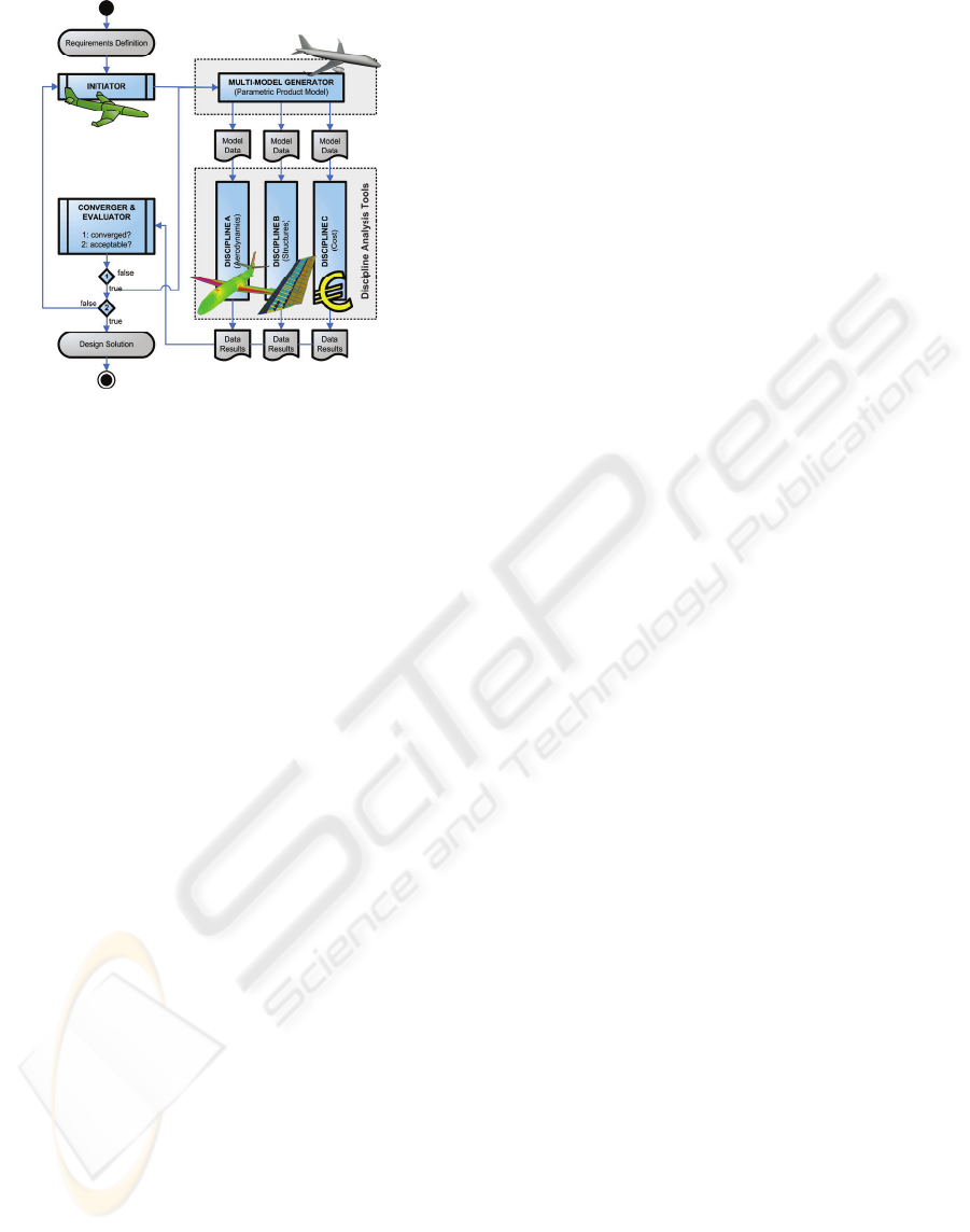
Figure 2: The Design and Engineering Engine concept.
The Initiator is responsible for providing feasible
initial values for the design parameters in order to
instantiate the generative product model.
The Multi-Model Generator (MMG) is
responsible for instantiation of the generative
product model and extracts different views on the
model to facilitate the discipline specialist tools. The
MMG is where the KBE cornerstones object-
oriented programming, parametric CAD and rule-
based design are encapsulated. It forms the heart of
the DEE.
The Analysis (discipline specialist) tools are
responsible for evaluating one or several aspects of
the design in their domain or discipline (e.g.
structural response, cost or manufacturability).
The Converger & Evaluator is responsible for
checking convergence of the design solution,
compliance of the system’s properties with the
requirements and generation of a new design vector.
The framework concept of the DEE provides
engineers with a guided control mechanism to search
the solution space. The elements of the DEE are
addressed iteratively in order to define a feasible
design solution satisfying the requirements
definition. To that purpose, the framework also
offers communication capabilities through the
coupling of software agents using a Multi-Agent
Task Environment (Berends, 2008).
3.2 Multi-Model Generator
Design engineers like to think of a system or artefact
as a collection of components providing conceptual
solutions to fulfil functional requirements. To
support engineers in their perspective of design the
MMG provides a catalogue of parametric building
blocks, called High Level Primitives (HLPs) (La
Rocca, 2005). They represent classes of components
containing product related knowledge that drives the
instantiation of individual components by assigning
values to the parameters. The HLPs can be
individually sized and assembled to compose a large
number of different product configurations.
Therefore an assembly of HLPs can be considered a
generative product model, capable of generating
parametric geometric representations for families of
products with a similar composition. Next to the
HLPs Capability modules (CMs) form the other
main element in the MMG. CMs are ‘report writers’
applied to generate specific aspect views of a
system, e.g. an aerodynamic mesh or a Finite
Element model of an aircraft wing. The CMs
facilitate the analysis tools representing the various
engineering disciplines.
Consequently, the concept of the MMG supports
a modular approach to engineering design problems
and offers the designers a more effective approach to
visualize their ideas, compared to the approach
offered by conventional CAD systems. The HLPs
are considered principal elements storing
engineering knowledge. Instead of geometric
primitives incorporated by CAD systems, the MMG
is oriented to knowledge primitives.
4 DESIGN KNOWLEDGE
Knowledge is defined as the state of knowing about
a particular fact or situation and how to act
accordingly (Hornby, 2000). Most engineering
knowledge is not an explicitly and consistently
defined collective, but instead is concealed in the
processes, products, language and human specialists
themselves which define the local engineering
practices. This expertise should be transformed into
a well-defined body of knowledge suitable for
encoding into High Level Primitives and utilisation
in KBE systems.
When developing intelligent systems, the
developers or knowledge engineers should have a
good understanding of the various types of relevant
knowledge and representation techniques that suit
the application. Knowledge can be organised in
many different ways, not one of them being a
supreme theory that addresses the management of all
human intellect. Before engineering knowledge can
be utilised in KBE systems, it is therefore important
to get a thorough and formal description of the
knowledge involved.
4.1 Knowledge Base
In order to support the reuse of engineering
knowledge by KBE techniques, knowledge is
KEOD 2009 - International Conference on Knowledge Engineering and Ontology Development
264
initially captured and stored in a knowledge base, a
repository containing a formal description of
knowledge representing the expertise of a particular
domain (Milton, 2008). A knowledge base has
multiple main functions. In order to alleviate the
effort involved in developing KBE applications the
knowledge should be intelligible to both engineers
and software agents. It should therefore incorporate
two different perspectives on the design process:
Provide a comprehensive overview of the
routine design process (IST);
Provide insight in and understanding of the
KBE application and applied methods (SOL).
The anatomy of a knowledge base is identical to
the structures that underlie human expertise or
psychological registration. Psychologists have found
that this is based on four main elements;
components, attributes, values and relations (Milton,
2008). According to the Methodology and tools
Oriented to KBE Applications (MOKA) a
knowledge base should contain two primary types of
diagrams to visualise these knowledge components
(Stokes, 2001); process models and product models.
The process model is a process flow chart or activity
diagram. The process model focuses on the activities
performed by actors and is oriented to the ‘input-
behaviour-output’ perspective. It mainly contains
procedural knowledge. The product model is
considered a composition tree. It is a product-centric
and object-oriented model providing a hierarchical
decomposition of the system into subassemblies and
components. It is oriented to the ‘object-relation-
object’ perspective and mainly contains conceptual
knowledge.
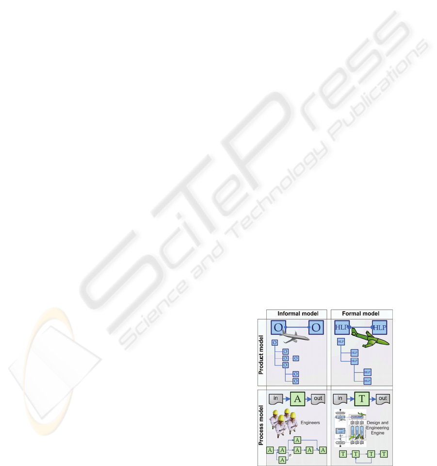
Using both types of diagrams, two distinct
segments of the knowledge base can be built. This
partition complies with the contrasting perspectives
(IST and SOL). The segments are referred to as the
informal model and the formal model.
The informal model is used to capture and
validate the knowledge in close corporation with the
domain experts. The engineering knowledge is
represented using natural language, terminology
from the domain under consideration and pre-
defined forms. The informal model acts as an
analysis instrument, developed to obtain
understanding of the domain. The objective of the
informal part of the knowledge base is to verify the
correctness and completeness of the knowledge
involved in the routine design process. The concepts
in the domain of interest are organized without any
consideration of their role in the KBE application.
The formal model provides a more formal view of
the problem geared towards the involved knowledge
engineers, developers and software agents. The
formal model acts as blueprint for the design of the
KBE application and uses the elements of the
informal model to define reusable building blocks
representing predeveloped modules of knowledge.
The elements of the formal model form a
specification for the software classes that
encapsulate the engineering knowledge in the DEE.
These elements are indeed the HLPs, specified and
assembled to represent the generative product model
of the MMG. Frame representations are used to
define the characteristic attributes and specify their
values or parameters. Besides, CMs are defined in
accordance with the process flow description of the
informal model. The formal model will also define
the type of routine design problem and the
appropriate Problem Solving Method (PSM),
algorithm and optimisation criteria. The source code
for the DEE can be designed based on the formal
model and the model will provide insight in the
composition of and reasoning behind the software
(Larman, 2005) (Evans, 2000).
The different perspectives for the informal and
formal model of the knowledge base require
different structures. Whereas there are several
ontologies to capture engineering knowledge in
general, ontologies specifically built to develop KBE
applications using a model-driven approach are yet
to be determined. Such an ontology is proposed in
the next section. The structures of the informal and
the formal model are sketched in Figure 3.
4.2 Ontology Proposition for KBE
In order to organise a body of knowledge for
utilisation in KBE applications, an ontology, an
armature of the existing knowledge categories and
their relations within a domain, is proposed. It is
based on two orthogonal categories of knowledge.
The first category defines procedural knowledge
versus conceptual knowledge (Stokes, 2001).
Figure 3: Schematic overview of knowledge base with
two-fold structure.
ONTOLOGY DEVELOPMENT FOR MODEL-DRIVEN DESIGN IN KNOWLEDGE BASED ENGINEERING
265
Procedural knowledge concerns processes, tasks and
activities. It describes the conditions, under which
specific tasks are performed, the order in which
tasks are performed and the resources required to
perform tasks. Conceptual knowledge or declarative
knowledge concerns the description of concepts or
components, their relation to one another and their
properties, e.g. the attributes and parameters.
The second category of knowledge distinguishes
problem-solving or problem-specific knowledge
from domain-specific knowledge. Problem-solving
knowledge specifies how to use the factual
knowledge about a domain to construct a solution to
the problem (Chandrasekaran, 1997). Considering
routine design problems, the problem solving
knowledge might concern for example suitable
Problem Solving Methods (PSMs), algorithms and
control regimes for a particular type of routine
design problem. Domain knowledge is defined as
factual knowledge representative for a specific
domain of interest (components, relations,
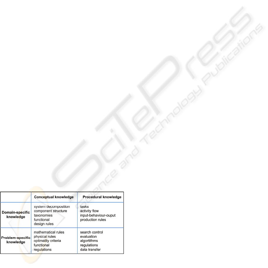
properties, rules etc.). Figure 4 presents an
assortment of different types of knowledge involved
in KBE. Note that there does not exist a clear
division between domain-specific and domain-
independent or problem-specific knowledge. For
example, the elements object, physical object, wing,
delta-wing and composite delta-wing are all
abstractions of the same object in order of increasing
domain-specificity (Chandrasekaran, 1997).
The resulting ontology entails two taxonomic
branches. The first branch allows for the structuring
of domain knowledge; the second branch arranges
problem-solving knowledge. This way, the
knowledge repository enables captured domain
knowledge to be shared and reused across multiple
different design problems, whereas the knowledge
for a particular type of design problem can be shared
and reused across multiple domains.
Figure 4: Classification of knowledge involved in KBE.
5 DOMAIN-SPECIFIC
MODELLING
According to the previous section, a knowledge base
embedding the proposed ontology contains two
disjointed sets of knowledge elements that together
can facilitate the modelling of DEEs. Developers
can select the predeveloped modular HLPs and CMs
and combine them with problem-solving methods to
construct models for new KBE applications.
Furthermore the reuse and extension of the
knowledge elements for future KBE applications or
DEEs is facilitated: the knowledge base can be
applied as an environment to intuitively model and
construct new components (HLPs), configurations or
algorithms for specific design problems. The
predeveloped knowledge elements from the
knowledge base are considered the building blocks
for formal models, like words are used in natural
languages to compose sentences. The knowledge
base, including the proposed ontology is therefore
considered a Domain Specific modelling Language
(DSL).
A DSL enables the abstract representation of
conceptual classes of the problem domain and is
considered a visual dictionary of noteworthy
abstractions, domain vocabulary and knowledge
content of the domain under consideration (Kelly,
2008) (Larman, 2005). While traditional modelling
languages like the Unified Modelling Language
(UML) aim to be as generic as possible to serve a
broad range of domains, a DSL is carefully defined
to allow modelling of systems within a particular
problem domain.
5.1 Model-Driven Design
Since a DSL focuses on a narrow field of application
the elements of the formal model require limited
effort to be mapped one-on-one to equivalent
software classes that will embed the engineering
knowledge in source code. If the ontology of the
knowledge base incorporates the correct syntax for
the programming language of the KBE platform, the
definitions of the knowledge elements also become
intelligible to virtual machines. It has been
demonstrated that dynamic source code generation
can be achieved from the formal model via code
generators (Kelly, 2008) (Van der Elst, 2008a). The
DSL provides a visual representation of elements for
ease of construction. Furthermore it can be reasoned
that the DSL facilitates the model-driven design of
KBE applications thereby increasing the level of
abstraction of the models that define DEEs. Hence
KEOD 2009 - International Conference on Knowledge Engineering and Ontology Development
266

less expertise and effort is required to develop
correct and novel KBE applications.
The concepts of DSL and model-driven design
have been applied to develop a KBE application for
the aircraft wiring harness industry.
6 CASE STUDY: AIRCRAFT
WIRE HARNESS DESIGN
Aircraft electric wiring harnesses can be comprised
of hundreds of cables and ten thousands of wires,
providing electrical connectivity between all the
mission and vehicle systems ensuring sufficient
redundancy and reliability. Aircraft wiring design
has a repetitive, time-consuming and rule-based
nature making it a well-suited domain to implement
KBE techniques. The development of the KBE
application is performed in close corporation with a
main, international partner on the aircraft electric
wiring market, regarding both design and
manufacturing.
For the wiring harness design process, one of the
key opportunities for the application of KBE is the
assignment of signals at disconnects. At the
disconnects, also known as production breaks,
electrical connectors connect the different wiring
harnesses (Figure 5). Each wiring harness connector
can include up to 150 slots, called pins, to
accommodate signals. The pins can vary in size, as
do the wires transferring the individual signals.
This process of pin assignment is considered
routine and time-consuming due to the vast quantity
of signals to be assigned and rework caused by
changing input, e.g. governed by design iterations
for the aircraft structural design. Furthermore
separation of signals across multiple wiring harness
segments is enforced by numerous opposing design
rules and regulations, e.g. redundancy of flight
controls and electro-magnetic compatibility.
The allocation of electrical signals (subjects) to a
collection of conducting pins at disconnects
(resources) is considered a problem of the type
assignment: the outline of the system, the total set of
signals is given whereas the problem solving process
involves the definition of the collection of pins
(distribution, size, position etc.) that can best
accommodate these signals.
Figure 5: Connectors applied at an aircraft wire harness.
6.1 Wire Harness Knowledge Base
An ontology for the wire harness domain is
developed in order to support the design of the KBE
application. The knowledge base and the associated
ontology are developed using the Knowledge
Management (KM) software suite PCPACK 5, using
the Extensible Mark-up Language XML to store the
knowledge. The ontology used to structure the
knowledge base is derived from the MOKA
(meta)ontology which is by itself oriented to the
engineering domain in general.
Besides relationships and attributes, there are
four types of elements constituting the ontology:
objects (components), constraints, activities and
rules. Concerning the pin assignment process, four
main conceptual classes of objects are identified:
signal, production-break, connector and pin. Note
that signal is not a physical object. Next to the
conceptual classes, the ontology also contains the
definition of relevant classes of software objects.
These software classes contain the definition of the
High Level Primitives according to the KBE system.
The KBE system utilized for the development of the
MMG is Genworks’ GDL. Both the conceptual
classes and the software classes can be considered
super-classes of the HLPs, as displayed by the
taxonomy in Figure 6.
The concept of inheritance enables the
integration of relevant attributes for respectively the
wire harness domain and the software development
domain into the class definition of the HLPs. Each
object type has a specific frame structure called
annotation template, used to define the characteristic
properties (attributes) of the class. By specifying the
values of the properties, specific instances of classes
are instantiated.
Instances of the four object classes comprise the
structural composition of the wire harness
production-break and are related by the - has part -
relationship. The geometric representation of the
connector is based on the child ‘back-shell’.
Although the back-shell is a component of a
connector and therefore a conceptual class in the
problem domain, it is not considered a primitive in
the software domain. A back-shell is an instance of
the software class ‘circle’ (geometrical primitive).
By defining new classes, for example rectangular
connectors, additional design options can be defined
and new configurations can be generated. In the
example of rectangular connectors, the class
‘rectangular connector’ would be added to the
knowledge base, while the associated back-shell
becomes an instance of the class ‘box’, another
geometric primitive defined by the GDL software
ONTOLOGY DEVELOPMENT FOR MODEL-DRIVEN DESIGN IN KNOWLEDGE BASED ENGINEERING
267

classes. The pin primitive can be reused to provide
the rectangular connector with a set of contacts.
The application of the functional object-oriented
programming language enables the structure of the
software code to resemble the composition of the
product model in an intuitive and intelligible
manner. The conceptual classes from the problem
domain and the software classes from the software
domain have become each others domain equivalent,
describing identical domain knowledge on different
levels of abstraction. The Knowledge Base acts as
DSL and alleviates the effort required to implement
knowledge into the software code embodying the
HLPs. Hence it decreases the time required for the
development of the application. Furthermore,
engineers are not only capable of operating the
design application; they will also gain better
understanding of the Problem Solving Method the
application uses in order to generate solutions. The
latter has proven of critical importance for the
successful implementation of KBE techniques (Van
der Elst, 2008b).
Using the resulting KBE application, the lead-
time for the pin assignment process is reduced by
approximately 80%.
REFERENCES
Berends, J., Van Tooren, M. and Schut, E., 2008. Design
and Implementation of a New Generation Multi-Agent
Task Environment Framework. 4th AIAA
Multidisciplinary Design Optimization Specialist
Conference, AIAA-2008-2142.
Brown, B., Chandrasekaran, B., 1989. Design Problem
Solving: Knowledge Structures and Control Strategies.
Research notes in Artificial Intelligence. Pitman.
Chandrasekaran, B., 1990. Design Problem Solving: A
Task Analysis. AI Magazine Vol. 11 No. 4. AAAI.
Chandrasekaran, B., Josephson, 1997. The Ontology of
Tasks and Methods. AAAI Technical report SS-97-06.
AAAI.
Drucker, P., 2001. Management challenges for the 21st
century, Butterworth-Heinemann.
Evans, E., 2000. Domain-Driven Design. Addison Wesley.
Gero, J., Maher, M., 1993. Modelling creativity and
knowledge-based creative design. Lawrence Erlbaum
associates.
Hornby, A., 2000. Oxford Advanced Learner’s Dictionary,
Oxford, Oxford University Press, 6th edition.
Kelly, S., Tolvanen, J., 2008. Domain-specific Modeling.
John Wiley & Sons, Inc.
La Rocca, G., Van Tooren, M., 2005. Enabling Distributed
Multidisciplinary Design of Complex Products: A
Knowledge Based Engineering Approach. Journal of
Design Research, Vol.5, No. 3, pp 333-352.
La Rocca, G., Krakers, L., Van Tooren, M., 2002.
Development of an ICAD generative model for
blended wing body aircraft design. 9th AIAA/ISSMO
Symposium on Multidisciplinary Analysis and
Optimization, AIAA-2—2-5447.
Larman, C., 2005. Applying UML and Patterns. Prentice
Hall, 3rd edition.
Milton, N., 2008. Knowledge technologies. Polimetrica.
Quinn, J., 1992. Intelligent enterprise. Free Press.
Stokes, M., 2001. Managing Engineering Knowledge,
MOKA: ‘Methodology and Tools Oriented to
Knowledge Based Engineering Applications’.
Professional Engineering Publishing Ltd.
Van der Elst, S., Van Tooren, M., 2008. Domain Specific
Modelling Languages to Support Model-Driven
Engineering of Aircraft Systems. 26
th
International
Congress of the Aeronautical Sciences.
Van der Elst, S., Van Tooren, M, and Vermeulen, B.,
2008. Application of a Knowledge Based Design
Methodology to Support Fuselage Panel Design.
RAeS/CEAS Aircraft Structural Design Conference.
Van Tooren, M., Van der Elst, S. and Vermeulen, B.,
2009. Structured Design Automation. CIRP Integrated
Product-Service System.
Wielinga, B., Schreiber, G., 1997, Configuration-Design
Problem Solving. AI in Design.
ob
j
ect classes
conce
p
tual classes
p
in
p
roduction-brea
k
si
g
nal
connector
software classes GDL Ob
j
ects
g
eom-base base-ob
j
ect
circle
p
in
p
roduction-brea
k
connector
si
g
nal
Figure 6: Partial knowledge base taxonomy encompassing conceptual classes and software classes.
KEOD 2009 - International Conference on Knowledge Engineering and Ontology Development
268
