
A NOVEL DEVICE FOR MEASURING MECHANICAL
IMPEDANCE DURING DYNAMIC TASKS
Hossein Mousavi Hondori and Ling Shih-Fu
School of Mechanical and Aerospace Engineering, Nanyang Technological University,50 Nanyang Avenue, Singapore
Keywords: Dynamic measurement, Assessment of human motor function, Rehabilitation, Mechanical impedance.
Abstract: Mechanical impedance is an important factor that the central nervous system takes into account while
coordinating a motion. This research work thus aims to develop a new measurement for monitoring
dynamic changes of mechanical impedance. The method is introduced and validated in the context. The
results show that device correctly measures the dynamic force and impedance of an eccentric linear spring.
Furthermore, 62 measurement trails on two human subjects (31 trials on each) confirmed that the value of
mechanical impedance changes with adaptation. Finally, we propose a method for the assessment of motor
recovery in the stroke patients undergoing rehabilitation sessions.
1 INTRODUCTION
Assessment of human motor function has remained a
challenge for years; this is because of the complexity
of human brain and the subjective nature of the
assessment. On the other hand with its numerous,
important applications such as assessment of
functional capabilities in post-stroke rehabilitation,
motor function assessment undeniably needs
improvements and new methods. Although several
scoring methods such as Fugl-Meyer (Fugl-Meyer et
al, 1975) or NIH stroke scale (Goldstein et al, 1989)
already exist, they are generally subjective or
qualitative; thus not quite suitable for accurate and
scientific studies of motor functions. For clinical
purposes, though, these methods are still widely
used because of their simplicity. Researchers
recently tried to use robots for the assessment
besides the physical therapy (Palazzolo et al, 2007)
and (Loureiro et al, 2003). Their robots were
basically designed for performing physical therapy
exercises and because of the capabilities of a robot
(Palazzolo et al, 2007) they tried to use the same
robot for assessment purposes. Having measured
forces with respect to displacement, they measured
stiffness of the arm. They assumed a two-DoF model
of mass-spring-damper for the arm and tried to
estimate stiffness, mass, and damping matrices.
However, their method was not a direct, real time,
and in-situation measurement. On the other hand, a
robot might be very complicated and expensive;
setup and maintenance of it can be very difficult as
well. Hence, there still remains a room for a more
reliable, convenient, and efficient tool for the
assessment of motor function. Furthermore, what the
robot measures is also a very important issue for the
assessment.
Hogan (Hogan, 1984) showed that the value of
mechanical impedance for the upper arm, which is
set at the elbow joint, is very important. He
examined the postulate that antagonist muscle’s co-
activation is to generate mechanical impedance and
therefore this is necessary to perform some tasks. A
typical case with necessity of the antagonist
activation is performing a dynamically unstable
task. Burdet (Burdet et al, 2001) showed that human
learns to stabilize unstable dynamics by optimizing
mechanical impedance. Darainy (Darainy et al,
2008) has recently reported that the EMG patterns of
dynamic learning reveals a considerable portion of
co-activation in mechanically stable tasks.
Therefore, this is not only in case of unstable
dynamics that the CNS co-contracts the antagonists
to control the impedance of the limb, but also in
other case of other tasks, with learning the efficient
co-activation, it is practically regulating and
controlling the mechanical impedance of the limb.
Regarding the importance of mechanical impedance
and incapability of the conventional methods to
measure it, this research aims to develop a novel
method for measuring human arm’s mechanical
64
Mousavi Hondori H. and Shih-Fu L. (2010).
A NOVEL DEVICE FOR MEASURING MECHANICAL IMPEDANCE DURING DYNAMIC TASKS.
In Proceedings of the Third International Conference on Biomedical Electronics and Devices, pages 64-68
DOI: 10.5220/0002697100640068
Copyright
c
SciTePress

impedance which is usable for the assessment of
motor function of patients going under
rehabilitation.
2 SENSING CUM ACTUATING
It is known that mechanical impedance is a measure
of how much a structure resists motion when
subjected to a given force. Hence, in order to
measure mechanical impedance, one needs to
measure the force and the velocity and calculate the
ratio of them.
Measurement of impedance of a limb is usually done
using a robot that applies a perturbation to the limb.
Then sensors located at the same robot measures the
force and the velocity; some notable examples are
(Palazzolo et al, 2007), (Burdet et al, 2001), and
(Darainy et al, 2008). In general, a robotic device is
used so as to measure the force (during motion) and
the speed. The two values are then correlated.
Besides the traditional approach discussed above,
Ling et al (Ling et al, 2001, 2004, and 2006) have
proposed a creative method for impedance. The idea
is to make use of simultaneous sensing cum
actuating (SSA) property of the electrical motors.
Although the method was initially designed for the
industrial applications an experimental study
(Mousavi et al, 2009) showed that a reversion of it
works very well for the medical applications. In this
paper, the same method is further modified and then
used for measuring arm’s mechanical impedance.
According to Figure 1, an electric motor is
considered to have four ports: two inputs and two
outputs.
V
i
Motor
Transduction
Matrix
T
ω
Figure 1: An electromechanical system as a four-pole
block.
The input and output are considered two vectors
each having two elements. E and I (i.e. voltage and
current) are elements of the input vector. T and ω
(i.e. toque and angular velocity) are elements of the
output vector. The transfer function, relating the
input and the output, is a two-by-two matrix which
is called Transduction Matrix. As the name suggests,
it transfers electrical the entries to the mechanical
entries and vice versa.
⎭
⎬
⎫
⎩
⎨
⎧
×
⎥
⎦
⎤
⎢
⎣
⎡
=
⎭
⎬
⎫
⎩
⎨
⎧
ω
T
TT
TT
I
E
2221
1211
(1)
In order to obtain the transduction matrix
ji
T
we
use an experimental procedure to measure E and I
while the motor runs at measurable T and ω. Once a
number of T and ω versus E and I are attained,
matrix
ji
T
is found using least square approximation.
⎥
⎦
⎤
⎢
⎣
⎡
×
⎥
⎦
⎤
⎢
⎣
⎡
=
⎥
⎦
⎤
⎢
⎣
⎡
n
n
n
n
TT
TT
TT
II
EE
ωω
"
"
"
"
1
1
2221
1211
1
1
(2)
Using the transduction matrix, we are able to find
the mechanical output based on measuring the
electrical input. In other words, T and ω are found
once E and I are measured.
⎭
⎬
⎫
⎩
⎨
⎧
×
⎥
⎦
⎤
⎢
⎣
⎡
=
⎭
⎬
⎫
⎩
⎨
⎧
−
I
E
TT
TT
T
1
2221
1211
ω
(3)
Afterwards, mechanical impedance,
m
Z
, is obtained
by dividing ∆T over ω.
ω
T
Z
m
Δ
=
(4)
0
TTT
−
=
Δ
(5)
Where T
0
is the torque measured at unloaded
condition.
3 EXPERIMENTAL STUDY
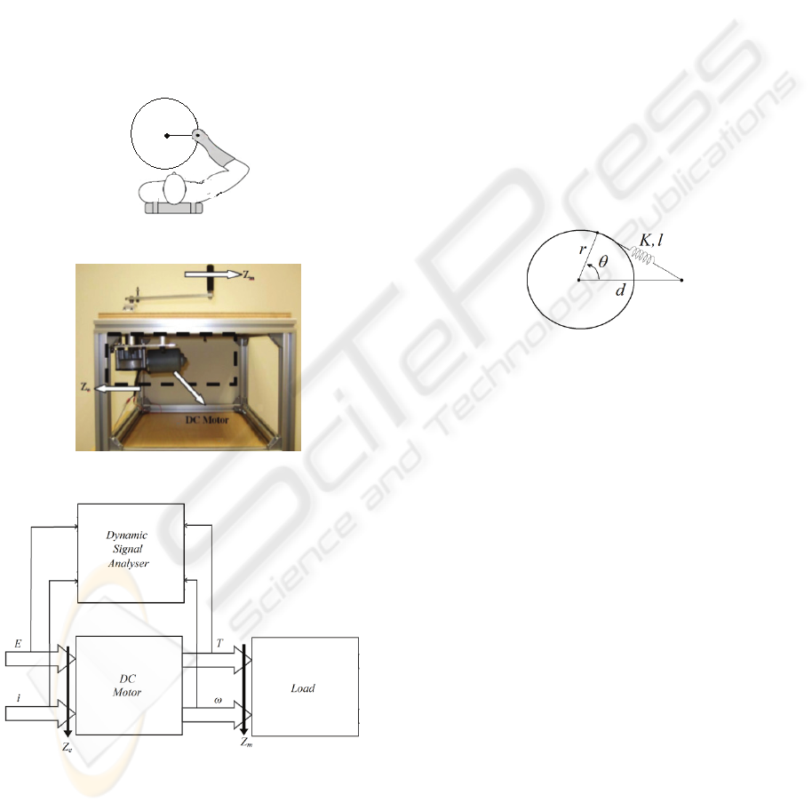
A typical shoulder wheel, shown in Figure 2, is
widely known as a common rehabilitation device.
Shoulder wheels are simply found in the market for
inexpensive prices and can be installed and used
easily. Therefore, prescription of such equipment is
welcomed by patients who need physical exercises
on their upper limb. These patients normally suffer
from muscle atrophy and/or a loss in their ranges of
motion. Their practice with a shoulder wheel
involves rotating the shoulder wheel while the
physiotherapist can adjust the radius of the circular
motion. Sometimes they attach some mass blocks to
the wheel such that the patient has to apply more
torque to rotate and control the wheel. Through the
exercise, patients adapt to the motion and their
A NOVEL DEVICE FOR MEASURING MECHANICAL IMPEDANCE DURING DYNAMIC TASKS
65
control over the muscles would improve; hence they
recover.
3.1 Apparatus Design
Here, we use a shoulder wheel equipped with a DC
motor as the measurement apparatus, shown in
Figure 3. The set also involves a current and a
voltage probe, and a dynamic signal analyzer, which
is depicted in Figure 4.
The set-up was used for measuring human arm’s
mechanical impedance while the subject was
exercising with the shoulder wheel, illustrated in
Figure 2.
Figure 2: Subject exercising with the wheel.
Figure 3: A photograph of the experimental set-up.
Figure 4: The SSA system in diagram.
Using the apparatuses we have designed, we can
measure mechanical impedance of the arm
accurately during motion. Study of human motor
learning will then be possible; with designing
appropriate experiments, we can examine a number
of issues in neuroscience i.e. learning, consolidation,
motor forgetting, retention and transfer of tasks. The
quantification of motor function provides a very
good tool for science and many other applications
such as robotics, physical medicine, and
physiotherapy.
3.2 Method Verification
To validate the method, before measuring human
arm’s mechanical impedance, we challenged our
method by attaching a linear spring according to
Figure 5. The elongation force of the spring
generates mechanical impedance that can be
measured and compared to an analytical prediction.
If the two quantities are comparable, the method is
confirmed to be correct. Then we can apply the
method to direct measurement of human arm’s
mechanical impedance.
Figure 5: Shoulder wheel with the eccentric spring.
The moment about at the centre, O, caused by the
spring generates the mechanical impedance at the
rotating wheel. Based on conventional mathematical
and mechanical calculations, we can predict the
mechanical impedance of the wheel.
All constant values such as r, d, and l are measured
from the experimental setup. Spring stiffness, K is
obtained by adding mass, measuring displacement of
the spring and then using least square fitting. The
stiffness was found to be 155.50 N/m.
Moreover, based on transduction matrix theory,
mechanical impedance was measured in an
experiment where the spring is attached to the
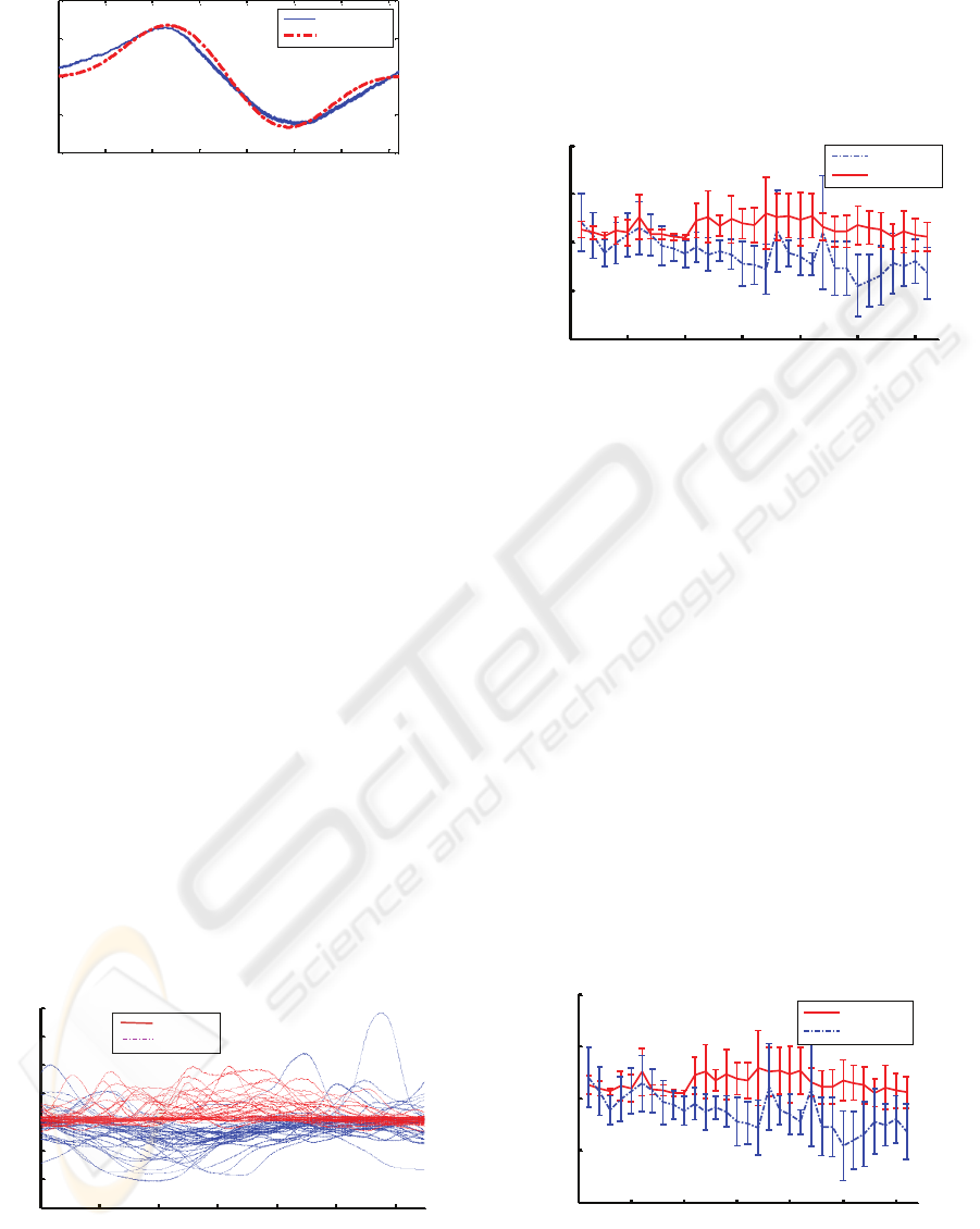
shoulder wheel. In Figure 6, the theoretical data and
the experimental data can be compared. We can see
that they have a very obvious similarity.
As it is observable in Figure 6, there is a good
agreement between the measured value and the
analytical solution. This supports and validates the
accuracy of the measurement method. Now the
method is prepared to use for direct measurement of
the human arm’s mechanical impedance.
BIODEVICES 2010 - International Conference on Biomedical Electronics and Devices
66
0 50 100 150 200 250 300 350
-0.04
-0.02
0
0.02
0.04
θ
(degree)
Z
m
(N.m.s)
Experiment
Theory
Figure 6: Experimental result (solid blue) of the
mechanical impedance of a spring as compared to the
theoretical solution (dashed red).
3.3 Arm’s Impedance
While performing the one-dimensional rotary task
with constant speed, the subjects change their arm’s
mechanical impedance on the wheel to synchronize
their arm’s movement with the rotation. Figure 7 to
Figure 10 show the measurement results of the same
experiment on two right-handed healthy subjects, a
man and a woman both of which do the task with
their right hand.
For both subjects, we observed the adaptation
process in form of changes in mean cycle of the
mechanical impedance, as well as ∆T and ∆ω.
Where ∆ω is the value of ω minus ω0 which is the
angular velocity measured at unloaded condition.
Figure 7 shows arm mechanical impedance of the
two subjects where each performed the task 31
times. Curves in solid line are those of subject 1
while measurements on subject 2 are shown in
dashed lines. We can see that density of the data is
more near the axis Zm=0. This can be explained by
the nature of the task that the subject is asked to
follow the motion without resistance or assistance
which means the velocity of the subject’s hand
should be equal to that of the wheel. Should any
discrepancy occurs, it is considered an error that is
represented in terms of excessive mechanical
impedance.
0 0.2 0.4 0.6 0.8 1 1.2
-0.3
-0.2
-0.1
0
0.1
0.2
0.3
0.4
Time (sec)
Z
m
(N.m.s)
Subject 1
Subject 2
Figure 7: Arm mechanical impedance of two subjects;
each subject performed the trial 31 times. Curves in solid
line are those of subject 1 while measurements on subject
2 are shown in dashed lines.
In order to have a better understanding of how
mechanical impedance changes during adaptation,
mean value of the impedance curves are shown in
Figure 8; in the graphs the error-bar represents the
standard deviation of the impedance in each cycle.
0 5 10 15 20 25 30
-0.2
-0.1
0
0.1
0.2
Number of trials
Mean(Z
m
) (N.m.s)
Subject 2
Subject 1
Figure 8: Mean value of arm mechanical impedance of
two subjects doing 31 trials. Curves in solid line are those
of subject 1 while measurements on subject 2 are shown in
dashed lines.
Please note that the relatively high standard
deviation is mainly because of the stochastic
temperament of the biomechanical system.
Mechanical impedance is a product of T divided by
ω thus an intrinsic property of a mechanical system.
However in this biomechanical system, this property
changes with neural signals. For example, when the
neural signal is low density, the muscles are less stiff
hence we expect that the impedance is lower
comparing to a posture with high density neural
signals. The value of ∆T measured in our experiment
is proportional to the interaction force between the
subject’s hand and the wheel’s handle. The
interaction force, in turn, has to do with each single
muscle’s force. So if we study the changes of the
measured mechanical impedance, we will have some
clue about how neural signals of the muscles
regulated to control the motion of the arm.
0 5 10 15 20 25 30
-1
-0.5
0
0.5
1
Number of trials
Mean(
Δ
T) (Rad/s)
Subject 1
Subject 2
Figure 9: Mean value of the interaction torque of two
subjects in 31 trials. Curves in solid line are those of
subject 1 while measurements on subject 2 are shown in
dashed lines.
A NOVEL DEVICE FOR MEASURING MECHANICAL IMPEDANCE DURING DYNAMIC TASKS
67
Mean value and standard deviation of the torque,
∆T, is shown in form of an error-bar graph in Figure
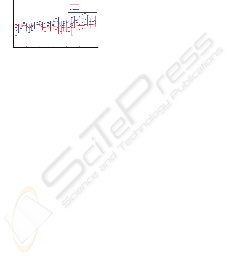
9. In Figure 10 also, we can see the error-bar graph
of mean value and standard deviation of ∆ω.
0 5 10 15 20 25 30
-0.9
-0.8
-0.7
-0.6
-0.5
Number of trials
Mean(
Δω
) (Rad/s)
Subject 1
Subject 2
Figure 10: Mean value of hand velocity of two subjects in
31 trials. Curves in solid line are those of subject 1 while
measurements on subject 2 are shown in dashed lines.
4 AN IMPEDANCE BASED
INDICATOR
In this paper we used an electromechanical
simultaneous sensor cum actuator to propose a
method and a device which is capable of the
measuring impedance, the torque, and the velocity
during motion. In comparison with existing
methods, this methodology is much simpler to use.
More importantly, we can measure the impedance,
the torque, and the angular velocity during any
motion profile accurately. In conventional methods
of impedance measurement, one needs to apply
perturbation while our method does not require
perturbation in a sense of an externally applied
force. In our experiments, we applied a constant
speed to the subject’s limb while their actual
reaching speed profile is always a bell-shape
function. Then we measured impedance based on the
resulted interaction force and the changes in the
initial speed.
The experimental results showed that during
adaptation to a rotational motion with constant
speed, subjects adapted their arm’s mechanical
impedance with changing their interaction force and
velocity.
The tests will be soon available to some stroke
patients before, during, and after upper limb
rehabilitation. The values of impedance, torque, and
velocity will be analyzed and compared to Fugle-
Mayer motor function assessment test in order to
give the evaluators a quantifying tool to help them
with an objective assessment.
ACKNOWLEDGEMENTS
Hereby we would like to acknowledge the School of
Mechanical and Aerospace Engineering at Nanyang
Technological University and the M&C Lab in
especial. We shall also thank Professor Etienne
Burdet for his comments. Last but not least Mrs.
Maryam Khademi’s help with reviewing the paper is
appreciated.
REFERENCES
Burdet E, Osu R, Franklin DW, Milner TE, Kawato M,
2001. The CNS Skillfully Stabilizes Unstable
Dynamics by Learning Optimal Impedance. Nature,
414: 446-9
Darainy M., Ostry D., 2008. Muscle cocontraction
following dynamics learning. Exp Brain Res
190:153–163
Fugl-Meyer AR, Jääskö L, Leyman I, Olsson S, Steglind
S., 1975. The post-stroke hemiplegic patient. 1. a
method for evaluation of physical performance.
Scandinavian Journal of Rehabilitation Medicine.
7(1):13-31
Goldstein LB, Bertels C, and Davis JN, 1989. Interrater
reliability of the NIH stroke scale. Archive of
Neurology, Vol. 46 No. 6
Hogan N., 1984. Adaptive Control of Mechanical
Impedance by Coactivation of Antagonist Muscles.
IEEE Transaction on Automatic Control, vol. AC-29,
no. 8, August
Ling, S-F, Y. Xie, 2001. Detecting mechanical impedance
of structures using the sensing capability of a
Piezoceramic Inertial Actuator. Sensors and Actuators
A: Phys 93: 243-249
Ling S-F, Fu L, 2004. Apparatus for Sensor-less
Monitoring and Diagnosis of Motor Driven
Mechanical Systems. US Patent pending, No.
60/551336, through NTU, 1 March
Ling S-F, Fu L, Tseng CH, 2006. On-line breakage
monitoring of small drills with input impedance of
driving motor. Mechanical Systems & Signal
Processing, 21, 457-465
Loureiro R, Amirabdollahian F, Topping M, Driessen B
and Harwin W, 2003. Upper Limb Robot Mediated
Stroke Therapy—GENTLE/s Approach. Journal of
Autonomous Robots, Volume 15, Number 1
Mousavi Hondori H., Ling S-F, 2009. A Method for
Measuring Human Arm’s Mechanical Impedance for
Assessment of Motor Rehabilitation. 3rdInternation
Convention on Rehabilitation and Assisstance
Technology, i-CREATe
Palazzolo JJ, Ferraro M, Krebs HI, Lynch D, Volpe BT,
and Hogan N, 2007. Stochastic Estimation of Arm
Mechanical Impedance During Robotic Stroke
Rehabilitation. IEEE Transaction on Neural System
and Rehabilitation Engineering, vol. 15, no. 1
BIODEVICES 2010 - International Conference on Biomedical Electronics and Devices
68
