
ADVANCED COMPUTER MODELING FOR INTERSTITIAL
MICROWAVE HYPERTHERMIA THERAPY
Comparison of Two Numerical Methods in Computational Electromagnetics
M. F. J. Cepeda, A. Vera, L. Leija
Dpto. de Ingeniería Eléctrica, Sección Bioelectrónica, CINVESTAV-IPN, San Pedro Zacatenco, México D.F., México
E. Ávila-Navarro
Dpto. de Ciencia de Materiales, Óptica y Tecnología Electrónica. Universidad Miguel Hernández, Elche, Spain
C. Reig, E. A. Navarro
Dpto. de Ingeniería Electrónica, Universitat de València, Burjassot, Spain
Keywords: Hyperthermia, Modelling, Applicator, Cancer.
Abstract: Microwave hyperthermia therapy is a recent development in the field of tumor ablation. Eelectromagnetic
microwave irradiation applied to the tumor tissue causes water molecules to vibrate and rotate, resulting in
tissue heating and subsequently cell death via thermal-induced protein denaturation. To effectively treat
deep-stead tumors, the interstitial antennas should produce a highly localized specific absorption rate pattern
and be efficient radiators at different generator frequencies. Numerical electromagnetic and thermal
simulations are used to optimize the antenna design and predict heating patterns. An advanced computer
modeling of a double slot antenna for interstitial hyperthermia was designed using two different numerical
methods, the Finite Element Method and a Finite-difference time-domain. The aim of this work is to
compare and analyze both numerical methods.
1 INTRODUCTION
1.1 Hyperthermia
Hyperthermia is a type of cancer treatment in which
body tissue is exposed to high temperatures. In
oncology therapeutic treatments, the cancerous cells
can be destroyed if a controlled heating is induced
with temperatures from 6ºC to 8ºC, with minimal
injury to normal tissues. Some clinical trials have
studied hyperthermia in combination with radiation
therapy and/or chemo-therapy. These studies have
focused on the treatment of many types of cancer as
sarcoma, melanoma, and cancers of the head and
neck, brain, lung, oesophagus, breast, bladder,
rectum, liver, appendix, cervix, and peritoneal
lining. These studies have shown a significant
reduction in tumour size when hyperthermia is
combined with other treatments.
1.2 Methods of Hyperthermia
Several methods of hyperthermia are currently under
study, including local, regional, and whole-body
hyperthermia.
1) Local hyperthermia is used to heat a small area,
such as a tumor. It involves creating very high
temperatures that destroy the cells that are heated.
Radio waves, microwaves, ultrasound waves, or
other forms of energy can be used to heat the area.
2) In regional hyperthermia, various approaches
may be used to heat large areas of tissue, such as a
body cavity, organ, or limb.
3) Whole-body hyperthermia is used to treat
metastatic cancer that has spread throughout the
body. This can be accomplished by several
techniques that raise the body temperature, including
the use of thermal chambers or hot water blankets.
166
Cepeda M., Vera A., Leija L., Ávila-Navarro E., Reig C. and Navarro E. (2010).
ADVANCED COMPUTER MODELING FOR INTERSTITIAL MICROWAVE HYPERTHERMIA THERAPY - Comparison of Two Numerical Methods in
Computational Electromagnetics.
In Proceedings of the Third International Conference on Biomedical Electronics and Devices, pages 166-169
DOI: 10.5220/0002711501660169
Copyright
c
SciTePress

1.3 Interstitial Hyperthermia
This technique allows the tumor to be heated to
higher temperatures than external techniques. Under
anesthesia, probes or needles are inserted into the
tumor. The heat source is then inserted into the
probe. For the treatment of superficial tumors the
radiation is applied through external antennas, while
internal tumors are exposed to invasive applicators.
The operating frequency is usually 2.450 GHz,
which is one of the ISM (Industrial, Scientific, and
Medical) dedicated frequencies. These techniques
employ implanted minimally invasive thin antennas
for the delivery of local thermal doses; they are
inserted through the skin, into a biocompatible
catheter, under the guidance provided with an
imaging monitoring procedure (Ito, 2002).
1.4 Numerical Methods
Three main techniques exist within computational
electromagnetics (CEM). The first of these, the
finite-difference time-domain (FDTD) (Yee, 1966)
uses finite difference approximations of the time and
space derivatives of Maxwell's curl. This method has
been widely used to numerically evaluate the
electromagnetic radiation patterns of antennas in
tissue (Sullivan, 1990). The method of moments
(MoM), approximates numerical solutions to
integral equations, formulated in the frequency
domain to determine an unknown current
distribution for an antenna. The finite element
method (FEM), has been extensively used in
simulations of cardiac and hepatic radiofrequency
(RF) ablation (Haemmerich, 2003). FEM models
can provide users with quick, accurate solutions to
multiple systems of differential equations and as
such, are well suited to heat transfer problems like
ablation (Bertram, 2006).
2 MATERIALS AND METHODS
2.1 Governing Equations
The frequency-dependent reflection coefficient and
specific absorption rate (SAR) pattern in tissue are
important for the performance of interstitial
antennas. The frequency-dependent reflection
coefficient, can be expressed as:
Γ f
()
= 10 ⋅ log
10
P
r
f
()
P
in
⎛
⎝
⎜
⎞
⎠
⎟
dB
[]
(1)
where P
in
is the input power and P
r
indicates
reflected power (W). The frequency where the
reflection coefficient is minimum is commonly
referred to as the resonant frequency and should be
approximately the same as the operating frequency
of the generator used. SAR represents the amount of
time average power deposited per unit mass of tissue
(W/Kg) at any position. It can be expressed
mathematically as
SAR =
σ
2
ρ
v
E
2
W / kg
[]
(2)
where σ is tissue conductivity (S/m), ρ is tissue
density (kg/m
3
) and E is the electric field vector
[V/m]. The tissue temperature increase results from
both power and time, caused by direct MW heating
(from SAR) and tissue thermal conduction. MW
heating thermal effects can be roughly described by
Pennes’ Bioheat equation (Pennes, 1948):
∇⋅ −k∇T
(
)
=
ρ
b
C
b
ω
b
(T
b
− T ) + Q
met
+ Q
ext
(3)
where k is the tissue thermal conductivity (W/m°K),
ρ
b
is the blood density (Kg/m
3
), C
b
is the blood
specific heat (J/Kg°K), ω
b
is the blood perfusion rate
(1/s). T
b
is the temperature of the blood and T is the
final temperature. Q
met
is the heat source from
metabolism and Q
ext
an external heat source.
2.2 Material Properties
The antenna is based on a 50Ω UT-085 semirigid
coaxial cable. The outer conductor is copper, in
which a two small ring slot of width is cut close to
the short-circuited distal tip of the antenna to allow
electromagnetic wave propagation into the tissue.
The inner conductor is made from silver-plated
copper wire (SPCW) and the coaxial dielectric used
is a low-loss polytetrafluoroethylene (PTFE).
Furthermore the antenna is encased in a PTFE
catheter to prevent adhesion of the probe to
desiccated ablated tissue. Characteristics of the
materials and tissue are listed in Tab. 1.
2.3 Applicator Design
Antenna geometry parameters were chosen based on
the effective wavelength in muscle at 2.45 GHz,
which was calculated using the equation:
[]
m
f
c
r
eff
ε
λ
=
(4)
where c is the speed of light in free space (m/s), f is
the operating frequency (2.45 GHz), and ε
r
= 52.729
ADVANCED COMPUTER MODELING FOR INTERSTITIAL MICROWAVE HYPERTHERMIA THERAPY -
Comparison of Two Numerical Methods in Computational Electromagnetics
167
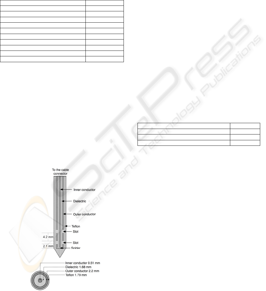
is the relative permittivity of the tissue at the
operating frequency. Fig. 1 shows that the slot
spacing length corresponds to 0.25 λ
eff
, and 0.0125
λ
eff
respectively, that was chose to achieve localized
power deposition near the slots of the antenna.
Table 1: Dimensions and material properties for the
materials and tissue.
Parameter Value
Center conductor diameter 0.51 mm
Dielectric diameter 1.68 mm
Outer conductor diameter 2.2 mm
Diameter of catheter 1.79 mm
Tissue electrical conductivity 1.7388 S/m
Tissue thermal conductivity 0.5 W/m°K
Material ε
r
Inner dielectric of the coaxial cable 2.03
Catheter 2.60
Tissue 52.729
2.4 Computer Model Definition
2.4.1 Finite Element Method
Effects are modeled using commercial software
package (COMSOL Multiphysics ™). The FEM
model assumes that the coaxial slot antenna is
immersed in homogeneous tissue. Fig. 1 shows the
axial schematics of each section of the antenna, and
the interior diameters. The inner and outer
conductors of the antenna were modeled using
perfect electric conductor boundary conditions and
boundaries along the z axis are set with axial
symmetry.
Figure 1: Shows the axial schematics of each section of
the antenna, and the interior diameters.
2.4.2 Finite-Difference Time-Domain
The code was originally designed for the simulation
of especially printed antennas (Ávila-Navarro, 2006)
and recently adapted for material with losses. This is
an algorithm in 3D Cartesian coordinates and full-
wave in order to obtain electromagnetic fields in the
time domain at any point in the simulated structure.
The mesh used for the spatial discretization of the
problem is configurable. By applying the Fast
Fourier Transform (FFT) the field distributions is
calculated in any plane, and therefore the SAR is
obtained.
3 RESULTS
3.1 Finite Element Method
The mesh size was generated using the mesh
parameters in Table 2. The mesh consists of 3655
triangular elements. Dense mesh zone has been
generated in the vicinity of the tip of the antenna,
where the temperature is more concentrated.
Table 2: Mesh parameters.
Maximum element size scaling factor 0.55
Element growth rate 1.25
Mesh curvature factor 0.25
Mesh curvature cutoff 0.0005
Fig. 2 shows the heat source density. The
axisymmetric model requires 220 MB memory and
11 s of CPU time for single simulation on a Intel 2.4
GHz Core 2 Duo processor and a MAC OS X
v10.5.7 operative system.
3.2 Finite-Difference Time-Domain
The simulated reflection coefficient expressed
logarithmically of the coaxial double slot antenna at
2.45 GHz was -20.04. The total number of cells is
approximately 587,000. The applicator is immersed
in a homogeneous region simulating the human
tissue. Fig. 3 shows the SAR obtained with the
FDTD code for the coaxial double slot applicator
used. The reflection coefficient calculated for the
frequency of 2.45GHz is -11.2dB.
3.3 Model Validation
To validate the performance of computer model, a
double slot antenna was constructed from UT-85
semirigid coaxial cable and a SMB connector. Fig. 4
shows the temperature distribution in a Cholesteric
BIODEVICES 2010 - International Conference on Biomedical Electronics and Devices
168
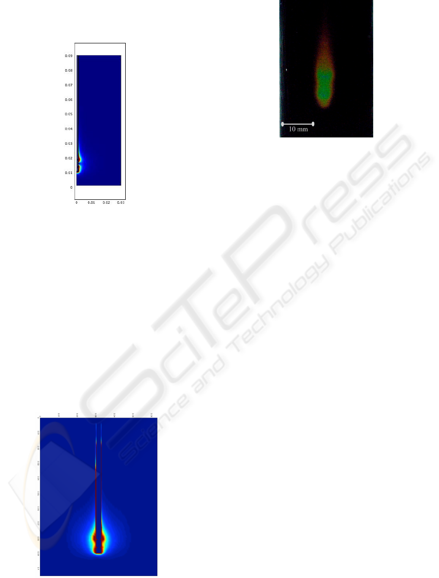
Liquid Crystals (LCR, model NPR30C5B) at 1 W.
The temperature measurement experiment setup is
described in (Cepeda – 2008).
Figure 2: The computed microwave heat source density.
4 CONCLUSIONS
We have developed two models in parallel of an
applicator for microwave hyperthermia therapy. The
first of these was using commercial software based
on FEM. For the other a specific code based on
FDTD has been developed. Nevertheless both results
are comparable. The potency of the first and
versatility of the second method allows
complementing and improving the design for a
future application. Finally, there is an increasing
need to design and evaluate applicators, which
permit to improve antennas for interstitial
hyperthermia using the Penne’s bioheat equation.
Figure 3: SAR distribution produced by FDTD.
Figure 4: A picture of the hyperthermia experiment.
Shows the color changes with the rise in temperature.
REFERENCES
K. Ito, K. Saito, T. Taniguchi, H. Yoshimura, 2002.
Temperature distribution in and around array
applicator for interstitial microwave hyperthermia
combined with interstitial radiation therapy," Proc.
27th Intl. URSI Gen. Assembly, Maastricht.
Yee KS., 1966. Numerical solution of initial boundary
value problems involving Maxwell's equations in
isotropic media. IEEE Trans Ant Prop, AP-14:302-
307.
Sullivan D., 1990. Three-dimensional computer
simulation in deep regional hyperthermia using the
finite-difference timedomain method. IEEE Trans
Microw Theory Tech., 38:204-211.
Haemmerich D, Chachati L, Wright AS, Mahvi DM, Lee
FT, Webster JG., 2003. Hepatic radiofrequency
ablation with internally cooled probes: Effect of
coolant temperature on lesion size. IEEE Trans
Biomed Eng., 50:493-500.
John M Bertram, Deshan Yang, Mark C Converse, John G
Webster and David M Mahvi, 2006. Antenna design
for microwave hepatic ablation using an axisymmetric
electromagnetic model BioMedical Engineering
OnLine. Biomed Eng Online 5: 15.
Wissler EH. Pennes’. 1948. Paper revisited. J Appl
Physiol 1998;85(1):35–41.
E. Ávila-Navarro, J.M. Blanes, J.A. Carrasco, C. Reig,
E.A. Navarro, 2006. A new bi-faced log-periodic
printed antenna, Microwave and Optical Technology
Letters, vol. 48, No. 2, pp. 402-405.
Cepeda M: F: J, Vera A and Leija L., Microcoaxial
Double Slot Antenna for Insterstitial Hyperthermia:
Modeling and Validation”, International Conference
on Advances in Electronics and Micro-Electronics
ENICS 2008, Valencia, Spain, September, 2008, 138-
143pp. ISBN: 978-0-7695-3370-4
ADVANCED COMPUTER MODELING FOR INTERSTITIAL MICROWAVE HYPERTHERMIA THERAPY -
Comparison of Two Numerical Methods in Computational Electromagnetics
169
