
SIMPLY FABRICATED PRECISE MICROFLUIDIC MIXER
WITH RESIST FLOW PATHS SEALED BY AN ACRYLIC LID
Toshiyuki Horiuchi, Hiroyuki Watanabe
1
, Naoki Hayashi
2
and Takuya Kitamura
3
1
Toshiba Mobile Display, Co., Ltd.,
2
CANON Inc.,
3
Nagano Electronics Industrial Co., Ltd.
Precision Engineering, Tokyo Denki University, 2-2, Kanda-Nishiki-Cho, Chiyoda-Ku, Tokyo, Japan
Keywords: Microfluidic mixer, Microfluidic device, Thick resist, Flow path, Aspect ratio.
Abstract: A microfluidic mixer was simply and easily fabricated using 380-μm thick patterns of negative resist SU-8
as flow paths and sealing the paths by an acrylic lid plate. The SU-8 was mainly composed of epoxy resin,
and it was hardened by the baking after the development. Because the too narrow flow paths were not
practical, the target width of the flow-path was set at 30-100 μm. The aspect ratio limit for 1:1 line-and-
space patterns increased when the pattern width became large and the lower numerical-aperture or higher F-
number projection lens was adopted. The maximum aspect ratio for line-and-space patterns with a width of
26-53 μm was 6.5-8, corresponding to the pattern width and the numerical aperture. After snail-shape flow-
path groove patterns were successfully fabricated, the resist block was covered by an acrylic lid plate and
sealed using screws. After microtubes were attached to the entrance and exit holes, red and blue colored
waters were injected into the two entrance tubes. As a result, two waters were mixed while passing through
the snail-shape paths, and dark purple water was ejected from the exit. It was successfully verified that the
easily and simply fabricated microfluidic mixer actually worked well.
1 INTRODUCTION
Among a lot of biodevices, microfluidic reactor,
mixer and other modules used for sensing and
analyzing are the most important and useful devices.
For this reason, various fabrication methods of
microfluidic devices are proposed. For example, fine
grooves are mechanically cut on the surfaces of
slide-glasses or quartz plates. Glassy materials are
chemically stable and not reactive. Accordingly,
they are suitable for the materials to fabricate
chemical-use devices. However, because the glassy
materials are fragile, it is difficult to make dense and
deep grooves. Moreover, it takes a long time to
machine the materials.
In most cases, microfluidic devices mentioned above
are thrown away after once they are used.
Accordingly, they should be easily fabricated with a
low cost. For this reason, various fabrication
methods using the technologies for applying to
Micro Electro Mechanical Systems (MEMS) are
developed. Most of MEMS microfluidic devices
directly use the resists such as poly-dimethyl-
siloxane (PDMS) (Lien, 2008) (Lei, 2008)
(Casquillas, 2008), SU-8 (Tsai, 2006) (Yang, 2007)
and poly-methyl-methacrylate (PMMA) (Nugen,
2009) as flow paths. Some of the proposed devices
used the combination of the plural resists (Kontakis,
2009) (Lo, 2008) (Ho, 2008).
On the other hand, similar flow paths are also
formed by etching silicon or glass substrates using
the resist patterns printed by lithography as the
etching masks (Avram, 2008) (Eun, 2008).
However, because most of the proposed methods
require complicated long processes, high fabrication
costs are anticipated. For this reason, a simple and
easy but highly accurate and useful fabrication
method of microfluidic devices is investigated here.
Dense and deep microfluidic patterns are printed
using thick SU-8 resist films mainly composed of
epoxy resin. It is not difficult to print high-aspect
patterns if the appropriate projection exposure
conditions are selected. Therefore, good flow paths
are fabricated by a simple lithography process. Once
the resist is sufficiently baked, it is hardened and
works like normal plastics. Accordingly, the baked
resist patterns are effectively used as flow paths of
throw-away microfluidic devices.
In this paper, investigation on the thick resist
patterning process is shown, and the aspect ratio
82
Horiuchi T., Watanabe H., Hayashi N. and Kitamura T. (2010).
SIMPLY FABRICATED PRECISE MICROFLUIDIC MIXER WITH RESIST FLOW PATHS SEALED BY AN ACRYLIC LID.
In Proceedings of the Third International Conference on Biomedical Electronics and Devices, pages 82-87
DOI: 10.5220/0002715100820087
Copyright
c
SciTePress
limit for 1:1 line-and-space patterns is clarified
correlating with the numerical aperture (NA) of the
projection lens. In addition, a precise microfluidic
mixer is actually fabricated. Two colored waters are
successfully mixed using the fabricated device.
2 PATTERNING CONDITIONS
In this research, negative SU-8 100 (MicroChem
Corp.) was used as a resist. Referring to the material
composition description provided by the supplier,
SU-8 is composed of Epoxy Resin of 35-75%,
Gamma Butyrolactone of 20-60%, Mixed
Tryarylsulfonium/Hexafluoroantimonate Salt of
3.5%, and Propylene Carbonate of 1-5%. Patterning
process conditions used in the experiments are
shown in Table 1. The SU-8 was coated on copper-
clad plastic substrates and silicon wafers in
thicknesses between 65-420 nm. Thick films were
obtained by double or triple repetitions of resist
coating and baking.
The copper-clad plastic substrates were used
because various electrode patterns are easily formed,
if necessary. Moreover, metals are directly
electroplated on them for fabricating the injection
molds. On the other hand, silicon wafers were used
to observe the cross sections of patterns by snapping
them along the crystal direction.
Table 1: Patterning conditions of SU-8.
Resist patterns were printed using a handmade
simple exposure system (Hirota, 2003). The
specifications are shown in Table 2. The system uses
a camera lens as a projection lens, and the numerical
aperture or the F-number is controllable.
It was clarified that the maximum aspect ratio
depended on the F-number, and the larger the F-
number was, the higher aspect ratio was obtained.
When the patterns were printed under various F-
number conditions, the highest aspect patterns
shown in Fig. 1 were printed (Horiuchi, 2008).
Table 2: Specifications of the exposure system.
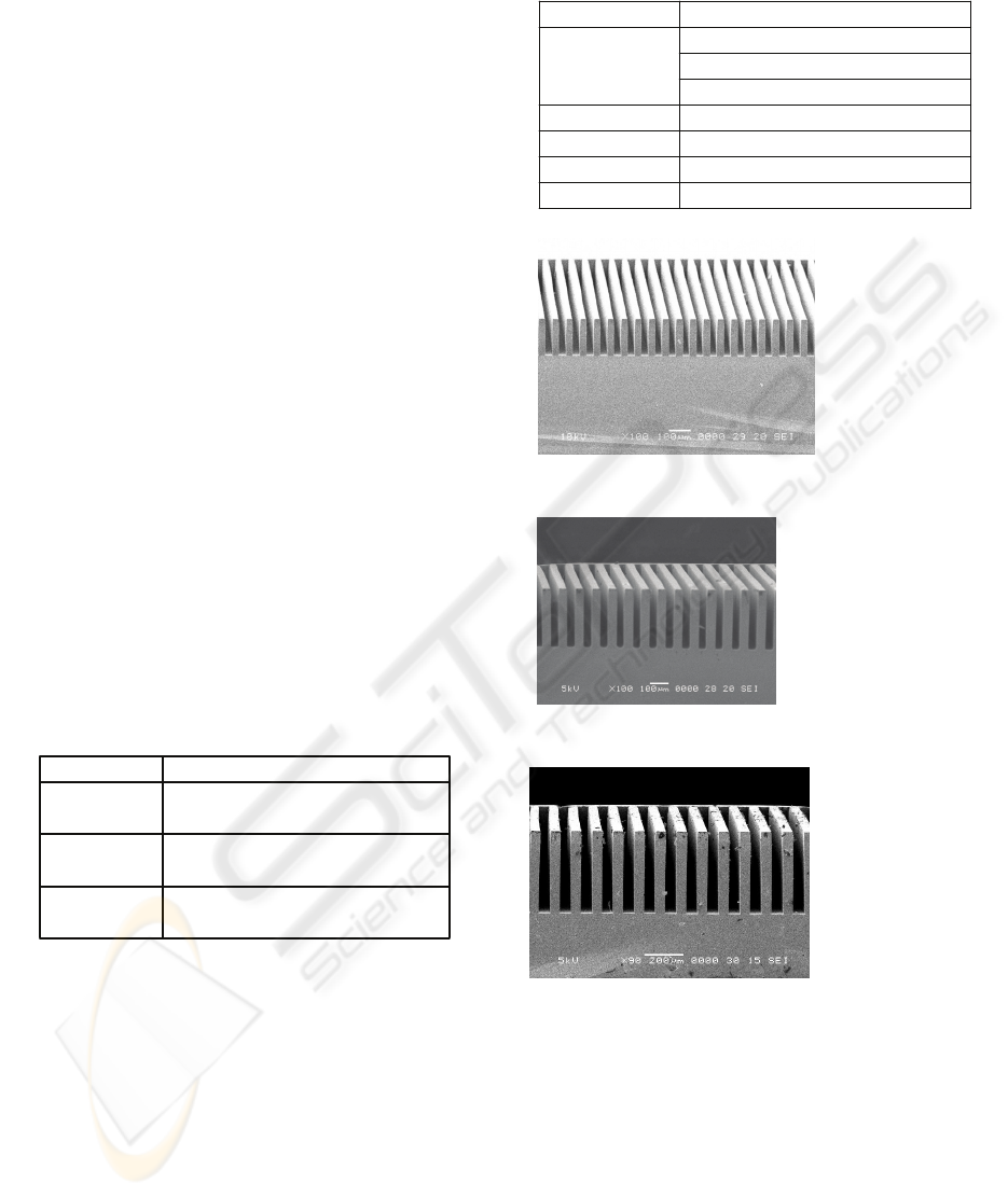
Figure 1: High aspect patterns obtained under various
F-number conditions.
The critical factor deciding the aspect ratio was not
the pattern collapse but the depth-of-focus (DOF) for
securing sufficient image contrast throughout the
resist thickness. The pattern collapse was prevented
by giving sufficient exposure dose, as shown in Fig.
2. The highest aspect ratio for 1:1 line-and-space
patterns became as shown in Fig. 3, and they were
6.5-8.0 for F-numbers of 5.6-11.2,
(c)
F: 11.2
Width: 52.6µm
Thickness: 420 µm
Aspect ratio: 8.0
(b)
F-number: 8
Width: 42.1µm
Thickness: 300 µm
Aspect ratio: 7.1
A little resist remains at
the bottom.
(a)
F-number: 5.6
Width: 31.6µm
Thickness: 170µm
Aspect ratio: 5.4
Wavelength: 290-440 nm
Camera lens (Yashika), F=2.8-16
Ultra-violet lamp, LS-140UV
Reduction ratio
Item
Light source
1/19
2.2 mm square
Projection lens
X and Y: ±6.5 mm, Z: ±5mm
Field size
Specification
(Sumita Optical Glass)
Wafer stage
Process
Pre-bake
Step2: 50 min at 95°C in an oven
1/19 low-NA projection exposure,
Dip in SU-8 developer, 5-40 min
Step1: 20 min at 65°C in an
oven
Exposure
Rinse in 2-propanol, 1-2 min
Development
Condition
4-10 min
SIMPLY FABRICATED PRECISE MICROFLUIDIC MIXER WITH RESIST FLOW PATHS SEALED BY AN
ACRYLIC LID
83
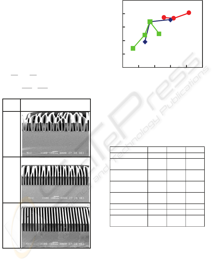
respectively.
Because the high aspect ratio was obtained for the
quite large patterns compared with the critical-size
patterns, the redundancy to print the fluid-path
patterns was considered.
The pattern width w to obtain the highest aspect ratio
experimentally changed as shown in Table 3,
depending on the resolution R and the DOF of the
projection optics. Here, DOF
c
is the DOF for the
patterns with the critical width R, and they were
calculated by equations (1) and (2). The central
wavelength λ was assumed to be 365 nm. NA is the
numerical aperture of the projection lens. The
constants k
1
and k
2
were assumed to be 0.7 and 1.0.
1
0.7 0.7 2 1.4 .Rk F F
NA NA
λλ
λ
λ
== =×=
(1)
2
2
22
4.
c
λλ
DOF k F
NA NA
λ
=== (2)
Figure 2: Pattern collapse prevention by giving a large
exposure dose. F-number is 5.6.
Figure 3: Maximum aspect ratio dependence on resist
thickness and F-number.
From the calculated resolution limit R and the
pattern width w for obtaining the highest aspect
ratio, w/R was also calculated, as shown in Table 3.
The ratio w/R was almost constant without
depending on the F-number.
Table 3: Resolution versus pattern width and thickness for
obtaining the highest aspect ratio.
Although the DOF
c
for the critical size pattern was
calculated above, DOF
w
for the patterns with a
width of above w was far larger. Because the first-
order diffraction light angle from the periodical
patterns with a large width of w is R/w times smaller
than that from the critical-size periodical patterns,
the DOF
w
for the patterns with a width of w is
multiplied by w/R. Therefore, DOF
w
is calculated as
shown in Table 3. It was known that the DOF
w
was
sufficiently deep for printing such high-aspect
Ratio w/R
(Calculated)
F-number
NA
5.6 8 11.2
0.089 0.063 0.045
R (μm)
2.86 4.09 5.72
(Calculated)
DOF
c
(μm)
45.8 93.4 183
w (μm)
26.3 42.1 52.6
(Experimental)
Resist
170 300 420
thickness (μm)
Aspect ratio
6.5 7.1 8.0
DOF
w
(μm)
421 962 1680
(Calculated)
9.2 10.3 9.2
Exposure
time
5 min
7 min
6 min
26-μm line-and-space patterns
(170-μm thick resist)
0
100 200 300 400 500
0
2
4
6
8
10
F=11.2
F=5.6
Resist thickness (μm)
Maximum as
p
ect ratio
F=8
BIODEVICES 2010 - International Conference on Biomedical Electronics and Devices
84
patterns in thick resist films. This performance is
caused by the utilization of the low-NA or large F-
number projection optics.
It was considered that too narrow flow paths were
irrelevant to fabricate practical microfluidic devices.
From the experience, minimum flow-path width for
fluids such as water and alcohol was estimated to be
30-100 μm. For this reason, considering the
resolution redundancy, F-number of 5.6 was selected
to fabricate an actual microfluidic device. Under this
condition, patterns with 26.3-36.8 μm were printed
well with a considerable exposure time margin, as
shown in Fig. 4. Patterning characteristics for wider
line-and-space patterns with a width of 105 μm were
also investigated. Figure 5 shows the results. Nice
patterns were obtained for long exposure time of up
to twice longer than the time for obtaining the
nominal width patterns, and groove patterns much
narrower than the nominal width were obtained for
the long exposure time.
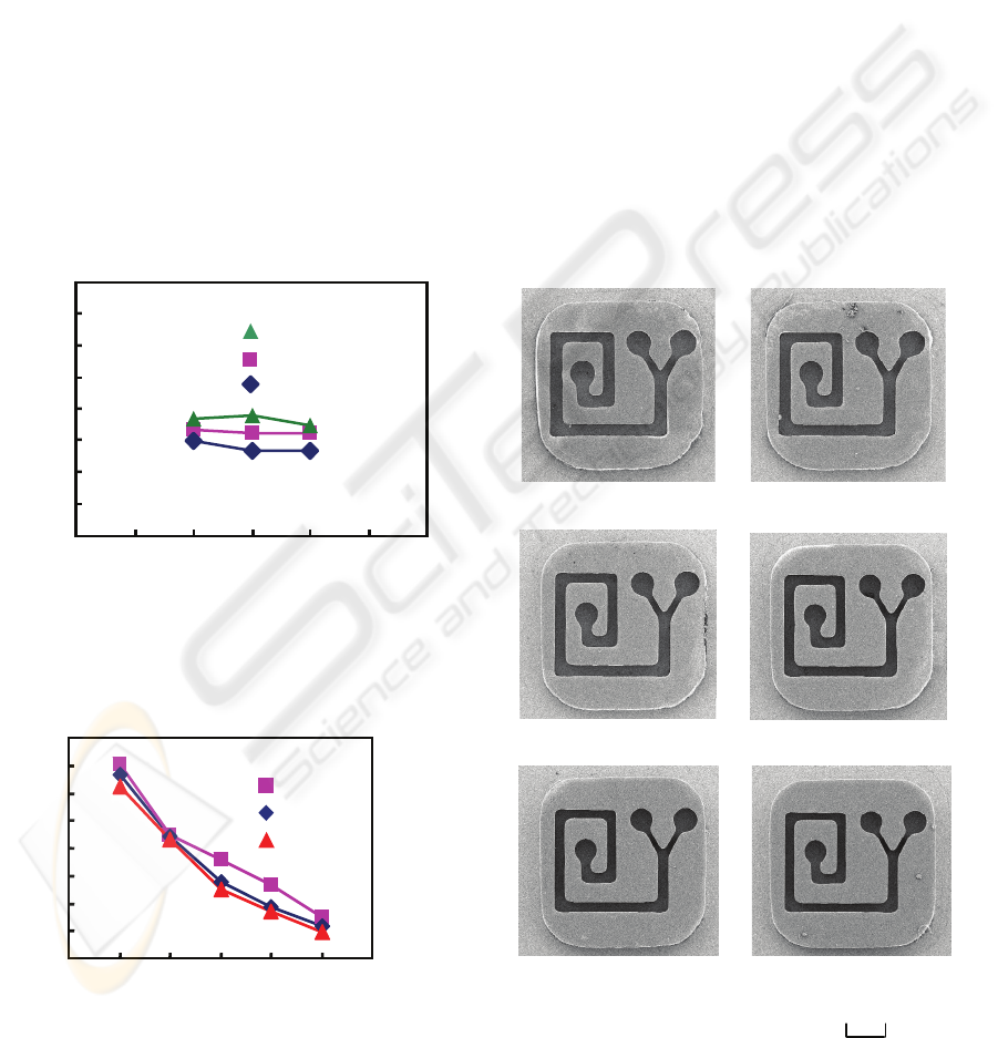
Figure 4: Stable space-pattern-width controllability of
narrow high-aspect patterns.
Resistthickness
100μm
260μm
380μm
Exposuretime(min)
Spacepatternwidth(μm)
40
50
60
70
80
90
10
11
12
3
4
5
67
89
105‐
μmL&S
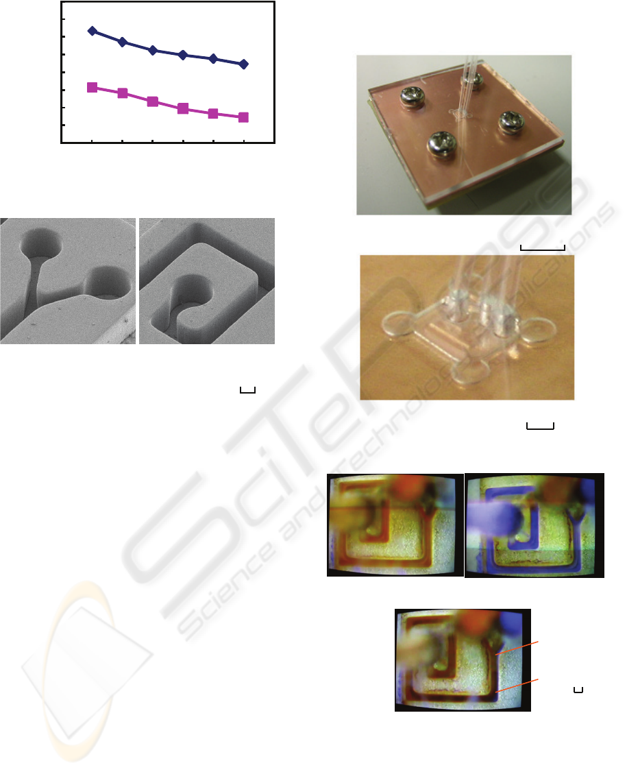
Figure 5: Change of large space pattern width depending
on the exposure time and resist thickness.
3 REPLICATION OF
MICRO-MIXER RESIST
PATTERNS
Considering the results obtained in the previous
chapter, actual microfluidic mixer patterns with a
snail-shape were printed using 380-μm-thick SU-8.
Printed patterns were shown in Fig. 6, and the
groove widths at the Y-shape entrance and the
confluent throat were measured as shown in Fig. 7.
Because the groove-width change became
smallest and the clearest pattern profiles were
obtained, 9 min was the optimum exposure time.
Bird’s eye view of the resist patterns at the entrance
and the exit are shown in Fig. 8. Printed patterns had
vertical and sharp sidewalls. The groove width and
the aspect ratio at the Y-shape entrance were 73μm
and 5.2, respectively, when the exposure time was 9
min. The vertical confluent groove had a width of
135 μm and aspect ratio of 2.8.
500
μ
m
(a) Exposure: 5 min
(b) Exposure: 6 min
(d) Exposure: 8 min
(c) Exposure: 7 min
(f) Exposure: 10min
(e)
Exposure: 9mi
n
Figure 6: Micro-mixer patterns fabricated under various
exposure-dose conditions.
Exposure time (min)
0
10
20
30
40
50
60
70
80
3 4 5 6
7
8 9
31.6-μm L&S
26.3-μm L&S
36.8-μm L&S
Resist thickness: 170 μm
Space pattern width (min)
SIMPLY FABRICATED PRECISE MICROFLUIDIC MIXER WITH RESIST FLOW PATHS SEALED BY AN
ACRYLIC LID
85
Exposuretime(min)
Groovepatternwidth(μm)
4 5
67
8 9
10 11
40
60
80
100
120
140
160
180
200
Confluentpart
Entranceneck
Figure 7: Width variances of micro-reactor patterns.
Figure 8: Entrance and exit patterns of a micro-reactor.
The minimum groove width was 73 μm.
4 ASSEMBLY OF A
MICRO-FLUIDIC MIXER
Using the snail-shape grooves shown in Fig. 6 and 8
as fluid paths, a micro-reactor was fabricated. The
resist grooves were tightly covered by an acrylic lid
plate to make the paths sealed. The lid plate had a
concave with a size a little larger than the outer edge
of the resist block, two entrance holes, and one exit
hole. The plate was machined using a simple
automatic 3-dimensional milling machine (Roland,
PNC-300 CAMM-3). Micro-tubes with an outer and
inner diameters of 500 and 300 μm were inserted
into the three holes and adhered, as shown in Fig. 9.
The tubes were made of poly-fluoro-acrylate (PFA).
Flowing and mixing capability was checked by
injecting colored waters from the two entrances
using syringes. The injected waters were colored red
and blue using watercolors. The colored waters were
successfully mixed while they passed through the
snail-shape paths, as shown in Fig. 10, and the
ejected water had an even dark purple color, that
means the red and blue waters were mixed well. The
waters did not leaked, and the flow paths made of
resist SU-8 were not damaged at all, and it was
verified that the simply and easily fabricated
microfluidic mixer was useful.
Figure 9: Outlook of the fabricated microfluidic mixer.
Figure 10: Successful mixing of two colored waters.
100
μm
(a) Red water injection. (b) Blue water injection.
(c) Injection of Red and blue waters.
A
B
1mm
(b) Main part.
10mm
(a) Total outlook.
(a) Entrance holes (b)Exit hole
100 μm
BIODEVICES 2010 - International Conference on Biomedical Electronics and Devices
86

5 CONSIDERATION
First, advantages and disadvantages of the proposed
microfluidic mixer were considered. Because the
SU-8 patterns are easily printed and they are used as
the flow paths as they are, the fabrication process
was very simple and easy. Although reticles were
needed for projection lithography, very low-cost
film-reticles were applicable without any problems.
In addition, microfluidic mixers are generally used
by themselves, and accurate reticle alignment is not
needed. For this reason, projection exposure systems
may be very simple and plain. Even handmade
exposure systems or photo printers used for printing
off photographs from the negative films are useful.
The proposed microfluidic mixers are applicable
to some micro total analysis systems (μ-TAS). The
tolerances for various body fluids, juices and
chemical reagents have to be investigated hereafter.
The tolerances may not be universal comparing with
those of quartz and glass. However, probably, the
proposed microfluidic mixer will also have good
tolerances for most of the fluids including blood.
Next, fluidic parameters were studied. Although
the colored waters were manually injected using
syringes at the room temperature this time, and the
flow rate was not severely controlled, Reynold’s
number Re=Vd/(μ/ρ) was roughly estimated. It took
less than or equal to 0.1 s to flow the waters through
the device, and the flow path length between the
entrance and the exit was approximately 5.6 mm.
Therefore, the average flow rate V is roughly
calculated to be V=60 mm/s. On the other hand, the
path width d, fluid viscosity μ and the density ρ are
135 μm, ≈1 mPa·s and ≈1 g/cm
3
, respectively.
Therefore, Re is calculated to be ≈8. Accordingly,
the flow is supposed to be a laminar flow. In fact,
the red and blue waters divide the path into halves
between points A and B in Fig. 10(c).
It is not always necessary to make the groove so
deep. However, device sizes can be reduced by
using the deep grooves to secure the same cross
sectional area sizes and allocate the groove closely
each other.
6 CONCLUSIONS
A new method to fabricate microfluidic reactors or
mixers very simply and easily was demonstrated.
Negative SU-8 resist being composed of epoxy resin
with a thickness of 380 μm was used as flow paths.
Because even the 1:1 L&S patterns were printed
with very high aspect ratios of more than 5, deep
flow grooves were easily fabricated. A snail-shape
micro-reactor with a minimum flow-path width of
73 μm was actually fabricated. The resist flow paths
were sealed covering the resist block by an acrylic
lid plate with a concave a little larger than the resist
block and combining the substrate and the lid plate
by screws. Micro tubes were attached to the entrance
and exit holes, and red and blue colored waters were
injected through the micro-tubes using syringes. As
a result, the colored waters were successfully mixed
in a dark purple color, and ejected from the exit tube
without any leaks. The new method and structure for
the microfluidic devices are practical and effective.
ACKNOWLEDGEMENTS
This work was partially supported by Research
Institute for Science and Technology of Tokyo
Denki University Grant Number Q09M-05 in 2009.
REFERENCES
Lien, K. Y., Liu, C.J., Lee, G. B., 2008. MEMS 2008,
IEEE 21
st
International Conference on Micro Electro
Mechanical Systems, 66-69.
Lei, L., Mattos, I. L., Chen, Y., 2008. Microelectronic
Engineering 85, 1318-1320.
Casquillas, G. V., Bertholle, F., Berre, M., Meance, S.,
Malaquin, L., Greffet, J. J., Chen, Y., 2008.
Microelectronic Engineering 85, 1367-1369.
Tsai, N. C., Sue, Sue, C. Y., 2006. Biosensors and
Bioelectronics 22, 313-317.
Yang, R., Soper, S. A., Wang, W., 2007. Sensors and
Actuators A 135, 625-636.
Nugen, S. R., Asiello, P. J., Connelly, J. T., Baeumner, A.
J., 2009. Biosensors and Bioelectronics 24, 2428-
2433.
Kontakis, K., Petropoulos, A., Kaltsas, G., Speliotis, T.,
Gogolides, E., 2009. Microelectronic Engineering 86,
1382-1384.
Lo, C. S., Prewett, P. D., Davies, G. J., Bowen, J., Vanner,
K., 2008, Microelectronic Engineering 85, 1062-1065.
Ho, L. F., Chollet, F., 2008, Microelectronic Engineering
85, 1306-1310.
Avram, M., Iliescu, C., Volmer, M., Avram, A., 2008.
Digest of Papers, Microprocesses and Nanotechnology
2008, 21
st
International Microprocesses and
Nanotechnology Conference , 442-443.
Eun, D. S., Kong, D. Y., Chang, S. J., Yoo, J. H., Hong,
Y. M., Shin, J. K., Lee, J. H., 2008. Digest of Papers,
Microprocesses and Nanotechnology 2008, 21
st
International Microprocesses and Nanotechnology
Conference , 448-449.
Hirota, K., Ozaki, M., Horiuchi, T., 2003. Japanese
Journal of Applied Physics 42, 4031-4036.
Horiuchi, T., Watanabe, H., 2008. Journal of
Photopolymer Science and Technology 21, 77-83.
SIMPLY FABRICATED PRECISE MICROFLUIDIC MIXER WITH RESIST FLOW PATHS SEALED BY AN
ACRYLIC LID
87
