
DEVELOPMENT OF AN INTEGRATED ELECTRICAL
STIMULATION SYSTEM WITH FEEDBACK FOR PHYSICAL
REHABILITATION
E. Durana
1,2
, V. Santos
2
, A. Lopes
3
and F. Vistulo de Abreu
1
1
Department of Physics and
2
Department of Mechanical Engineering, University of Aveiro, 3810-193 Aveiro, Portugal
3
Centro de Medicina e Reabilitação da Região Centro - Rovisco Pais, Quinta da Fonte Quente 3060-908 Tocha, Portugal
Keywords: Electrical stimulation, Rehabilitation, Functional Electric Stimulation (FES), Feedback, Spinal Cord Injury
(SCI), Stroke.
Abstract: In physical rehabilitation, electrical stimulation is widely used as a therapeutic method. However, as it is not
common to find portable devices, capable of integrating information from different sensors, and also with
flexibility in signal generation and triggering. This paper presents an integrated electrostimulation system
that encompasses all those facilities. The system integrates feedback signals coming from an accelerometer
and is capable of adapting electrostimulation depending on motor performance. The device uses a
microcontroller for the waveform generation, and allows controlled waveforms to be produced in response
to signals read from feedback sensors. Besides this high versatility, the principle of the power generation
employed by the device and additional hardware circuitry also provides mechanisms to ensure patient safety
in the unlikely cases of malfunction of the microcontroller. Here we also present an example of application
of the device that uses real time feedback information to control electrical stimulation.
1 INTRODUCTION
The latest technological development in electronic
miniaturization opens new perspectives in the
development of more sophisticated systems
integrating multiple components. Electrical
stimulation (ES) devices for medical rehabilitation
could benefit from these advances. Computational
power has also been made widely accessible, with
the appearance of highly portable inexpensive
computers. ES devices could use evolved
computational models to dynamically control the
electrical stimulation delivered by several
independent channels, responding to multiple
sensors, all working synchronously and according to
patient specific rehabilitation programmes.
Medical rehabilitation uses electric stimulation
intensively (Hennings et al., 2006). Usually, patients
with mobility limitations suffer from muscle
atrophy, which hinders their recovery. Electric
stimulation is an artificial way of inducing motor
movement and to prevent atrophy (Buckley et al.,
1987; Langzam et al., 2006; Durfee, 1999). It can
lead to synergistic gains, as the recovery of some
muscle fibbers allows the recovery of many others.
Indeed, clinicians believe that considerable
functional recoveries can be induced through
exercise (Doucet and Griffin, 2008). One main
problem, however, has always been in how to induce
physiological movements. This can be extremely
relevant as otherwise inadequate reinervation may
be stimulated leading to poor motor functional
recovery (Al-Majed et al., 2000; Franz et al., 2008).
Inducing physiological movements through ES has
been difficult for two main reasons. The first is that
electrical stimulation tends to produce non-
physiological muscle activation. Secondly, most
equipments do not use feedback information to
produce stimulation.
The minimisation of these difficulties motivates
the present work. Here we discuss the development
of a small, light and low power consumption circuit
that provides a closed loop electrical stimulation.
The circuit is capable of acquiring data from sensors
(like accelerometers, force sensors and alike),
communicating with a computer which can respond
through a versatile real time activation of ES stimuli.
User performances are registered and can be used in
later clinical evaluation.
88
Durana E., Santos V., Lopes A. and Vistulo de Abreu F. (2010).
DEVELOPMENT OF AN INTEGRATED ELECTRICAL STIMULATION SYSTEM WITH FEEDBACK FOR PHYSICAL REHABILITATION.
In Proceedings of the Third International Conference on Biomedical Electronics and Devices, pages 88-93
DOI: 10.5220/0002717900880093
Copyright
c
SciTePress
This article will focus on the development of an
ES circuit capable of producing symmetric biphasic
pulsed current stimuli, with real time control over
ES parameters (pulse phase, frequency and current
modulation). The circuit uses a microcontroller
(PIC) to integrate ES with inertial sensors data
acquisition and communication with a computer.
Before discussing the circuit, it is important to
introduce the current terminology used to
characterize electrical pulses in ES devices, and also
to discuss what their impact is in ES therapies. This
is done in the next section.
2 ELECTROTHERAPEUTICAL
REQUIREMENTS
Electrical stimulation is an artificial way to trigger
Action Potentials through the application of rapidly
changing electric fields on excitable tissues.
Transcutaneous Electrical Stimulators are the most
common (Nelson et al., 1999). They apply currents
through the skin to excite peripheral nerves.
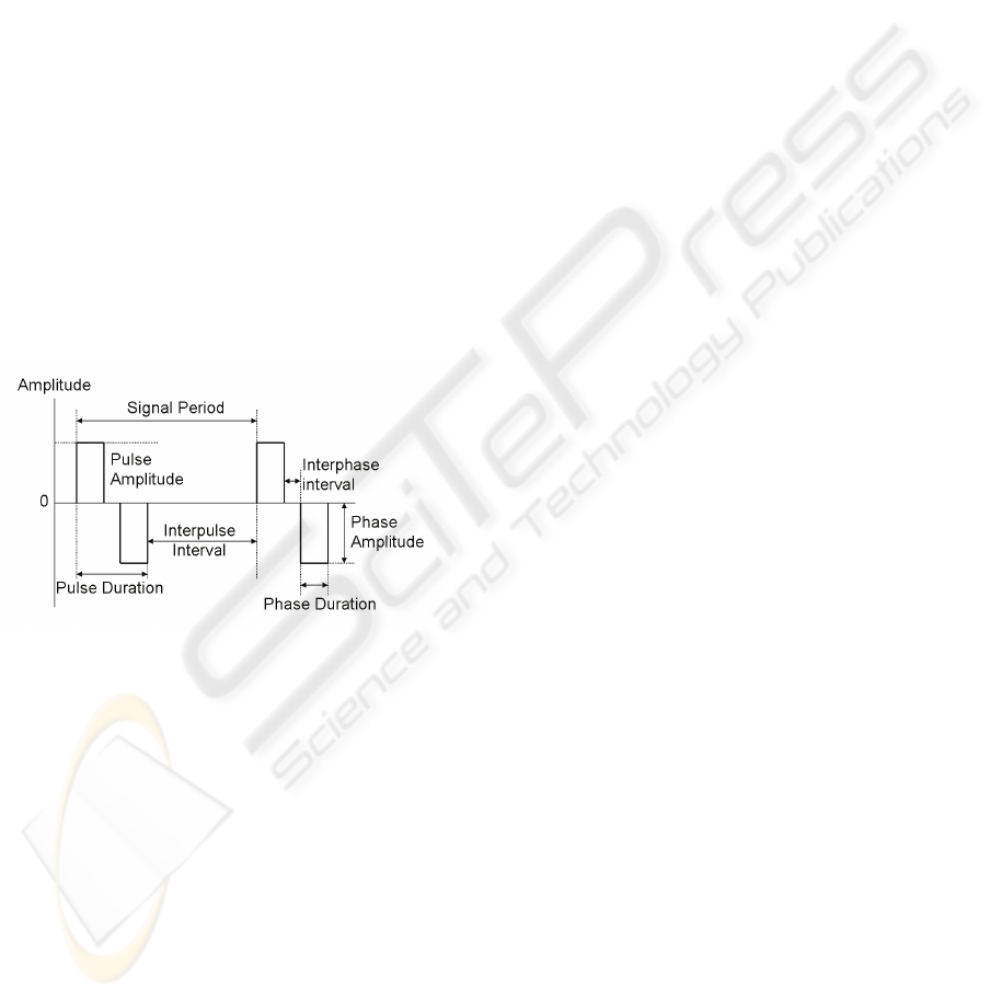
Figure 1: Parameters defining a symmetrical biphasic
pulse.
Pulsed current waveforms are classified in
monophasic or biphasic. In monophasic pulse
signals current flows only in one direction (one
phase) between the electrodes. In biphasic signals
each pulse has two opposing phases. Biphasic pulses
can be symmetric or asymmetric, being symmetric
variants more appropriate for clinical applications
since they leave no residual charges in the
stimulated tissues.
Biphasic pulses are characterised by several
parameters (Figure 1): the pulse amplitude in each
phase, the interphase interval separating each phase,
the interpulse interval and the pulse duration.
Pulsed current signals can be modulated, varying
pulse duration, peak amplitude or pulse rate. This
modulation can be in the form of bursts,
interruptions and ramping. Bursts are created by
trains of pulses that flow for some milliseconds and
then stop for another period of time in a periodic
way. Interrupted pulses are a sequence of pulses
interrupted for a period of time for resting.
Interrupted pulses promote only twitch (brief)
contractions. For higher ES frequencies, bursts fuse
leading to tetanic contractions. In this case the
period between pulses is shorter than the muscle
contraction-relaxation cycle, summating the forces
produced by each impulse (Kitchen, 2002).
The muscle contraction strength can be
augmented by engaging more motor units or by
increasing the frequency at which each motor unit
fires (Vrbová et al, 2008). A higher number of
activated motor units can be achieved by applying
pulses with higher amplitude. The force produced by
increasing the ES frequency depends on the fibre
type. There are two main fibre types in a muscle,
type I and type II. Their proportion varies from
muscle to muscle and depends on function. Fibres
can change their type with exercise, and this is
particularly important in the medical rehabilitation
context. Indeed, in patients without active voluntary
movement, typically they loose type I fibres, a
process that can be reversed and/or prevented by ES.
Type I fibres are slow twitch muscle fibres that
produce relatively low forces but are also the less
fatigable. They are particularly important in
maintaining posture. As a result of their slow
contraction and relaxation they fuse at lower
frequencies when compared with type II fibres. The
later, are responsible for fast movements,
contracting and relaxing faster and consequently
fusing at higher frequencies. It is typically the aim of
the therapist to select the ES programme that best
selects the fibre type to be enhanced.
3 DEVELOPMENT OF AN
INTEGRATED ES DEVICE
The literature on ES circuits is not abundant
although a few examples can be found (Cheng et al.,
2004; McPartland and Mook, 1995). To deliver an
ES stimulus, any ES device has a voltage elevation
stage required to overcome the high skin and other
tissues impedance.
Some methods to increase voltage use
transformers, charge pumps, or switch mode power
supplies. Transformers are costly and large and on
high frequencies, inductive reactance grows
decreasing their efficiency. Charge pumping is
DEVELOPMENT OF AN INTEGRATED ELECTRICAL STIMULATION SYSTEM WITH FEEDBACK FOR
PHYSICAL REHABILITATION
89
another way to step-up voltage with capacitors and
switching elements. There are several charge pump
configurations, like the Cockcroft-Walton voltage
multipliers and the Dickson charge pump (Pan et al.,
2006). The strategy works by charging capacitors in
parallel and then, using switches to rearrange the
circuit, discharge the capacitors now in a serial
configuration.
Switch mode power supply (SMPS) is a power
conversion where high frequency switching is used.
Intrinsic spurious capacitors/inductors in some
electrical components may be used as more effective
means to reduce size and take advantage of their
effects. A particular interesting topology is the
quasi-resonant converter, which has the advantage of
reducing switching losses (Ye et al., 2004;
Pressman, 1998). This is performed by adding a
resonance inductor in series with a switch, a catch
diode and a resonance capacitor, as illustrated in
Figure 2. When the switch is on, the inductor stores
energy in its magnetic field. When the switch is
turned off the stored energy resonates with the
capacitor. The capacitor is charged with a sinusoidal
waveform, as shown in the V
SWITCH
curve in
Figure 2 (right). The diode stops resonance after half
period. This is valid for high switching rates (within
the half resonance period) as the resonance does not
have time to resume. In this case, there is zero
voltage across the switch (ZVS). Switching loss is
thus reduced as the voltage across the semiconductor
device is set to zero before switching (Neacsu,
2006). This circuit requires an on-off time control
that can be easily handled using a microcontroller.
Microcontrollers have many advantages, such as
the availability of analogue to digital converters and
acquisition modules that allow following in real time
the stimulus amplitude delivered to the patient and
acquire feedback information from sensors. Also,
communication modules allow information display,
remote control of peripheral components such as
digital potentiometers, read information from digital
sensors and interact with personal computers or
other processor units. Timer modules help designing
the waveform signal for the ES program.
The microcontroller improves the ES
functionality as it allows programming and
reprogramming, to change parameters according to a
pre-established algorithm, to give instructions to the
therapist and, of uttermost relevance, they can be
used to control safety levels. These were strong
motivations to use a Peripheral Interface Controller
(PIC), commonly abbreviated as “microcontroller”
(microchip PIC model 18f25K20), in the
development of the presented electrical stimulator
system.
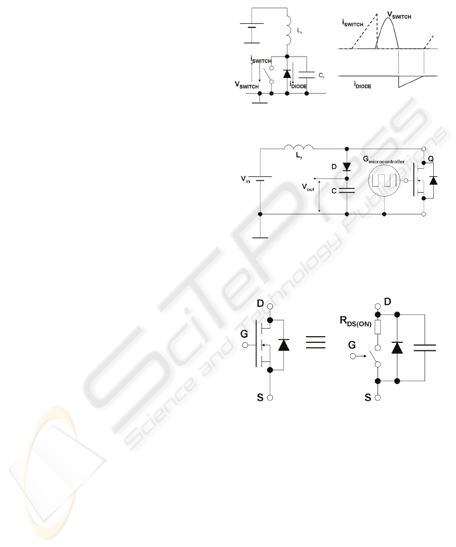
Figure 2: Zero Voltage Switch circuit and waveforms.
Figure 3: Circuit diagram of the switching resonant
voltage elevator.
Figure 4: Simplified equivalent circuit for a MOSFET.
The proposed ES circuit uses a switching
resonant voltage elevator (SRVE) to generate
voltage pulses, as shown in Figure 3. The resonance
tank is composed by an inductor L
R
and the
MOSFET parasitic capacitance shown in more detail
in Figure 4. Hence, the resonating capacitor is
already built-in in the MOSFET. The circuit in
Figure 3 applies the ZVS method, in a similar way to
the circuit displayed in Figure 2. The MOSFET
performs the switching, but it also includes the diode
and the capacitor, so that the circuit indeed performs
the ZVS as the one in Figure 2.
The voltages across the capacitor and inductor
depend on the current supplied to the inductor
BIODEVICES 2010 - International Conference on Biomedical Electronics and Devices
90
during the switch-on period, and also on the
switching frequency and on the inductance and
capacitance values. Large voltages can thus be
generated with low power consumption and a
relatively small voltage power supply.
The high voltage generated during the switching
is then stored in the large capacitor, C, in Figure 3,
which can then be applied to the patient. Naturally,
the charge stored at each switching moment is
limited by the supplied power. The voltage is
sustained through the continuous generation of high
frequency voltage spikes controlled by the
microcontroller.
Another advantage of using high frequency
switching is that it minimizes components size and
cost. One example is the advantage taken from
MOSFET parasitic capacitances.
On the other side, it could be argued that high
frequency signals (the best results were obtained
with 1MHz switching frequencies) could suffer from
electromagnetic interferences. However, resonant
circuits produce sinusoidal currents which have
smooth changes, and hence are less prone to this
type of problems.
It should be noted that there are already some
circuits in the literature that use similar strategies for
voltage elevation (Cheng et al., 2004). However, the
solutions presented do not consider biphasic pulses
and furthermore, require using two independent
switching elements. This makes the circuit more
complex, possibly with no functional advantages.
In the present circuit, output voltage is not
directly applied to the patient. Instead, it is directed
onto a subsequent circuit (the waveform driver) as
depicted in Figure 5. This circuit is based on an H-
bridge, and was designed to control the duration and
polarity of the current that passes through the load
resistance, R
LOAD
. Control is made by two
microcontroller output signals, G
1
and G
2
. At all
moments, only one of the G
1
or G
2
signals can be in
a high state. With this procedure, biphasic pulses can
be generated since the current flows on different
senses through R
LOAD
, depending on which signal G
1
or G
2
is active. It is also possible to generate
symmetric or asymmetric pulses by changing the
duration of each G signal in the high state. The PIC
timer modules control pulse duration, pulse
frequency, and activation/rest periods of the stimulus
application.
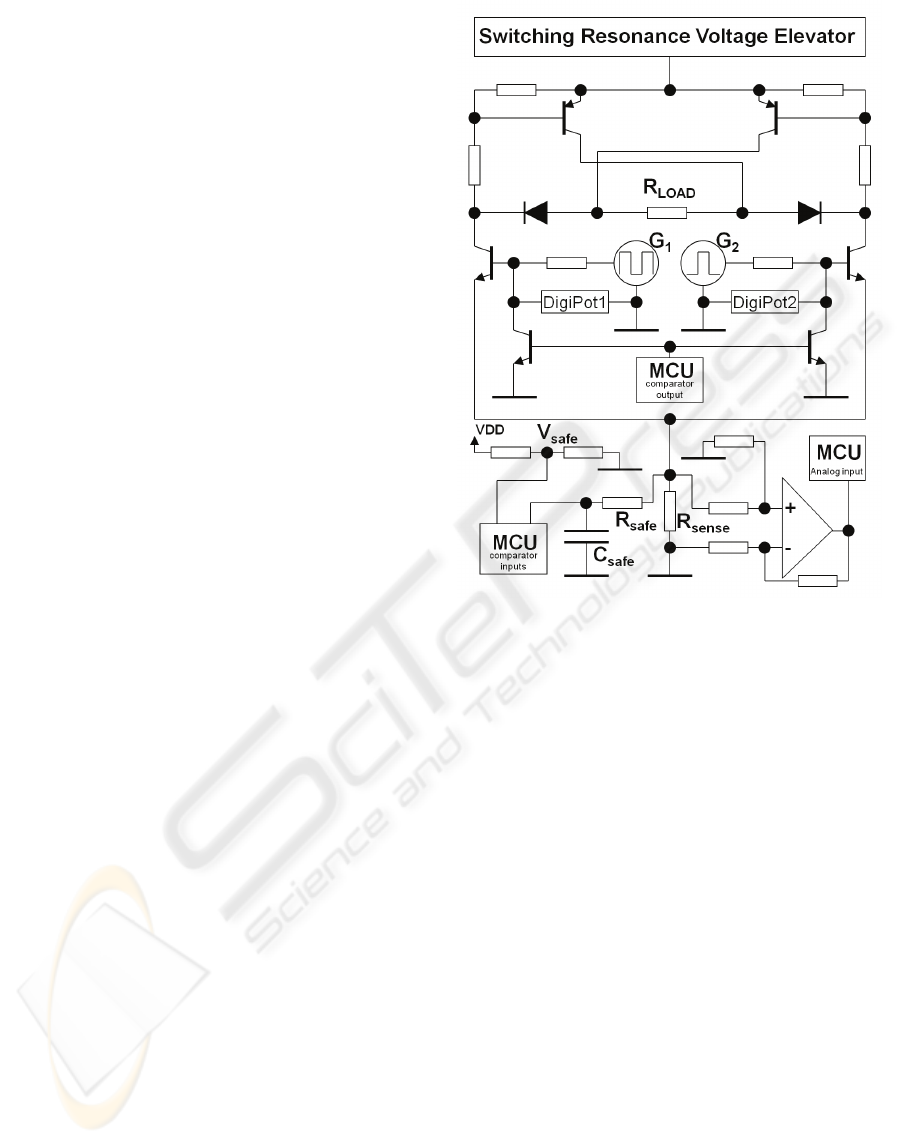
Figure 5: Scheme of the ES circuitry. It includes the
SRVE, the waveform driver, the current sensing unit and
the injected charge safety control circuits.
To stimulate excitable fibbers in a selective way
and to prevent damaging tissues in the stimulated
area, the charge flow must be controlled. As living
tissues impedance is variable, the most effective and
safe strategy, is to control waveforms in current
rather than in voltage (Merrill et al., 2005).
The circuit that controls phase amplitude
operates in a closed loop. The signals from G
1
and
G
2
are voltage divided by a resistor and a digital
potentiometer, as represented in Figure 5 by
DigiPot1 and DigiPot2, respectively. These digital
potentiometers are adjusted in real-time by the PIC
microcontroller, controlling the voltage at the
MOSFET gate and limiting the maximal current
through R
LOAD
. This current is measured by an
analogue input to the PIC, after amplifying the
voltage drop across the small R
sense
resistor.
The presented ES system incorporates a circuit to
limit the charge injected for safety purposes. The
charge increases with the amplitude of the current
and the phase duration. The maximal current
allowed was designed taking into account the
electrode-tissue interface area to avoid hazardous
charge densities (Shannon, 1992). This depends on
DEVELOPMENT OF AN INTEGRATED ELECTRICAL STIMULATION SYSTEM WITH FEEDBACK FOR
PHYSICAL REHABILITATION
91

the size of the electrodes used. The capacitor C
safe
in
Figure 5 is charged by the small voltage drop across
R
sense
. The comparator module of the microcontroller
used is programmed to automatically shutdown the
PWM signal used in the SRVE when the voltage
across C
safe
reaches V
safe
. At the same time, the
comparator output pin pulls down the gates of the
waveform driver circuit to values below the
conduction threshold. In case of undesired charge
densities, the voltage elevation and the current flow
across R
load
stops immediately.
Feedback information is measured by a 3-axis
digital accelerometer MMA7456L manufactured by
Freescale Semiconductor. This sensor is applied in
functional electrical stimulation.
4 EXAMPLE OF APPLICATION
In this section we present an example of application
of the feedback ES device described above. The
prototype used is shown in Figure 6. The circuit is
powered by a 9V battery.
Figure 6: Image of the electrostimulator prototype.
Figure 7: Snapshot of the oscilloscope monitor displaying
a biphasic pulse as obtained experimentally with the
prototype. 10x amplified probes were used in this picture.
Figure 7 shows a biphasic pulse obtained
experimentally with this prototype. For the purpose
of this figure a load resistance of 10kΩ was used.
The pulse is symmetric and biphasic. It has a pulse
duration of 300μs, an interphase interval of 50μs and
12mA of phase amplitude.
For a matter of illustration of the prototype at
work we designed an experimental protocol that
consisted of applying ES stimuli on the biceps of
healthy subjects to produce non-voluntary
movements. It was defined that the amplitude of the
stimulation should never exceed 17mA.
Furthermore, the amplitude of the ES should
decrease anytime the arm reached a maximal angle
of 83º (see Figure 8) and it should increase again if
the arm fell below 41.5º.
Figure 8: The ES exercise applied to the biceps of a
healthy subject. In this figure we also show how the
amplitude of the arm movement was measured has a result
of the applied electrical stimulation.
Typical examples of the results obtained are
shown in Figure 9. In the two exercises reported
different ES frequencies were applied. It can be
observed that the amplitude of the electrical
stimulation never exceeds the pre-defined threshold
value and that the evolution of the electrical
stimulation changed whenever the arm overcame the
maximal predefined amplitude of the movement.
These results clearly show a frequency dependent
muscle response that can be characteristic of muscle
fibre type composition which can be valuable for
clinical purposes.
BIODEVICES 2010 - International Conference on Biomedical Electronics and Devices
92
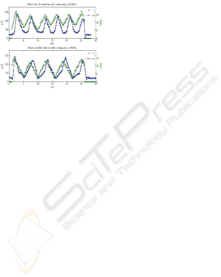
Figure 9: The amplitude of the arm movement, θ (in stars),
and of the applied electrical stimulation (triangles) as a
function of time. The stimulation frequencies were 30Hz
(Top) and 50Hz (Bottom).
5 CONCLUSIONS
This article presents an inexpensive small-sized
transcutaneous electrical stimulator unit capable of
integrating feedback information arising from a
digital accelerometer with electrostimulation. The
delivered pulsed currents can be controlled in real
time and according to a programmed protocol, on a
number of parameters - pulse duration and
amplitude, pulse rate, the type of current modulation
(burst, interrupt or ramp modulation).
In the future more elaborate ES programs should
be developed to deliver optimal ES adjusted to a
patient’s needs. These programmes can use higher
computational power and sophisticated theoretical
models of muscle function, to design the most
efficient ES programmes.
ACKNOWLEDGEMENTS
This work was supported by FCT project RIPD /
SAU-OBS / 63630 / 2005. ED is supported by FCT
SFRH / BD / 31218 / 2006.
REFERENCES
Al-Majed, Abdulhakeem A., Neumann, Catherine M.,
Brushart, Thomas M., Gordon, Tessa, 2000. Brief
Electrical Stimulation Promotes the Speed and
Accuracy of Motor Axonal Regeneration, The Journal
of Neuroscience.
Buckley, D. C., Kudsk, K. A., Rose B., Koetting C. A.,
Schlatter M., Miller C. A., 1987. Trans-cutaneous
Muscle Stimulation Promotes Muscle Growth ni
Immobilized Patients, Journal of Parenteral and
Enteral Nutrition.
Cheng, Eric K.W., Tong, Lu, Yan, Tong, Kai-Yu, Rad,
A.B., Chow, Daniel H.K., Sutanto, Danny, 2004.
Development of a Circuit for Functional Electrical
Stimulation, IEEE Transactions on Neural Systems
and Rehabilitation Engineering, Vol. 12, No.1, March.
Doucet, Barbara M, Griffin, Lisa, 2008. Maximal versus
submaximal intensity stimulation with variable
patterns, Muscle and Nerve.
Durfee, W. K., 1999. Electrical stimulation for restoration
of function, Neurorehabilitation.
Franz, C. K., Rutishauser, U., Rafuse, U. F., 2008.
Intrinsic neuronal properties control selective
targeting of regenerating motoneurons, Oxford Univ
Press.
Hennings, Kristian, Kamavuako, Ernest Nlandu, Farina,
Dario, 2006. The recruitment order of electrically
activated motor neurons investigated with a novel
collision technique, Clinical Neurophysiology.
Kitchen, Sheila, 2002. Electrotherapy: Evidence-Based
Practice, Churchill Livingstone, 11
rd
edition.
Langzam, E., Nemirovsky, Y., Isakov, E., Mizrahi, J.,
2006. Muscle enhancement using closed-loop
electrical stimulation: Volitional versus induced
torque, Journal of Electromyography and Kinesiology.
McPartland, M. D., Mook, D. J., 1995. A Robust
Transcutaneous Electro-Muscle Stimulator (RTES) - A
Multimodality Tool, Medical Engineering & Physics.
Merrill, Daniel R., Bikson, Marom, Jefferys, John G.R.,
2005. Electrical stimulation of excitable tissue: design
of efficacious and safe protocols, Journal of
Neuroscience Methods.
Neacsu, Dorin O., 2006. Power-Switching Converters
Medium and High Power, CRC Press.
Nelson, Roger M., Hayes, Karen W., Currier, Dean P.,
1999. Clinical Electrotherapy, Appleton & Lange.
Stamford, Connecticut, 3
rd
edition.
Pan, Feng, Samaddar, Tapan, 2006. Charge Pump Circuit
Design, McGraw-Hill.
Pressman, Abraham I., 1998. Switching Power Supply
Design, McGraw-Hill, 2
nd
edtition.
Shannon, Robert V., 1992. A Model of Safe Levels for
Electrical Stimulation, IEEE Transactions on
Biomedical Engineering, Vol. 39, No. 4, April
Vrbová, Gerta, Hudlicka, Olga, Centofanti, Kristin
Schaefer, 2008. Application of Muscle/Nerve
Stimulation in Health and Disease, Springer Science +
Business Media B.V.
Ye, Hong, Luo, Fang Lin, 2004. Advanced DC/DC
Converters, CRC Press LLC.
DEVELOPMENT OF AN INTEGRATED ELECTRICAL STIMULATION SYSTEM WITH FEEDBACK FOR
PHYSICAL REHABILITATION
93
