
A PROCESS FOR COTS-SELECTION AND MISMATCHES
HANDLING
A Goal-driven Approach
Sodany Kiv, Yves Wautelet and Manuel Kolp
Info. Syst. Research Unit (ISYS), University of Louvain, Belgium
Keywords:
Requirements engineering, COTS-based software development, i*, NFR, Multi-agent system.
Abstract:
Organizations facing the difficulties and costs associated with the development of their information systems
from scratch turn to use commercial off-the-shelf (COTS) products to build their systems. A crucial factor in
the success of such project is to perform a good COTS decision-making process, a process that aims at defining
the organizations’ requirements, evaluating existing products and selecting the one that best fits requirements.
However, even the best-fitting product would not perfectly match requirements, this is referred to as COTS
mismatches. These mismatches occur as a result of an excess or shortage of COTS capabilities. Many of these
mismatches are resolved after the COTS selection. This paper presents a goal-driven agent-oriented approach
for proceeding the COTS decision-making and analysing mismatches during and after the COTS selection.
The methodology is overviewed and illustrated on a case study.
1 INTRODUCTION
Nowadays software developments become huger
while development budgets tend to be lower in cri-
sis times. To deal with such an environment, COTS-
based software development is an interesting area.
With such an approach, no need to develop the soft-
ware from scratch but rather to customize an exist-
ing solution. There are several definitions of COTS
(Ayala, 2008). In this paper, we refer to generic soft-
ware products that are developed by a third party for
clients. Due to the commercial potential of software
reuse, the known similarities between the businesses
and the open source movement; software packages at
disposal tend to be larger so that consumers can seek
products meeting their requirements in a broader area.
The development of COTS-based systems mainly
depends on performance of the COTS selection pro-
cess. This process consists of defining the organi-
zations’ requirements, evaluating existing products
and selecting the one that best fits the requirements.
Several approaches have been proposed to model
the COTS selection processes (see (Ayala, 2008)).
These approaches emphasize the importance of re-
quirements analysis in order to conduct a successful
selection. In this paper, we aim to take the benefit
of goal-driven requirements engineering and agent-
orientation for modelling complex systems to im-
prove COTS-based software development. We pro-
pose a goal-driven agent-oriented methodology for
COTS selection as well as analysing mismatches be-
tween COTS components and stakeholders’ require-
ments during and after selection.
Section 2 overviews the problem and positions the
paper while Section 3 explains the methodology itself.
Section 4 illustrates the methodology application on a
case study and Section 5 finally concludes the paper.
2 PROBLEM STATEMENT
This section introduces COTS-based software devel-
opment and the advantage of adopting agent-oriented
modeling and design into COTS-based developments.
It positions the paper and briefly overviews related
work.
2.1 COTS-based Software Development
COTS-based software development (CBSD) is based
on the idea of building new systems using COTS
products, rather than developing systems from
scratch. It has become a strategic field for building
large-scale and complex systems due to its potential
benefits that are mainly its reduced costs and shorter
98
Kiv S., Wautelet Y. and Kolp M. (2010).
A PROCESS FOR COTS-SELECTION AND MISMATCHES HANDLING - A Goal-driven Approach.
In Proceedings of the 2nd International Conference on Agents and Artificial Intelligence - Artificial Intelligence, pages 98-106
DOI: 10.5220/0002732700980106
Copyright
c
SciTePress

development time, while maintaining quality. Ac-
cording to (Vigder et al., 1996), there are different
ways of using off-the-shelf software. This paper deals
with the buy-and-adapt approach. It is characterized
by acquiring a single (or very few) complete working
system(s) that satisfies most of the stakeholders’ re-
quirements and adapting and extending it to support
organizations’ goals.
The CBSD approach has raised a tremendous
amount of interests both in the research community
and in the software industry. Following (Brown and
Wallnau, 1998; Pour, 1999), the main advantages of
the CBSD approach are:
• better management of the application complexity;
• decrease of the development cost and time;
• increased flexibility;
• increased quality (mature solutions from which
correctness has been established in earlier
projects).
Although the CBSD promises significant benefits,
there are some technical problems that limit their use.
Among those problems, we find:
• how the business requirements must be captured
and refined, based on a process that leads to the
development of a COTS-based system;
• how the different COTS products must be put to-
gether and deployed using the latest technologies;
• how to select the COTS products that are the clos-
est to the developers’ needs;
• how to handle the mismatches between the COTS
capabilities and the system requirements.
The methodology proposed in this paper partially
addresses these issues.
2.2 An Agent Approach for CBSD
The paper introduces a requirements-driven method-
ology for COTS-based software development using
the agent paradigm at analysis and design stages.
The factor that really makes agent-oriented soft-
ware engineering distinct from any other software
engineering paradigm is the higher level of abstrac-
tion employed in the development of software sys-
tems. The idea of modelling a system in terms of
autonomous entities with characteristics similar to hu-
mans introduces a close-to-real-life modelling of the
system, and therefore makes the development of the
software system natural. Moreover, an agent is a goal-
driven entity with autonomy and self-control of capa-
bilities (Jennings and Wooldridge, 1999). Thus, goal-
oriented analysis has been used in agent-oriented re-
quirements engineering.
In what sense can our approach be considered as
agent-oriented?
• At analysis stage. The i* (i-star) framework (Yu,
1995), which directly introduces organizational
and social concepts - proper to an agent ontology
- into software modelling is used. This choice has
been made to better match the representation of
the organization the software system has to be de-
veloped in.
• At design stage. On the basis of the analysis dia-
grams, a MAS is designed. This is architecturally
made of a set of agents owning a series of capabil-
ities that the COTS components have to execute
for goal realization. This architecture furnishes
designers and developers scenarios that should be
included into the software application using dele-
gation to software components. The whole system
is adaptive and follows a non-monotonic logic;
the component selected by an agent to perform a
given capability at one time will evolve with con-
textual changes within the software system. This
ensures independence between requirements and
available COTS source code.
2.3 Paper Position
(Alves and Finkelstein, 2003) distinguishes, when
studying a COTS component functional aspects, two
main levels of agregation: goal and subgoal on the
one side and feature on the other. Goals are, in that
paper, based on the definition found in KAOS (Lam-
sweerde, 2001) and features are defined in the paper
as a set of features implemented by the COTS product.
Our approach is to define two processes in paral-
lel. On the one side we proceed with a classical RE
approach using i* (i-star) models with the i* goals re-
fined in a set of agent capabilities (see 3.2.1). On the
other side COTS components are analyzed in a set of
goals, subgoals and features as defined in (Alves and
Finkelstein, 2003). i* goals can then be directly com-
pared to COTS goals and subgoals and agent capabil-
ities can be compared to agent capabilities for han-
dling the differencies between the expected and the
furnished (called mismatches) on a two level basis.
Elements of the different diagrams however need
further definition to be compared. Indeed, the weak-
nesses of the elements defined in i* models are iden-
tified in (Estrada et al., 2006) and particularily con-
cerns the goal definition. In the models developed
here we rely on the definition of (Wautelet, 2008) for
modeling goals. This definition is in accordance with
the one of (Lamsweerde, 2001) used in (Alves and
Finkelstein, 2003). In the same way the conceptual
A PROCESS FOR COTS-SELECTION AND MISMATCHES HANDLING - A Goal-driven Approach
99
model of agent capabilities in 3.2.1 has been defined
for being in accordance with the (Alves and Finkel-
stein, 2003) feature definition.
Following (C. Abts and Clark, 2000; Boehm et al.,
2003), CBSD includes five phases:
• requirement engineering (RE);
• COTS evaluation and selection;
• COTS mismatches handling;
• COTS integration and system evolution.
This paper proposes a framework that covers the
four first steps depicted above. Indeed, it uses the
i* (i-star) (Yu, 1995; Yu, 1997) framework for RE.
i* goals are then further studied using an NFR goal
graph (Chung et al., 2000) for being compared to the
COTS goals in order to evaluate and select COTS
components (macro-level for COTS study). Then an
agent design model allows to distinguish the lower
level functionalities (called capabilities) that should
be fulfilled by the component’s features. This part
concerns handling mismatches after a component
has been selected (micro-level study). The integration
of methods for COTS integration and system evolu-
tion is left for future work. This process is depicted
in detail in the rest of this paper.
3 THE METHODOLOGY
The methodology for COTS-based software develop-
ment presented in this paper proposes a two level (mi-
cro and macro) analysis and design framework. First
of all, a classical RE using i* diagrams and the NFR
goal graph is performed for COTS selection (macro-
level approach). Then a MAS design allows to de-
termine at lowest level (in the form of agent capabil-
ities) the functions that must be fulfilled by the com-
ponent to handle mismatches (micro-level). Those are
overviewed in this section.
3.1 Macro-level Approach: COTS
Selection
Our framework is proposed to facilitate a systematic,
repeatable and requirements-driven COTS selection
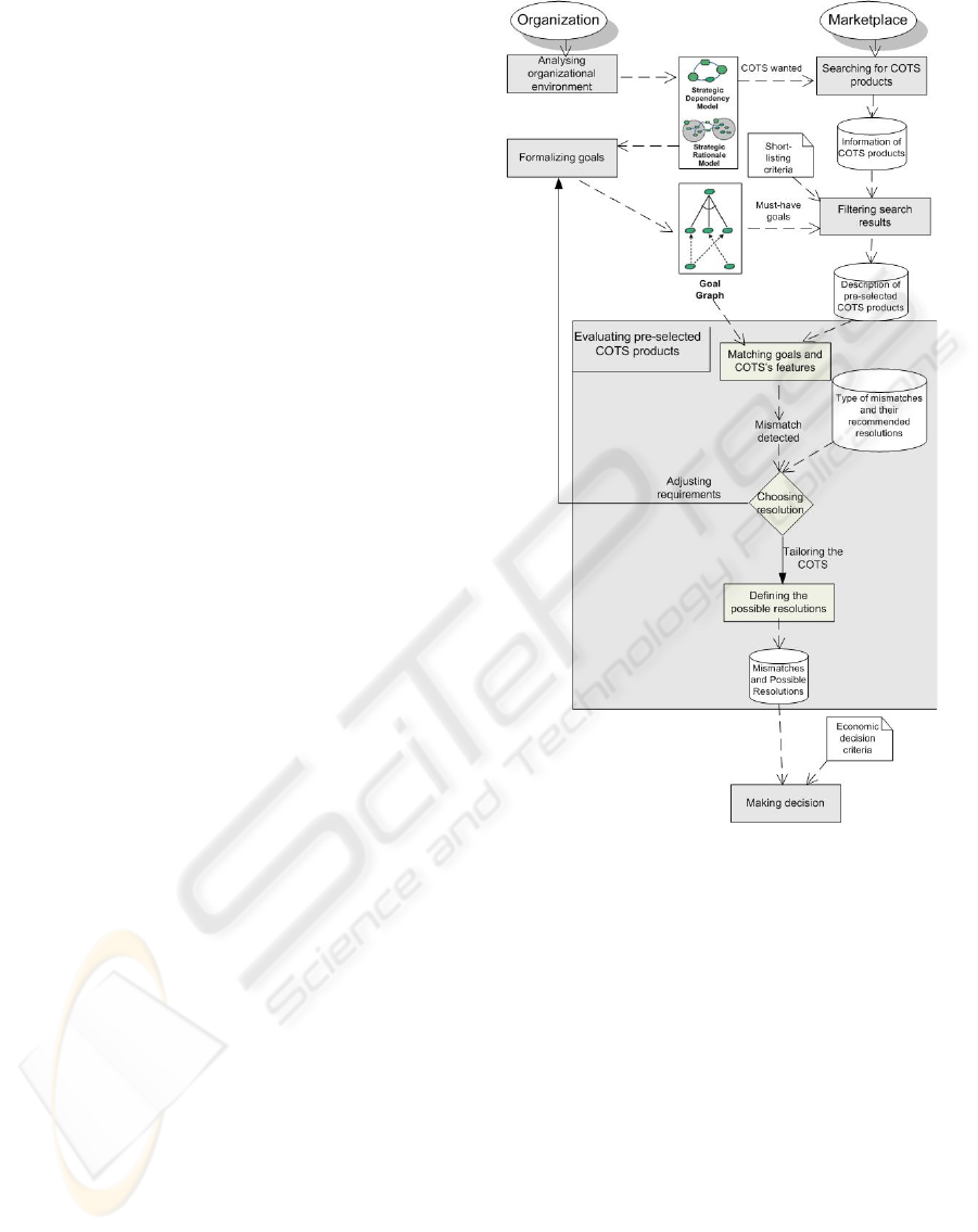
process. Figure 1 represents the different steps re-
quired to fulfull the analysis. Those steps are in accor-
dance with the definition of a SPEM WorkDefinition
(see (OMG, 2005)).
• Analysing organizational environment. This in-
volves analysing the organization where the sys-
tem will operate. The output of this activity is an
Figure 1: Overview of our COTS selection process.
organisational model, which includes relevant ac-
tors who can be human or software, their goals
to pursue, and their respective dependencies. We
propose to use the i* organizational modelling
framework (Yu, 1995).
• Searching for COTS products. This involves
searching for required software in the market-
place. The output of this work is the information
about the available COTS products in accordance
with requirements.
• Formalizing goals. This consists of making
a goal graph with the help of the i* model
where tasks are depicted as operational goals and
non-functional requirements are analysed using
the NFR framework proposed in (Chung et al.,
2000).For prioritizing goal, we associate each
goal with a degree of desirability:
ICAART 2010 - 2nd International Conference on Agents and Artificial Intelligence
100
– Very high: Very critical goal that must be ful-
filled otherwise the success of the project will
be strongly compromised.
– High: Critical goal that must be fulfilled other-
wise the success of the project will be compro-
mised.
– Medium: Important goal that should be fulfilled
in order to ensure that significant goals will be
satisfied.
– Low: Desirable goal that could be interesting to
have but that does not affect the success of the
system.
– Very low: Slightly desirable goal that does not
affect the success of the system.
This allows to distinguish the key features that
should be taken into account when proceeding
COTS evaluation and selection. This work should
be done in parallel with the searching for COTS
products in the marketplace.
• Filtering search results. This involves eliminat-
ing the COTS products according to a short-list
criteria and those that do not provide any possibil-
ities to fulfil the must-have goals, and acquiring
more information on the short-listed candidates.
The following is an example of short-listing crite-
ria:
– Vendor size. Is the vendor too big to pay atten-
tion to us? Or is the vendor too small to survive
and provide consistent service?
– Domain knowledge. What are the target domain
and market of the vendor? Do they correspond
with the company’s needs?
– Consultant service. Does the vendor pro-
vide consulting services? Does the vendor co-
operate with the consultant companies?
– Vendor’s reputation and financial position.
Does the vendor have a good or bad reputation?
Does the vendor have a good financial situation
or show any sign of potential financial crisis?
– Technology. Is the technology used flexible and
long lasting?
– Price of software. Is the price of the software
acceptable?
• Evaluating the pre-selected COTS products. In-
stead of evaluating products based on detailed
and fixed selection criteria like those proposed
by other selection methods (Ncube and Maiden,
1999; Kontio, 1995).It consists of matching the
pre-selected COTS products’ features with the
goals modelled in the goal graph. When a COTS
product does not perfectly meet a specific goal as
a result of an excess or shortage of COTS capabil-
ities, the decision makers need to decide how to
handle it. The decision is made according to the
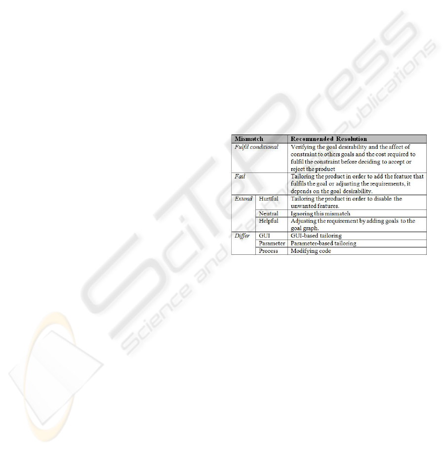
type of mismatch. Based on the literature review,
we define several types of mismatches as well as
the recommended resolutions which can be used
to support the decision-making depicted in Figure
2.If the resolution involves adjusting the require-
ments, the goal graph will be modified.The mis-
match is handled during the COTS selection pro-
cess. Otherwise, if it involves tailoring the prod-
uct, the mismatch will be analysed in order to de-
fine its possible actions and make an approximate
estimation of its complexity and risk. The mis-
match will be further analysed and resolved after
the COTS selection. In this way features might
influence the refinement of goals which leads to a
very interactive and collaborative process. More-
over, the complexity of mismatches handling after
the COTS selection will also be taken into consid-
eration for the COTS decision-making.
Figure 2: Mismatch resolution.
– Fulfil conditional mismatch. When there is a
constraint that has to be accomplished in order
to fully fulfil the initial goal.
– Fail mismatch. When a goal cannot be satisfied
by the evaluated COTS.
– Extend mismatch. When the evaluated COTS
has features that are not requested by the stake-
holders. The Extend mismatch can be:
∗ Hurtful - when an extra feature has a negative
impact over a particular goal.
∗ Neutral - when an extra feature does not inter-
fere with the achievement of any goal nor the
stakeholder want it.
∗ Helpful - when an extra feature is useful and
can be included in the system requirements.
– Differ mismatch. When the evaluated COTS
partially satisfies all the constraints imposed by
the goal. There are three different levels of Dif-
A PROCESS FOR COTS-SELECTION AND MISMATCHES HANDLING - A Goal-driven Approach
101
fer mismatch: GUI, parameter, and process lev-
els.
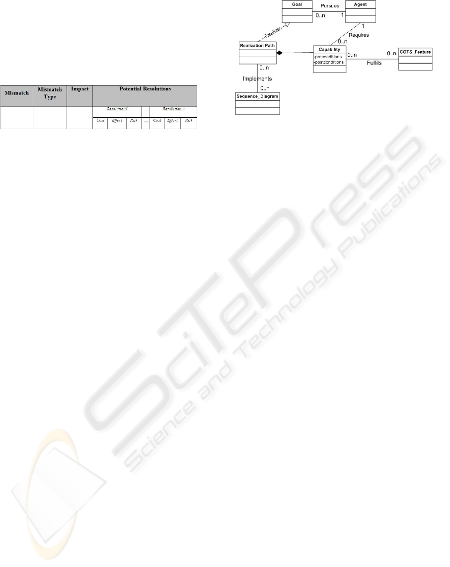
We also propose a template illustrating in Figure
3 for documenting the mismatches of each COTS
product that will use as a part of the decision-
making support.
Figure 3: Mismatch documentation template.
• Making decision. It involves making the decision
on the COTS selection as well as the action plan to
handle the mismatches based on the COTS evalu-
ation result. The result of the evaluation is a tech-
nical factor for making the decision. However,
this decision is also based on the economic aspect.
3.2 Micro-Level Approach: Mismatches
Handling
In this section we depict the micro-level. At this
level we design an agent model as a set of capabili-
ties which can be directly compared to COTS features
as defined in (Alves and Finkelstein, 2003).
Goals identified at previous stage are mapped into
a series Agent Capabilities which are a set of atomic
functions that must be fulfilled by the COTS com-
ponent. The sequence of agent capabilties resolves
a specific goal.
3.2.1 Agent Capabilites: A Conceptual Model
In this section, we will bring the agent capabilites
model to further formalization. Figure 4 depicts
the relevant concepts and their dependencies using a
UML class diagram notation. The model is structured
as follows: the agent pursues a series of intentions
modeled as goals and are then resolved through a se-
ries of capabilities in the form of a realization path.
When developing the agent concepts into a UML se-
quence diagram, capabilities are mapped in the form
of messages, agents are represented through classes
and realization paths implemented by the sequence
diagram success scenarios.
Definition 1. A tuple h{(cp
i
, q
a
cp
i
), . . . ,
(cp
i+m
, q
a
cp
i+m
)}, Ag
a
i is called an agent a, where cp
i
is a capability. The agent advertises its capability
to participate to a goal realization with defined
QoS level and cost q
a
cp
i
. The advertised level is a
vector of QoS- and cost-property and value pairs
Figure 4: A capabilities meta-model.
following a QoS ontology. Ag
a
is assumed to contain
all additional properties of the agent irrelevant for
the present discussion, yet necessary when building a
MAS.
Format and content of Ag
a
will depend on the pro-
gramming language being used. A Capability is part
of a Goal realization.
Definition 2. A capability cp
i
is hcp
pre
i
, τ
i
, cp
post
i
i,
where cp
pre
i
describes the capability precondition, τ
i
is a specification (in some language) of how the agent
is to execute the capability, and cp
post
i
describes the
conditions true after the capability is executed. Ca-
pabilities belong to the set CP.
Definition 3. hr p
ι
j
, rp
c
cp
j
, rp
a
cp
j
, rpTransit
j
, rpState
j
i
is a realization path rp
j
, where rp
ι
j
provides the de-
tails of the functional specification of the realized
goal, (r p
c
cp
j
, rp
a
cp
j
) defines a sequence diagram where
rp
c
cp
j
represents the series of capabilites required to
realize a goal and r p
a
cp
j
the agents performing them.
The two functions label swimlanes and messages with
capability information: rpTransit
j
: r p
c
cp
j
7−→ CP is
a partial function returning the capability for a given
message in the sequence diagram, while rpState
j
:
rp
a
cp
j
7−→ {cp
pre
i
}
cp
i
∈CP
∪ {cp
post
i
}
cp
i
∈CP
maps each
message to a condition from the set of all capability
preconditions (i.e., {cp
pre
i
}
cp
i
∈CP
) and postconditions
(i.e., {cp
post
i
}
cp
i
∈CP
). The capability specified on a
message must have the precondition and postcondi-
tion corresponding to conditions given, respectively,
on its origin and its destination swimlane.
Capabilities can thus be understood as a functional
decomposition of a goal with the realization path as a
success scenario. The functional specification of the
capability, rp
ι
j
, is not of interest here but depends of
the programming language and other implementation
considerations.
By conceptualizing the realization path as sug-
gested in Def.3, the service is thus mapped onto a se-
quence diagram SeQ where each swimlane is a step
ICAART 2010 - 2nd International Conference on Agents and Artificial Intelligence
102
in goal realization and a message in SeQ corresponds
to the execution of a capability cp
k
by an agent a
SA
k,u
,
where u ranges over agents that can execute cp
k
ac-
cording to the criteria set in the goal. Each path from
the starting agent (e.g., agent Agent
k
in Figure 3) to
the ending agent (also agent Agent
k
in Figure 3) thus
corresponds to a sequence of capabilities ensuring the
completion of the goal within the prescribed QoS. A
realization path could be hcp
k
, cp
k+1
, ..., cp
k+n
i. The
model thus assumes that there are alternative ways for
completing the goal. The topology of the sequence
diagram—i.e., the agent structure and the capabili-
ties associated to messages between the agents—is
provided by the designer through the goal definition,
so that the sequence diagram is a graphical model of
the different ways the goal can be performed as a se-
quence of capabilities.
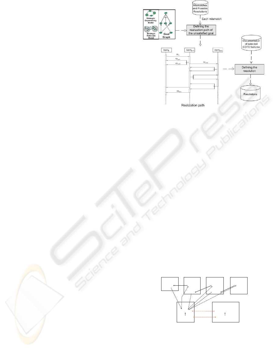
3.2.2 The Process
An overview of the process for analysing the mis-
matches that require the COTS customization to be
resolved is depicted in Figure 5. It consists of the fol-
lowing activities:
• Defining realization path. For each mismatch that
will be handled by COTS customization, we de-
fine the realization path of the unsatisfied goal. A
realization path is a set of functions (called capa-
bilities) the agent should answer to for realizing a
goal. We use the UML sequence diagram to repre-
sent the realization path. The agents’ capabilities
are then listed in a table with a name, informal
definition and the name of the agent the capability
belongs to. The set of capabilities constitutes an
abstraction level between the organizational anal-
ysis and the technology in which the COTS is im-
plemented.
• Defining resolution. Based on the realization path
and the documentation of the selected COTS fea-
tures, we define the causes of mismatches and res-
olutions to handle them. Resolution are envisaged
on a case by case basis.
4 CASE STUDY
This section overviews the application of the pro-
posed methodology onto a case study issued of supply
chain management and more particularly outbound
logistics. In this case study, we consider COTS as a
third party component used to build the global system.
We overview the different third party components that
have to be introduced into the global system, briefly
Figure 5: Overview of our mismatches analysis process.
describe the SRD and finally focus on the adoption of
a COTS for the Transportation Management System
(TMS).
4.1 Outbound Logistics
Outbound logistics is the process related to the move-
ment and storage of products from the end of the pro-
duction line to the end user. In the context of this pa-
per we mostly focus on transportation. The actors of
the supply chain play different roles in the outbound
logistic flow. The producer will be a logistic client in
its relationship with the raw material supplier, which
will be considered as the shipper. The carrier will re-
ceive transportation orders from the shipper and will
deliver goods to the client, while relying on the infras-
tructure holder and manager. In its relation with the
intermediary wholesaler, the producer will then play
the role of the shipper and the wholesaler will be the
client.
Supplier
Shipper
Producer
Client
Shipper
Wholesaler
Client
Shipper
Final client
Client
Carrier
Scheduler
Strategic planner
Infrastructure manager
Operational planner
Strategic planner
Logistic
request
Transport
Coordination
Order
Figure 6: Material flows in the outbound logistics chain.
Figure 6 summarizes the material flows between
the actors of the outbound logistics chain. The idea
underlying the software development is to favour
these actors’ collaboration. Indeed, collaborative de-
cision will tend to avoid local equilibriums (at ac-
tor level) and wastes in the global supply chain op-
A PROCESS FOR COTS-SELECTION AND MISMATCHES HANDLING - A Goal-driven Approach
103
timisation, giving opportunities to achieve the great-
est value that the chain can deliver at lowest cost (see
(Pache and Spalanzani, 2007)). More information on
the applicative package development can be found in
(Wautelet et al., 2009).
4.2 Third Party Components
Third party components that can fulfil an amount of
the identified requirements in the context of the de-
velopment of the collaborative system e are the fol-
lowing:
• The Fleet Management System (FMS);
• The Warehouse Management System (WMS);
• The Enterprise Resource Planning (ERP);
• The Transportation Management Systems
(TMS) is computer software designed to manage
transportation operations. It aids in determining
the most efficient and most cost-effective way to
execute the movement of product(s).
4.3 Methodology Application
This section presents the application of the proposed
methodology for the selection of the Transportation
Management System for the development of a (much
larger) collaborative software system. First of all,
the i* diagrams allow enlightening the organization’s
environment and the (functional) goals depending of
the third party software, and a goal graph is drawn
to analyse both functional and non-functional ex-
pected requirements. A capability table documents
the atomic functions that should be included into the
application.
4.3.1 Macro-Level: Analysis Mismatches
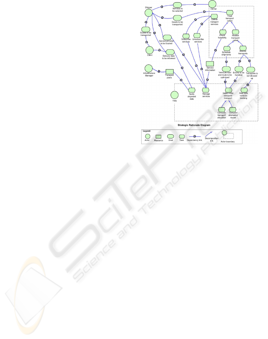
• Analysing organizational environment
Figure 7 documents the i* diagrams issued of the
organizational modelling and requirements engi-
neering of the case study. The strategic depen-
dency diagram depicts the relevant actors and
their respective dependencies. Those dependen-
cies are further analysed. The result of the anal-
ysis is depicted in the strategic rationale diagram.
It provides a more detailed level of modelling by
looking inside actors. Each outbound logistic ac-
tor depicted above (as well as the final client) and
the third party component we want to integrate in
the global system are all represented as an actor.
• Formalizing goal graph
The goal graph of Figure 8 represents both
the functional and non-functional aspects that
Figure 7: The i* diagrams.
the TMS should fulfil. Non-functional require-
ments includes Global Optimization (of the sup-
ply chain), Collaboration, Flexibility and Secu-
rity. After posing these non-functional require-
ments as goals to satisfy, we tend to refine them
into sub-goals through AND and OR decomposi-
tions and with the help of SRD. The goals that
the component should reply to are depicted in
the SRD are represented as operationalzing goals.
The interdependencies among the goals are also
studied as shown in Figure 8. The desirability of
different goals are illustrated in Figure 9.
• Selecting COTS product
Searching COTS products in the marketplace and
acquiring their documentations are not the focus of
this paper. For illustration in this case study, we
suppose that a COTS product is selected after short-
listing the available products and evaluating the pre-
selected products. Figure 10 depicted the mismatches
of the selected COTS and their resolutions. Mis-
matches that will be handled by tailoring the COTS
product will be further analysed in the next stage. Due
to the lack of space we will only focus on the one mis-
match case, Transport load and route optimization.
4.3.2 Micro-Level: Design Mismatches
• Defining realization path
ICAART 2010 - 2nd International Conference on Agents and Artificial Intelligence
104
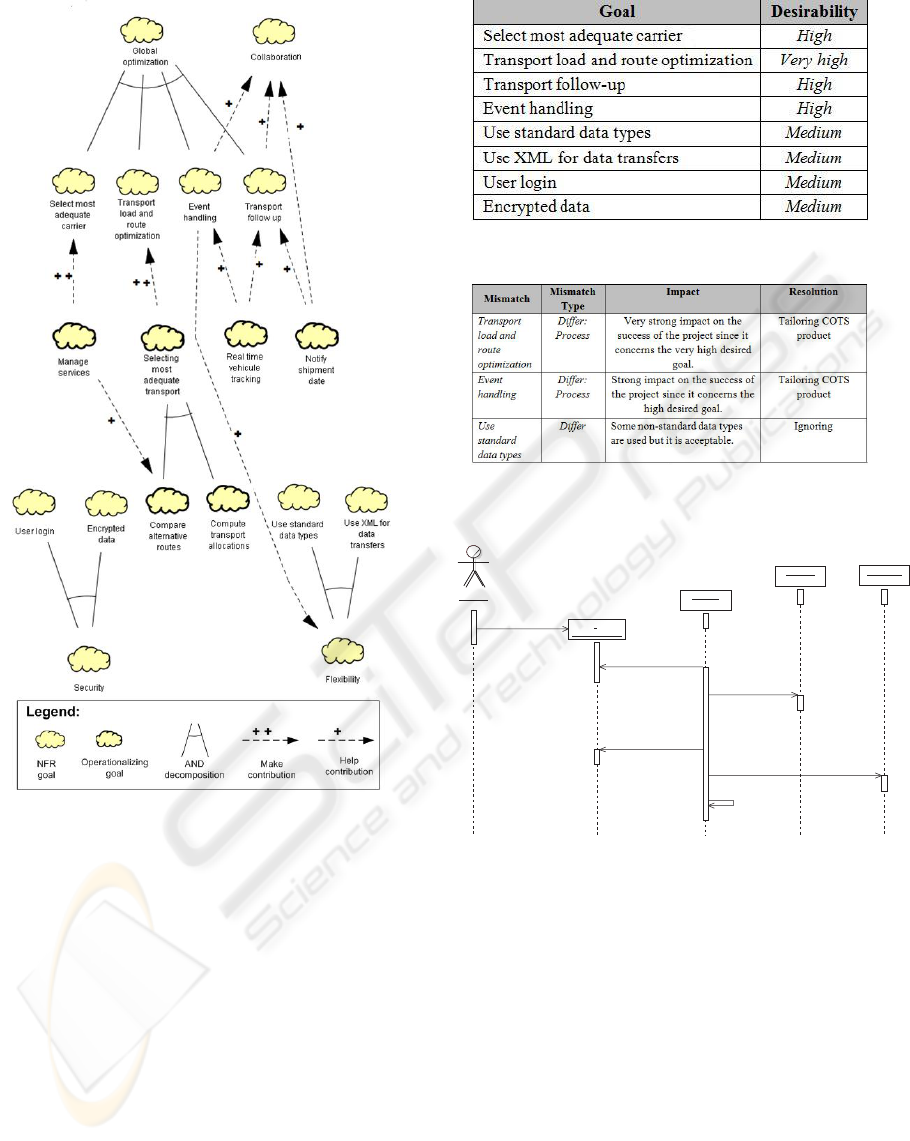
Figure 8: The goal graph.
Based on the SRD and goal graph, we now can de-
fine the realization path for the Transport load and
route optimization goal. On the goal graph of Figure
8, we can notice Selecting most adequate transport
is the mean to realize the Transport load and route
optimization goal. Figure 11 presents the sequence
diagram documenting the evoked goal’s success sce-
nario. Figure 12 depicts the capabilities list required
to fulfil this goal as well as the involved agents.
• Defining resolution
At the lecture of the table, the reader will notice
that the capabilities EvaluateLogisticRequest and Se-
lectAlternativeRoute are the only ones, involved in the
Select most adequate transport goal that are not ful-
filled through a message already implemented into the
component. For the other capabilities, existing meth-
Figure 9: The goal desirability.
Figure 10: Mismatches documentation of the selected
COTS.
: Shipper: Shipper
:
Logistic_request
:
Logistic_request
: Carrier: Carrier
: Service: Service
: Shipment: Shipment
1: createLogisticRequest( )
2: evaluateLogisticRequest( )
3: selectAlternativeRoute( )
5: DefineShipmentDate( )
6: notifyChipmentDate( )
4: recordServicesRequired( )
Figure 11: The resolution path of Select Most Adequate
Transport goal.
ods do already provide the same functional behaviour
and can be used as such or - if required - overloaded.
Consequently, the two evoked capabilities have to be
developed for adequate inclusion into the software
component so that it can achieve the documented suc-
cess scenario. The implementation of this inclusion
is not in scope of this paper since it is envisaged on a
case by case basis.
5 CONCLUSIONS
COTS-based software development constitutes a
promising area particularly in today’s crisis times
A PROCESS FOR COTS-SELECTION AND MISMATCHES HANDLING - A Goal-driven Approach
105
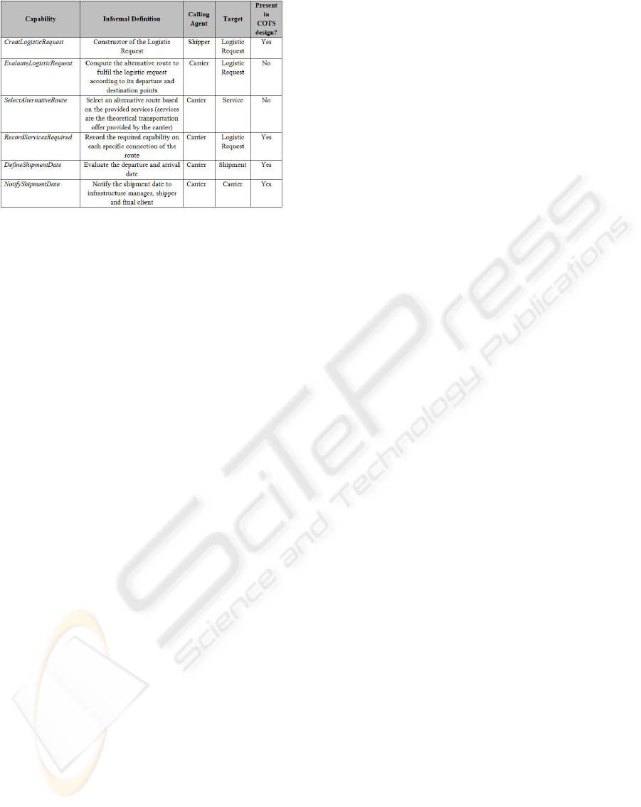
Figure 12: Capabilities required to fulfil the Select Most
Adequate Transport goal.
where costs have to be reduced as much as possi-
ble. COTS can nevertheless seldom be used as such
into an organization or into a larger software project.
Thus, those software are often conceived in a flexible
way that they can be tailored to a specific project.
As a contribution to COTS-based software de-
velopment, this paper presents a goal-driven agent-
oriented methodology for proceeding COTS selection
process and mismatch analysis during and after COTS
selection. It is part of the effort for better integrating
requirements into COTS-based software development
and analysing mismatches.
Further work notably includes extendent the
framework for COTS physical integration into the or-
ganization (deployment phase) and system evolution.
REFERENCES
Alves, C. and Finkelstein, A. (2003). Investigating con-
flicts in cots decision-making. International Journal
of Software Engineering and Knowledge Engineering,
13(5):473–493.
Ayala, C. (2008). Systematic construction of goal-oriented
cots taxonomies. PhD Thesis.
Boehm, B. W., Port, D., Yang, Y., and Bhuta, J. (2003).
Not all cbs are created equally: Cots-intensive project
types. H. Erdogmus and T. Weng (Eds.): ICCBSS
2003, LNCS 2580, pages 36–50.
Brown, A. W. and Wallnau, K. C. (1998). The current state
of component-based software engineering. IEEE soft-
ware, pages 37–46.
C. Abts, B. W. B. and Clark, E. B. (2000). Cocots: a cots
software integration cost model: model overview and
preliminary data findings. The 11th ESCOM Confer-
ence, Munich, Geremany, pages 325–333.
Chung, L., Nixon, B., Yu, E., and Mylopoulos, J. (2000).
Non-functional requirements in software engineering.
Kluwer Academic Publishers.
Estrada, H., Rebollar, A., Pastor, O., and Mylopoulos, J.
(2006). An empirical evaluation of the i* framework
in a model-based software generation environment.
Proceedings of CAiSE, pages 513–527.
Jennings, N. R. and Wooldridge, M. (1999). Agent-oriented
software engineering. In Proceedings of the 9th Euro-
pean Workshop on Modelling Autonomous Agents in a
Multi-Agent World : Multi Agent System Engineering
(MAAMAW-99).
Kontio, J. (1995). A cots selection method and experiences
of its use. Proceedings of the 2Oth annual software
engineering workshop, Maryland.
Lamsweerde, A. V. (2001). Goal-oriented requirements en-
gineering: A guided tour. International Symp. On
Requirements Engineering (RE01).Toronto, Canada.,
pages 249–263.
Ncube, C. and Maiden, N. (1999). Pore: Procurement-
oriented requirements engineering method for the
component-based system engineering development
paradigm. in International Workshop on Component-
Based Software Engineering, Los Angeles, USA.
OMG (2005). Extending i* and tropos to model security.
The Software Process Engineering Metamodel Speci-
fication. Version 1.1.
Pache, G. and Spalanzani, A. (2007). La gestion des chanes
logistiques multi-acteurs : perspectives stratgiques.
Presses Universitaires de Grenoble (PUG).
Pour, G. (1999). Enterprise javabeans, javabeans & xml ex-
panding the possibilities for web-based enterprise ap-
plication development. Proceedings of Technology of
Object-Oriented Languages and Systems,TOOLS 31,
pages 282–291.
Vigder, M. R., Gentleman, W. M., and Dean, J. (1996). Cots
software integration: State of the art. National Re-
search Council Canada (NRC), 39198.
Wautelet, Y. (2008). A goal-driven project manage-
ment framework for multi-agent software develop-
ment: The case of i-tropos. PhD thesis, Universit
catholique de Louvain, Louvain School of Manage-
ment (LSM), Louvain-La-Neuve, Belgium, August.
Wautelet, Y., Achbany, Y., Lange, J.-C., and Kolp, M.
(2009). A process for developing adaptable and open
service systems: Application in supply chain manage-
ment. In proceedings of the 11th International Con-
ference on Enterprise Information Systems (ICEIS09),
LNBIP, pages 564–576.
Yu, E. (1995). Modeling strategic relationships for process
reengineering. PhD thesis, University of Toronto, De-
partment of Computer Science, Canada.
Yu, E. (1997). Towards modeling and reasoning support for
early-phase requirements engineering. RE ’97: Pro-
ceedings of the 3rd IEEE International Symposium on
Requirements Engineering, page 226.
ICAART 2010 - 2nd International Conference on Agents and Artificial Intelligence
106
