
DETECTION OF DNA AT THE MICROCHIP
Study of DNA Detection Microchip by Oxidation Peak of DNA
Gi-sung Joo, You-Cheol Jang, Islam Atm Kamrul
Department of Nano Science and Engineering, Myongji University, Gyeonggi, Korea
Yong-Sang Kim
Department of Electric Engineering, Myongji University, Gyeonggi, Korea
Keywords: Capillary electrophoresis, Amperometry, Polyacrylamide, Microfluidics.
Abstract: We have demonstrated the separation and detection of DNA on the microchip based on amperometric with
capillary electrophoresis. To enhance analytic perfermance such as throughput and analysis time,
electrophoretic separation of DNA in capillaries or on microchips has been investigated using various
microchip structures. Compared with commonly used laser induced fluorescence method, this method is
more compatible with microchip and offer improved portability and miniaturization. Through Cyclic
voltammetric experimental, we could optimized detection voltage for detection of DNA. At the optimal
detection voltage, DNA fragments were successfully separated and detected with high sensitivity and stable
baseline.
1 INTRODUCTION
DNA analysis is important step in area of
biochemistry as well as molecular biology. In most
cases DNA is detected by fluorescent or optical
spectroscopy after agarose gel electrophoresis.
However, this procedure is tedious, time consuming
and require expensive equipments. Therefore
miniaturization of DNA analysis is necessary.
Capillary electrophoresis (CE) microchip, intro-
duced by Manz et al. in the early 1990s, alternative
for separation of biological compounds. To enhance
throughput and to shorten analysis time, electro-
phoretic separation of DNA in capillaries or on
microchips has been suggested using different
microchip structures. Optical microarrays are
arguably the most widely used type of biosensors in
DNA analysis where detection of specific DNA
sequences are based on labeling sample DNAs with
fluorophores. While fluorescence-based detection
technologies have shown tremendous utility, they
suffer from the drawbacks of labor-intensive sample
preparation, high cost, and complex and bulky
fluorescence detection instrumentation. However,
amperometric method is measured to change current
according to oxidation of analytes. Guanine and
adenine electro-oxidation is useful for the
amperometric method. Using this technique,
fragments of negatively charged DNA can be
resolved inside a capillary by application of potential.
The resolved DNA can be detected ampero-
metrically using oxidation peak of adenine base.
In the present work, we have attempted to develop
an amperometric. The microchips are usually
fabricated from silicon and glass. However,
polymeric materials are also used due to their
properties such as low cost, high flexibility, and
simply fabrication procedures. Several polymers
such as poly(dimethylsiloxane) (PDMS) and poly
(methyl methacrylate) (PMMA), polyester have
been reported for fabrication of microchip. Our
microchip was fabricated on glass substrate and
microchannels were laid in PDMS mold. The
capillary was filled with polyacrylamide gel and
separation was achieved by application of DC
potential. This technique was used in resolving DNA
fragments
117
Joo G., Jang Y., Atm Kamrul I. and Kim Y. (2010).
DETECTION OF DNA AT THE MICROCHIP - Study of DNA Detection Microchip by Oxidation Peak of DNA.
In Proceedings of the Third International Conference on Biomedical Electronics and Devices, pages 117-120
DOI: 10.5220/0002744001170120
Copyright
c
SciTePress
2 EXPERIMENTAL
2.1 Chemicals
The testing analyte was DNA ladders (100–1500 bp,
9 fragments) (Biosesang). We have used Sylgard
184 from Dow Corning Corp. (Midland, MI,USA)
and SU-8 50 photoresist and XP SU-8 developer
from Micro-Chem Co. Acrylamide: bisacrylamide
(29:1) solution was purchased from Bio Basic.
Ammonium persulphate (APS) and N,N,N’,N’-
tetramethylethylenediamine (TEMED) were bought
from Biosesang. Other reagents were purchased
from Biosesang. Deionized water (DIW) was used
throughout this research.
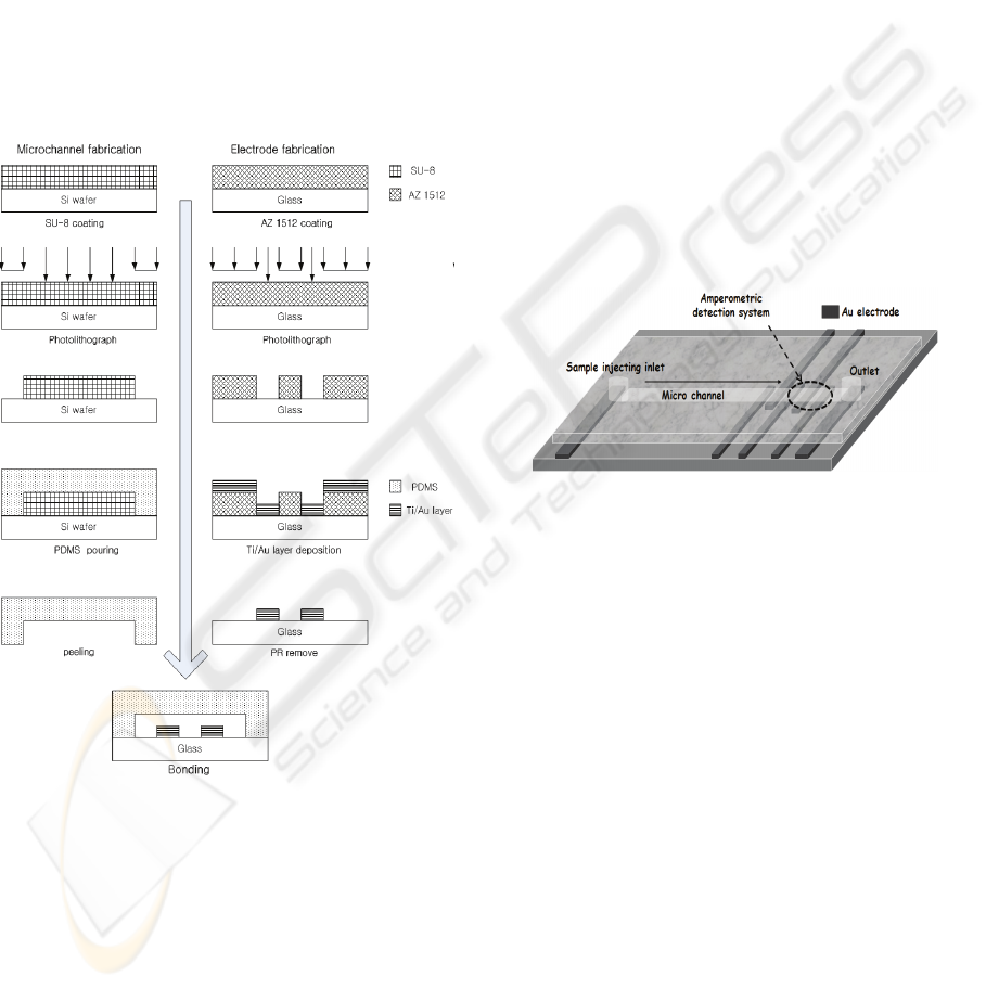
Figure 1: Fabrication process for Microchip.
2.2 Fabrication of the Microchip
Fig. 1 shows the simple procedure for the fabrication
of the CE–AD device. A silicon wafer was cleaned.
The wafer was then coated with SU-8 negative
photoresist using a spin coater. The molding masters
were made by photolithographic process. The height
of the positive patterns on the molding masters,
which were equal to the channel depth created on the
PDMS layer, was 200 μm when measured with a
surface profiler. The PDMS layer was fabricated by
pouring a degassed mixture of Sylgard 184 silicone
elastomer and curing agent (10:1) onto a molding
master, followed by curing for at least 1 h at 72 ℃.
The cured PDMS was peeled off from the mold, and
reservoirs were made at the end of each channel
using a 3 mm circular punch. The channels had a
width of 250 μm. The separation channel was 2 cm
long. The Au-electrodes for use in CE–AD were
deposited on a glass substrate by thermal eva-
poration system. For this purpose, 1.8 μm thick
photoresist (AZ-1512) was spin-coated on the bare
glass and patterned for Au-electrodes. After
evaporation, 320 nm thick Au layer was deposited
on an adhesion layer of 50 nm thick Ti. In order to
avoid the interference of high separation electric
field on amperometric detection, two decoupling-
ground electrodes were positioned in front of the
three-electrode amperometric detection system that
consisted of Au-electrodes of 250 μm width (Fig. 2).
Finally, the PDMS mold was bonded with glass
substrate after UV-ozone treatment for 40 min.
Figure 2: Schemetic of PDMS/Glass device.
2.3 Microchannel Treatment
Before use in CE–AD procedure, the microchannel
was cleaned by flushing with 1 M NaOH for 45 min
followed by D.I. water for 15 min at 5 μl/min flow
rate using a precision pump (KD Scientific, USA)
and then dried. Thereafter, 5% polyacrylamide
prepolymer solution consisting of a mixture of 875
μl Phosphate Buffered Saline (PBS), 125 μl 40%
(29:1) acrylamide/bisacrylamide solution, 1 μl TE-
MED and 4 μl 10% APS was introduced into the
microchannel. The microchip was ready for DNA
separation after 30 min of polymerization time.
2.4 CE-AD Procedure
For CE–AD, 5 μl testing sample was introduced in
the injection reservoir using a micropipette. After
the sample loading, an electric field was applied
between the sample reservoir and the sample waste
reservoir. Amperometric detection was performed
with three-electrode configuration (Fig. 2) placed in
the path of buffer flow. The potential between
BIODEVICES 2010 - International Conference on Biomedical Electronics and Devices
118
working and reference electrode was +1 V DC.
Redox reaction of adenosine from testing analyte on
the working electrode generated current peaks,
which was detected, recorded and stored directly on
a notebook computer using a CHI 800B potentiostat.
This instrument recorded 100 data points per second.
The testing analyte consisted of 9 fragments
(dsDNA).
3 RESULTS AND DISCUSSION
The CE–AD microchip developed in the present
research was used in separation and analysis of
DNA fragments. The chip was fabricated on
transparent glass substrate, which assisted in
Uvozone bonding with PDMS mold containing
microchannel as well as loading of samples into the
reservoir. The benefits of using PDMS as the
material for fabricating microchannel were its tran-
sparent color, ease in fabrication using negative
molding method, flexibility, mechanical strength and
stability. The amperometric detection system
consisted of in-channel working, counter and
reference electrodes. Two decoupler electrodes were
used to ground the separation current in order to
minimize electric noise. The choice of gold Micro-
electrodes was based on its inertness and ease in
patterning over glass substrate.
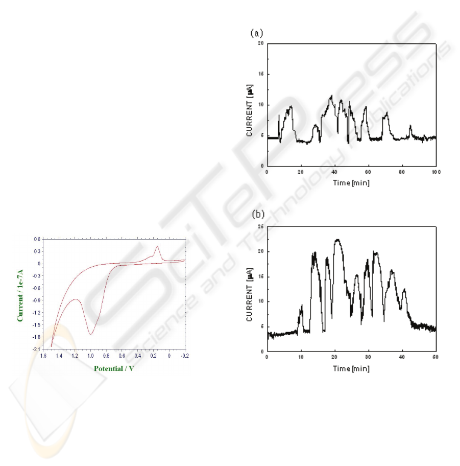
Figure 3: Cyclic voltammogram of DNA ladders in
microchip. The scan rate is 10mV/s
-1
.
The adenine and guanine base in the DNA chain is
to produce oxidation peak at +1 V DC (Fig.3).
Therefore, this potential was used for detection of
DNA fragments being separated inside the
microchannel filled with 5% polyacrylamide gel.
Although technically it was possible to resolve DNA
fragments in a narrow capillary without the use of
polyacrylamide, but that would require quite long
capillary length which may hinder the detection of
DNA due to its adsorption on long PDMS capillary
walls. Therefore, to minimize the detection time as
well as increase detection sensitivity, we used 2 cm
channel length filled with 5% polyacrylamide. The
DNA fragments were separated in the process due to
difference in molecular weight. Separation DC
potential is important factor as well as buffer
solution to enhance perfermance of device. We have
demonstrated effect of separation potential. all nine
fragments could be identified (Fig. 4 a,b) from the
Electropherogram for 85min at 100 V/cm and 40min
at 150 V/cm, repectively.
Figure 4: Electropherogram of DNA fragments using PBS
with 5% polyacrylamide for applied separation field
100V/cm (a) and 150V/cm (b).
The DNA fragments could be resolved during CE–
AD process and all nine fragments could be
identified from the Electropherogram (Fig.4). This
proved the feasibility to build a cost-effective and
power efficient microchip to analyze DNA
fragments. The specificity of proposed CE–AD
method shall depend on the presence of additional
electroactive species pro-ducing amperometric peak
DETECTION OF DNA AT THE MICROCHIP - Study of DNA Detection Microchip by Oxidation Peak of DNA
119

at + 1 V. The numbers of such species are limited in
most of the molecular biology techniques involving
DNA electrophoresis, including PCR, therefore
causing limited impact on the effectiveness of
proposed method.
4 CONCLUSIONS
In the present study, we devised a PDMS-based
microchip for capillary electrophoresis ampero-
metric detection of DNA fragments. At the cyclic
voltammetry experimental, oxidation peak of
adenine and guanine was indicated at + 1 V. The
capillary was filled with 5% polyacrylamide gel for
effective separation of DNA fragments under the
influence of separation potential. The amperometric
detection (AD) system involved in-channel gold
micro-electrodes and this technique was used in
resolving DNA fragments.
ACKNOWLEDGEMENTS
This work was supported by Grant No. ROA-2006-
000-10274-0 from the National Research Laboratory
Program of the Korea Science & Engineering
Foundation.
REFERENCES
F.M. Ausubel, R. Brent, R.E. Kingston, D.D. Moore, J.G.
Seidman, J.A. Smith, K. Struhl, Current Protocols in
Molecular Biology, John Wiley & Sons, 2003.
M.J. Schoning, M. Jacobs, A. Muck, D.-T. Knobbe, Sens.
Actuators, B 108 (2005) 688.
J.H. Kim, C.J. Kang, Y.-S. Kim, Microelectron. Eng. 71
(2004) 119.
J.H. Kim, C.J. Kang, Y.-S. Kim, Microelectron. Eng.
73/74 (2004) 864.
BIODEVICES 2010 - International Conference on Biomedical Electronics and Devices
120
