
ARCHITECTURE FOR HUMAN-ROBOT COLLABORATIVE
NAVIGATION
Sousso Kelouwani, Patrice Boucher and Paul Cohen
´
Ecole Polytechnique, 2900, boul.
´
Edouard-Montpetit Campus de l’Universit
´
e de Montr
´
eal, Montr
´
eal (Qu
´
ebec), Canada
Keywords:
Motorized wheelchair, Robotic architecture, Shared control, Three-layer architecture, Collaborative control.
Abstract:
Various situations of mobile platform navigation controls require a collaboration between a human agent and
autonomous navigation modules. This work presents a new approach for collaborative control between such
two agents, based upon a three-layer architecture. An arbitration scheme is proposed in the deliberative layer
as well as a collaborative planning method for trajectory following based upon optimal control theory in the
sequencer layer. The collaborative control signal in the execution layer is a weighted summation of each
agent control signal. This collaborative architecture could be used for the shared control of vehicles such as
motorized wheelchairs. Experimental results illustrate the efficiency of the proposed control architecture.
1 INTRODUCTION
The shared control of a robotic platform falls into
two categories: the first one corresponds to situations
where the various agents compete to find the best con-
trol action to be selected and applied (Skrzypczyk,
2005). The second category corresponds to a col-
laborative approach aiming at achieving a given goal
(S. Katsura, 2004; Q. Zeng, 2008; C. Urdiales and
Sandoval, 2007). This paper focuses on a collabo-
rative approach to shared control between a human
agent onboard a mobile platform, such as a motor-
ized wheelchair for example, and an autonomous nav-
igation module. The autonomous navigation module
relies on its proximity sensors (sonar, infrared, laser
range finder, etc.) in order to perform the naviga-
tion task; its ability to sense the surrounding envi-
ronment is therefore, limited by its perception and
interpretation capabilities. Based upon its own sen-
sory system, the human agent can contribute to ex-
tend the autonomous module capabilities by provid-
ing a control signal that allows the platform to avoid
non-detected dangers and improve its navigation per-
formance. Inversely, in situations where human per-
ception and control suffer momentarily from a lack of
attention, the autonomous navigation module may be
able to compensate and avoid imminent dangers. Fur-
thermore, various types of maneuvers in constrained
environments, such as doorway passing or parking,
may exceed the human agent capabilities and require
the help of the autonomous agent.
Previous work on collaborative navigation control fo-
cused on the decision problem (A. Huntemann and
al., 2007; T. Taha and Dissanayake, 2007; Y. Qi and
Huang, 2008; T. Okawa and Yamaguchi, 2007) (i.e.
the determination of the navigation task), while the
planning aspect, i.e. the determination of the se-
quence of platform actions that may be used) is left
to the responsibility of the Autonomous Navigation
Module (C. Urdiales and Sandoval, 2007; Q. Zeng,
2008). Usually, there are more than one sequence
of platform actions that can be used to reach a given
goal and the one selected by the Autonomous Naviga-
tion Module is not necessarily what the Human agent
would do if he was responsible of the planning. This
paper presents two contributions: the first one con-
sists of a reactive arbitration scheme that allows two
agents with different perception modalities to avoid
perceived obstacles. The second contribution consists
of a collaborative architecture that efficiently includes
both agents control signals at decision and planning
levels. In addition, we provide a formal approach to
the integration of the Human Agent plan during the
elaboration of the Autonomous Navigation Module
plan. This method is based upon the multi-agent op-
timal control theory (Cruz, 1978; Simaan and Cruz,
1973; Y. C. Ho and Olsder, 1982).
The rest of the paper is organised into 4 sections.
Section 2 presents the deliberative obstacle avoidance
scheme. In section 3, the collaborative architecture is
316
Kelouwani S., Boucher P. and Cohen P. (2010).
ARCHITECTURE FOR HUMAN-ROBOT COLLABORATIVE NAVIGATION.
In Proceedings of the Third International Conference on Health Informatics, pages 316-323
DOI: 10.5220/0002745403160323
Copyright
c
SciTePress

discussed. Experimentations and conclusion are pre-
sented in section 4 and section 5, respectively.
2 OBSTACLE AVOIDANCE
DELIBERATIVE APPROACH
2.1 Problem Statement
The main goal of this work is to design a system that
can allow a Human Agent (HA) and an Autonomous
Navigation Module (ANM) to collaborate during nav-
igation tasks of a mobile platform. Given an envi-
ronment map and the current mobile platform con-
figuration (position and orientation), the ANM agent
aims at helping the HA to reach a given destination
without colliding with obstacles, as perceived by the
ANM. The help mentioned here is related to the fact
that the ANM agent is continuously supervising the
HA control signal and intervenes only to avoid colli-
sions. Since the two agents perception systems differ,
various situations may occur in which:
• a danger is perceptible by the ANM agent alone:
we designate by S
am
the set of such events; nav-
igation control priority should be given to the
ANM;
• a danger is perceptible by the Human agent alone:
we designate by S
h
the set of such events; naviga-
tion control priority should be left to the HA;
• a danger is perceptible by both agents: we des-
ignate by S
ham
the set of such events; navigation
control should be based upon deliberation;
• a danger is not perceptible by any of the two
agents; a collision is unavoidable.
The main problem consists in establishing an arbi-
tration scheme that will produce the desired decision
scheme outlined above.
2.2 Preliminary Considerations
We assume that, at the beginning of the navigation
task, a map of the environment and the destination
configuration are available to the ANM. At each step
k, each of the two agents provides a control signal
based upon their current perception of the environ-
ment. From the perspective of the arbitration scheme
to be designed, a control signal is considered to be
safe if its application does not lead to collision for an
obstacle belonging to S
am
or S
ham
.
We designate by U
h
(k) and U
c
(k) HA and the ANM
control signals respectively. Since both agents are not
competing, a reasonable choice for the collaborative
control signal consists of selecting a weighted sum of
both signals U
h
(k) and U
c
(k). The agent with higher
priority will have the largest control signal weight.
Solving the deliberation problem is equivalent to find-
ing the weight relative to each agent. For simplicity,
we designate these weights by α(k) and (1 − α(k))
with α(k) ∈ [0, 1] where α(k) is the ANM control sig-
nal weight at step k. The following expression corre-
sponds to the collaborative control signal U (k):
U(k) = (1 − α(k))U
h
(k) + α(k)U
c
(k) (1)
Given U
h
(k) and U
c
(k), the deliberative control prob-
lem consists of determining the value of α(k) at each
step k.
2.3 Approach for Solving the
Deliberative Problem
The precedence of U
h
over U
c
must be taken into ac-
count when solving the above problem. Indeed, the
ANM should not generate its control signal without
taking into account the motion direction implied by
the HA control signal. This constraint is important in
order to allow the platform to follow the HA control
signal whenever several ways exist to safely achieve
a maneuver. For example, in front of an obstacle be-
longing to S
ham
, the HA decision on how to avoid it
must be complied with. Similarly, in the absence of
any danger, the ANM should generate a control sig-
nal U
c
close to U
h
since there is no need to help the
human agent in such a situation.
A criterion, called non-collision index P(k) ∈ [0, 1],
must be defined in order to allow the arbitration
scheme to assess the risk of a collision if one of the
two control signals were to be used alone. P(k) should
be small if a collision is likely to happen. The follow-
ing expression is a good candidate to represent the
non-collision index:
P(k) = e
−C
1
d
min
(k)
(2)
where d
min
(k) > 0 represents the minimum dis-
tance between the platform position and the nearest
obstacle in the direction of motion. The value of the
index decreasing rate C depends upon the navigation
context. Given the expression of P(k), we define the
Human agent non-collision index P
h
(k) and the ANM
non-collision index P
c
(k) as:
P
h
(k) = e
−C
1
d
min
h
(k)
(3)
P
c
(k) = e
−C
1
d
min
c
(k)
(4)
where d
min
h
(k) > 0 represents the minimum distance
between the platform configuration and the nearest
ARCHITECTURE FOR HUMAN-ROBOT COLLABORATIVE NAVIGATION
317
obstacle if only U
h
(k) was applied and d
min
c
(k) > 0
represents the corresponding distance if only U
c
(k)
was applied. Given P
h
(k) and P
c
(k), the value of α(k)
is derived as:
α(k) =
P
c
(k)
P
h
(k) + P
c
(k)
(5)
Arbitration Scheme Description
The arbitration scheme has two phases: the supervi-
sion phase and the correction phase. Let us define P
0
h
as a minimum predefined non-collision index. The
system is in the supervision phase if P
h
(k) > P
0
h
. Oth-
erwise, the system is in the correction phase.
Supervision Phase:
During this phase and at each step, the deliberative
module computes P
h
(k). If U
h
(k) leads to a safe mo-
tion, the following condition holds: P
h
(k) > P
0
h
. The
ANM generates U
c
(k) close to U
h
(k) since there is no
need to help the human agent. But the deliberative
module will set α(k) to 0 so that U(k) is exactly equal
to U
h
(k) according to equation 1. Therefore, the plat-
form is under the control of the human agent.
Correction Phase:
When P
h
(k) <= P
0
h
, a collision may happen if U
h
(k)
is applied directly. Perceiving the obstacle, as part
of S
am
or S
ham
, the ANM generates a control sig-
nal U
c
(k) in order to avoid collision. Since U
c
(k) is
safer than U
h
(k), the non-collision index P
c
(k) will be
greater than P
h
(k). According to equation 5, the value
of α(k) is greater than 0.5, allowing a greater contri-
bution of the ANM control signal into the collabora-
tive control signal. In the extreme case when U
h
(k) is
very unsafe, α(k) will be close to 1 and the collabora-
tive control signal U (k) will be close to U
c
(k).
On the basis of this arbitration scheme, the collabora-
tive control system will behave as specified in Section
2.1.
2.4 Limitation of the Arbitration
Scheme
The proposed arbitration handles correctly the three
cases mentioned Section 2.1. However, since the list
of cases was not exhaustive, the arbitration scheme
may not correctly avoid all situations of collisions.
For example, an obstacle belonging to S
h
on the left
of the platform and a second one belonging to S
am
in front of it, while the platform is moving straight-
forward, may cause the ANM to generate a control
signal U
c
(k) that will induce a motion on the left, thus
leading to a collision.
The next section presents a complete collaborative ar-
chitecture designed to test the proposed arbitration
scheme.
3 COLLABORATIVE
NAVIGATION ARCHITECTURE
The subsumption (Brooks, 1986) and the three-layer
architectures (E. Gat and Murphy, 1998) are among
well-known robotic architectures used for platform
navigation applications. The subsumption archi-
tecture is associated with reactive behaviour-based
robots. Since upper layers interfere with lower layers,
they cannot be designed independently. The three-
layer architecture consists of a Deliberative Layer for
navigation task selection, a Sequencer Layer for re-
active planning and an Execution Layer for low level
effector control. Due to its modular concept, we select
the three layer architecture as the basis of the collab-
orative control architecture presented here. This col-
laborative architecture has the advantage of providing
a high level of decoupling between layers, each layer
(deliberative, sequencer or execution layer) can be de-
signed without attention to the roles of the other layers
of the architecture.
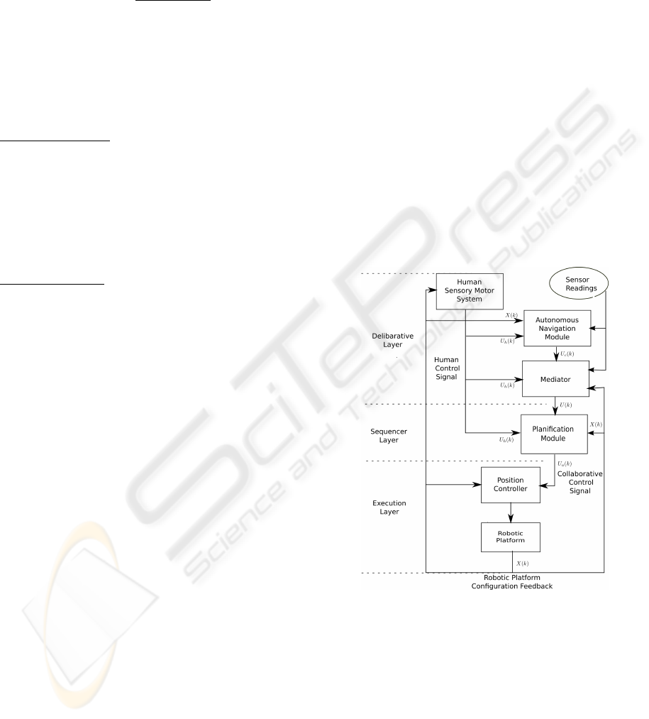
Figure 1: Collaborative Architecture for Navigation.
3.1 Deliberative Layer
The Deliberative Layer is the top layer of the pro-
posed architecture. It has the core of the ANM and
the Mediation module.
3.1.1 Autonomous Navigation Module
The role of this module is to provide at each step k a
control signal U
c
(k) that leads to safe motion. When
HEALTHINF 2010 - International Conference on Health Informatics
318
an obstacle is perceived, it uses a collision avoidance
algorithm based upon the Virtual Field Histogram ap-
proach (VFH) (Borenstein and Koren, 1991). Fig-
ure 2 illustrates how the ANM control signal can be
generated using a VFH based obstacle avoidance ap-
proach.
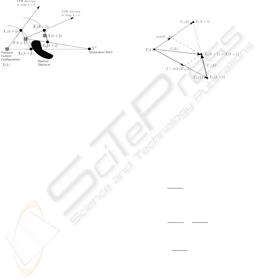
Figure 2: Trajectory Generation: At step k, the platform
receives the control signal from each agent. If the Human
control signal is applied alone, the platform configuration at
step k + 1 will be X
h
(k + 1). If the Autonomous Navigation
Module control signal is applied alone, the platform con-
figuration at step k + 1 will be X
c
(k + 1). By applying both
control signals at step k, the next platform configuration will
be between X
h
(k +1) and X
c
(k +1). This configuration will
be close to X
c
(k + 1) and X
c
(k + 1) is close to 1.
Assume that X
d
= [x
d
y
d
θ
d
]
0
is the platform des-
tination configuration and X(k) = [x(k) y(k) θ(k)]
0
is
the current platform configuration as shown in Fig-
ure 2. Based upon X(k), X
d
and obstacles around the
platform, the Virtual Field Histogram (VFH) method
is used to find the lowest obstacle density direction
for platform move (Borenstein and Koren, 1991).
This direction is called the VFH direction and defines
the orientation θ
c
(k + 1). In order to find the point
(x
c
(k + 1), y
c
(k + 1)) on that direction, we propose a
method that will allow the human agent to move and
stop the platform at will.
At step k, the HA provides its control signal U
h
(k). If
U
h
(k) is applied without any contribution of the ANM
agent control signal, the platform configuration will
be X
h
(k + 1) = [x
h
(k + 1) y
h
(k + 1) θ
h
(k + 1)]
0
. The
point (x
c
(k), y
c
(k)) is selected on the VFH direction
so that the Euclidian distance between (x(k), y(k))
and (x
h
(k + 1), y
h
(k + 1)) is the same as that between
(x(k), y(k)) and (x
c
(k + 1), y
c
(k + 1)).
3.1.2 Mediator Module
This module uses the arbitration scheme presented in
section 2.3 in order to produce the collaborative con-
trol signal U(k).
3.2 Collaborative Sequencer Layer
The HA control signal can be affected by variations
originating from the input modality uncertainty or
hand tremors. In this section, we propose an ap-
proach that significantly reduces the impact of un-
wanted variations on the collaborative control. In or-
der to present our method, let us consider the signal
control diagram shown in Figure 3.
Figure 3: Control Signal Diagram. The individual appli-
cation of U
h
(k) and U
c
(k) will produce the configuration
X
h
(k +1) and X
c
(k +1) respectively. However, due to α(k),
the collaborative control signal U(k) will produce X (k + 1).
Given the value of α(k), there are two ways to
compute the collaborative control signal U(k) shown
in Figure 3:
U(k) = α(k)U
c
(k) + (1 − α(k))U
h
(k) (6)
or
U(k) = U
a
(k) +U
h
(k) (7)
According to equation 6 and knowing that the U
c
(k)
is independent from U
h
(k), we get:
∂U (k)
∂U
h
(k)
= (1 − α(k))I (8)
where I is a (3×3) identity matrix. On the other hand,
according to equation 7:
∂U (k)
∂U
h
(k)
=
∂U
a
(k)
∂U
h
(k)
+ I (9)
If U
a
(k) is selected so that
∂U
a
(k)
∂U
h
(k)
< −α(k)I (10)
then the second way for computing U(k) is more ef-
ficient than the first method represented by equation
6. We provide a method based on the optimal control
theory that allows to select U
a
(k).
Recall that the role of the Sequencer Layer is to pro-
vide U
a
(k) given X(k), X (k + 1) and the dynamic
model of the platform. If the Execution Layer has
enough time to move the platform from X(k) to X(k+
ARCHITECTURE FOR HUMAN-ROBOT COLLABORATIVE NAVIGATION
319

1), given the control signal U(k), then its dynamic be-
havior can be approximated by the following linear
equation:
X(k + 1) = X(k) +U(k) (11)
where U(k) is represented by equation 7. In col-
laborative navigation contexts such as motorized
wheelchair control, it is useful to constrain U
a
(k) in
order to ensure smooth behavior. Large magnitudes
of U
a
(k) should be avoided and the deviation between
platform configurations X(k) and the X
a
(k) should be
minimized in order to allow the platform to follow the
sequence of X
a
. The following functional expression
takes into account the above mentioned requirements.
J
a
[U
a
(k)] =
1
2
M−1
∑
k=0
C
a
(k) +
1
2
C
a
(M) (12)
where:
C
a
(k) = [X(k) − X
a
(k + 1)]
T
Q
a
(k)[X(k) − X
a
(k + 1)]
+U
T
a
(k)R
a
(k)U
a
(k)
(13)
C
a
(M) = [X(M) − X
a
(M + 1)]
T
Q
a
(M)[X(M) − X
a
(M + 1)]
(14)
Q
a
(k) is a (3 × 3) symmetric and positive semi-
definite matrix that penalizes the deviation between
the platform configuration and the mediated configu-
ration at step k;
R
a
(k) is a (3× 3) symmetric and positive definite ma-
trix that penalizes large sequencer control signals at
step k.
The optimal sequence {U
∗
a
(k), k = 0, ..., M − 1} is,
therefore, the sequence {U
a
(k), k = 0, ..., M − 1} that
minimizes the functional expression 12 under the con-
straint 11.
3.2.1 Solving the Planning Problem
In order to solve the optimization problem, we as-
sume that the state vector is fully accessible to the
sequencer and that the initial state vector X(0) is
completely known. Furthermore, we consider that
U
h
(k), k = 0, ..., M − 1 is known. Using the Hamilto-
nian calculus (Lewis and Syrmos, 2005), we obtained:
U
∗
a
(k) = F
a
(k)X(k) + F
h
(k)U
h
(k) + F
v
(k)V (k + 1)
(15)
where:
F
a
(k) = −R
−1
a
(k)S(k + 1)F(k) (16)
F(k) = [I + R
−1
a
(k)S(k + 1)] (17)
F
h
(k) = −R
−1
a
(k)S(k + 1)F(k) (18)
F
v
(k) = R
−1
a
(k)[I − S(k + 1)F(k)R
−1
a
(k)] (19)
S(k) = S(k + 1)F(k) + Q
a
(k) (20)
V (k) = Q
a
(k)X
a
(k + 1) +V (k + 1)
+S(k + 1)F(k)R
−1
a
(k)V (k + 1)
−S(k + 1)F(k)U
h
(k) (21)
According to equation 7, the collaborative control sig-
nal is given by:
U(k) = U
∗
a
(k) +U
h
(k)
In order to reduce variations on U
h
(k), the values of
R
a
(k) and Q
a
(k) are selected so that the following
condition holds:
∂U
∗
a
(k)
∂U
h
(k)
< −α(k)I (22)
3.3 Execution Layer
We assume that the robotic platform configuration
X(k) at step k is represented by its configuration ex-
pressed in a reference frame (working space). The
Execution Layer, in the three-layer architecture, is de-
signed to be tightly coupled with sensors and actua-
tors. It receives a set point (or a target configuration)
and, through the use of one or more control loops,
tries to reach that point. However, in the proposed
collaborative architecture, the Execution Layer input
signal U(k) is a weighted sum of two control signals.
Based upon the platform dynamic equation, the cur-
rent configuration and U(k), the next configuration
is computed and used as a set point for the Position
Controller which is part of the Execution Layer. The
Position Controller needs to find a control law that
minimizes the deviation between the configuration
obtained by applying the control law and the given
configuration. Many methods exist to solve the con-
troller problem in the case of a mobile platform (As-
tolfi, 1999), (Y. Kanayama and Noguchi, 1990). Re-
cently, Belkhous (S. Belkhous and Nerguizian, 2005)
proposed a new method based on Lyapunov theory.
Since the Execution Layer is decoupled with the up-
per layers, any other platform dynamic model can be
used with a minimum architecture modification.
4 EXPERIMENTS
4.1 Experimental Setup
In order to test the proposed arbitration scheme and
the collaborative architecture, a first test scenario rep-
resented in Figure 4 is used on a mobile robotic
platform. Starting from a rest position at A(0, 0),
HEALTHINF 2010 - International Conference on Health Informatics
320
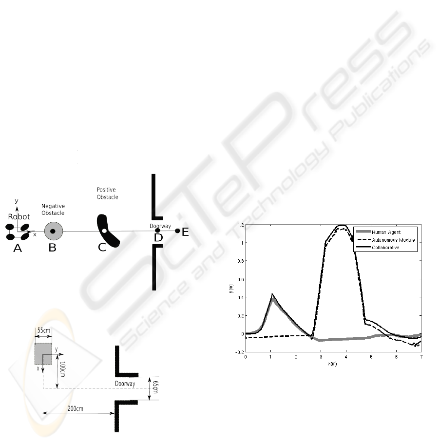
the ANM and the HA must collaborate in order to
drive the platform to the destination point E(7, 0)),
by avoiding obstacles along the way. A negative ob-
stacle is at position B(1.5, 0) and a positive obstacle
is at C(3.5, 0). Furthermore, the platform must pass
through a doorway at position D(6.2, 0) before reach-
ing destination point E. The platform has one on-
board laser range finder for obstacle detection. Due
to the ranger finder position on the platform, negative
obstacles cannot be detected. On the other hand, we
assume that the HA is capable of perceiving negative
obstacles, therefore, belonging to set S
h
. For illustra-
tion purposes, we assume that the positive obstacle at
position C is only perceived by the ANM through its
range finder. Both agents can perceive the doorway.
Hence, the positive obstacle belongs to set S
am
and
the doorframe belongs to set S
ham
.
The second scenario intends to illustrate the collabo-
ration when the obstacle belongs to S
ham
. This sce-
nario is represented in Figure 5. The mobile platform
must move forward for about 1 meter, turn in order to
face the doorframe and then move through the door-
way. The doorway opening is 65cm wide, whereas
the mobile platform width is 55cm.
Figure 4: Navigation Scenario.
Figure 5: Doorway Passing Setup.
The mobile platform used for experiments is an
ATRV-Mini manufactured by IRobot, equipped with
a SICK laser rangefinder, model LMS200. Player-
Stage (H. J. Toby and al., 2005) and Acropolis (Zalzal
and al., 2006) softwares were used for the implemen-
tation. A standard joystick was used as the human
agent input modality. The planning horizon of the se-
quencer layer is set to 1 and all involved matrices are
set to the identity matrix I, except for R
a
(k) which is
set to 10
−3
I.
4.2 Experience 1: Navigation with
Obstacle Avoidance
Figure 6 shows three examples of trajectories. The
first trajectory (grey curve) represents the Human
agent trajectory, if he was alone to drive the platform.
The second trajectory (dashed curve) represents the
ANM trajectory when the signal of the HA is not
taken into account. The third trajectory (continuous
black curve) is the collaborative trajectory when both
agents are participating. In this case, the collaborative
trajectory shows that the platform was able to reach
the destination while avoiding the positive and nega-
tive obstacles.
Figure 7 shows that during the negative obstacle
avoidance, the ANM contribution was small, and the
HA was able to avoid it without ANM control signal
interference. α becomes close to 1 during the positive
obstacle avoidance phase, the platform being able to
avoid it despite the presence of the Human agent con-
trol signal.
Figure 6: Example of Navigation Trajectories.
4.3 Experience 2: Doorway Passing
Figure 8 represents the evolution of α during the door-
way traversing experiment. As one can notice, the
contribution of the ANM changes in order to compen-
sate for non safe HA control signals. Ten trials were
performed and the platform was able to pass through
the doorway.
ARCHITECTURE FOR HUMAN-ROBOT COLLABORATIVE NAVIGATION
321
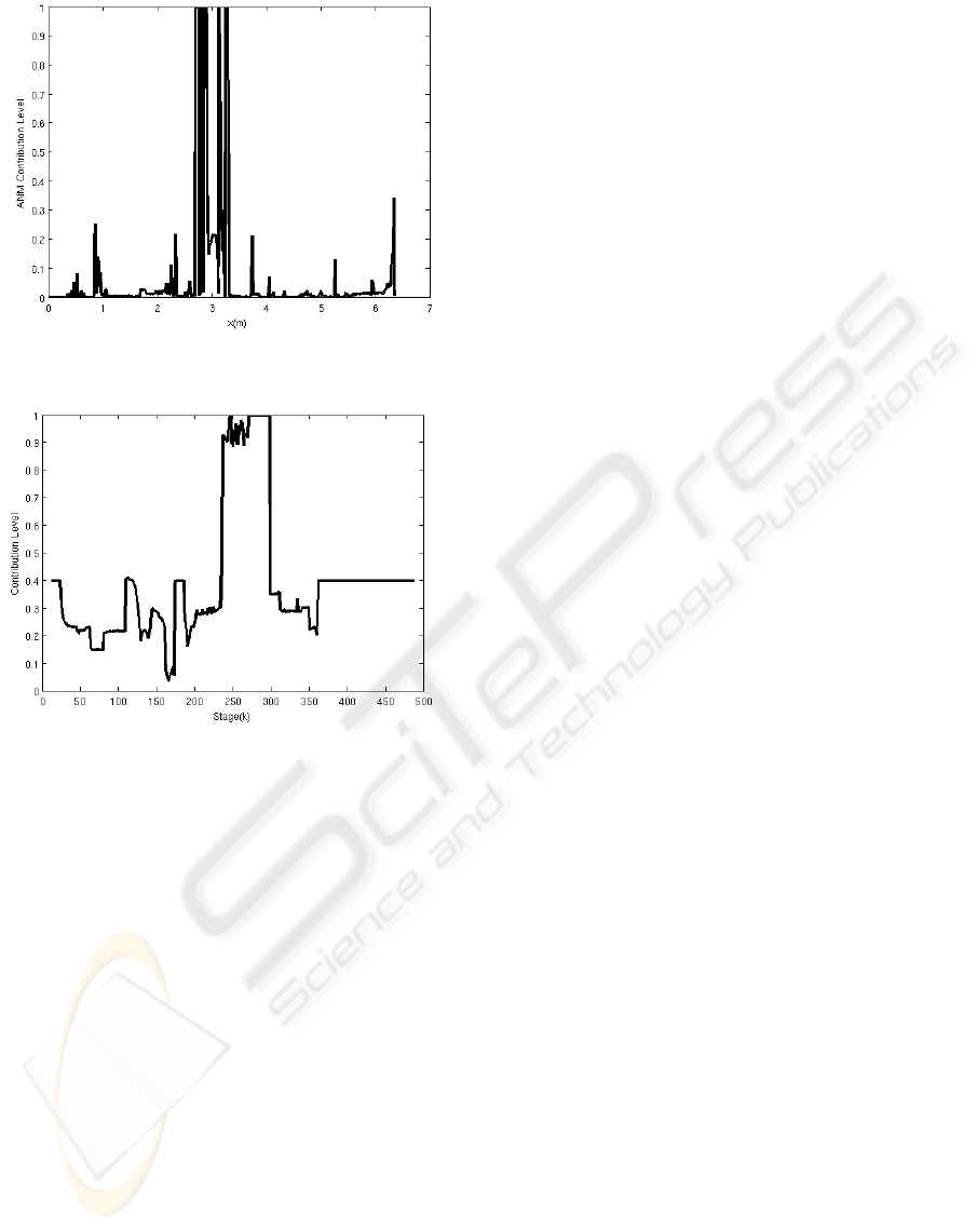
Figure 7: Collaborative Control: ANM Contribution Level
α while the platform is moving on the x − axis.
Figure 8: Dynamic Evolution of al pha during doorway
traversing experiment.
5 CONCLUSIONS
A robotic architecture that allows a human agent and
an autonomous navigation module agent to collabo-
rate during navigation tasks was proposed. This ar-
chitecture has three layers, namely deliberative, se-
quencing and execution layers. In order to build the
deliberative layer, an arbritage scheme based upon
the value of a non-collision index is used. In the se-
quencer layer, both agents control signals are taken
into account. Experiments performed with a mobile
platform show that this architecture and its arbitration
scheme can be used in robotic application in order to
enhance a human agent obstacle avoidance capabil-
ity. Applications such as powered wheelchair driving
could use the proposed architecture.
ACKNOWLEDGEMENTS
This work has been supported by the Natural Science
and Engineering Research Council of Canada (Grant
No CRD 349481-06 and Scholarship No BESC D3-
348674-2007). The authors wish to tank Hai Nguyen,
Vincent Zalzal, Raphael Gava and Alexandre Fortin
from the Perception and Robotics Laboratory of Ecole
Polytechnique for their contributions in implementa-
tion and testing.
REFERENCES
A. Huntemann, E. D. and al. (2007). Bayesian plan recog-
nition and shared control under uncertainty: Assist-
ing wheelchair drivers by tracking fine motion paths.
In International Conference on Intelligent Robots and
Systems. San Diego, CA, United States.
Astolfi, A. (1999). Exponential stabilization of a wheeled
mobile robot via discontinuous control. In Journal of
Dynamic Systems, Measurement, and Control.
Borenstein, J. and Koren, Y. (1991). The vector field
histogram-fast obstacle avoidance for mobilerobots.
In IEEE Transactions on Robotics and Automation.
Brooks, R. A. (1986). A robust layered control system for
a mobile robot. In IEEE Journal on Robotics and Au-
tomation.
C. Urdiales, A. Poncela, I. S.-T. F. G. M. O. and Sandoval,
F. (2007). Efficiency based reactive shared control
for collaborative human/robot navigation. In Interna-
tional Conference on Intelligent Robots and Systems.
San Diego, CA, USA.
Cruz, J. B. (1978). Leader-follower strategies for multilevel
systems. In IEEE Transactions on Automatic Control.
E. Gat, R. P. B. and Murphy, R. (1998). On three-layer
architectures. In Artificial Intelligence and Mobile
Robots.
H. J. Toby, C. and al. (2005). Player 2.0: Toward a practical
robot programming framework,. In Australasian Con-
ference on Robotics and Automation. Sydney, Aus-
tralia.
Lewis, F. and Syrmos, V. (2005). Optimal control. New
York, John Willey & Son.
Q. Zeng, B. Rebsamen, E. B.-L. C. (2008). A collaborative
wheelchair system. In IEEE Transactions on Neural
Systems and Rehabilitation Engineering.
S. Belkhous, A. Azzouzi, M. S.-C. N. and Nerguizian, V.
(2005). A novel approach for mobile robot naviga-
tion with dynamic obstacles avoidance. In Journal of
Intelligent and Robotic Systems.
S. Katsura, K. O. (2004). Human collaborative wheelchair
for haptic interaction based on dual compliance con-
trol. In IEEE Transactions on Industrial Electronics.
Simaan, M. and Cruz, J. B. (1973). On the stackelberg strat-
egy in nonzero-sum games. In Journal of Optimiza-
tion Theory and Applications.
HEALTHINF 2010 - International Conference on Health Informatics
322

Skrzypczyk, K. (2005). Control of a team of mobile robots
based on non-ccoperative equilibra with partial co-
ordination. In International Journal Applied Mathe-
matic Computer Science.
T. Okawa, E. S. and Yamaguchi, T. (2007). Information sup-
port system with case-based reasoning using motion
recognition in human-centered city. In SICE Annual
Conference. Takamatsu, Japan.
T. Taha, J. M. and Dissanayake, G. (2007). Wheelchair
driver assistance and intention prediction using
pomdps. In International Conference on Intelligent
Sensors, Sensor Networks and Information Process-
ing. Melbourne, VIC, Australia.
Y. C. Ho, P. L. and Olsder, G. (1982). Control-theoretic
view on incentives. In Automatica.
Y. Kanayama, K. Yoshihiko, F. M. and Noguchi, T. (1990).
A stable tracking control method for an autonomous
mobile robot. In IEEE International Conference
Robotics and Automation.
Y. Qi, Z. W. and Huang, Y. (2008). A non-contact eye-
gaze tracking system for human computer interaction.
In International Conference on Wavelet Analysis and
Pattern Recognition. Beijing, China.
Zalzal, V. and al. (2006). Mutual localization of mobile
robotic platforms using kalman filtering. In IEEE In-
dustrial Electronics Conference.
ARCHITECTURE FOR HUMAN-ROBOT COLLABORATIVE NAVIGATION
323
