
INTEGRATION OF SMART USER INTERFACES IN THE
NAVIGATION SYSTEM OF POWERED WHEELCHAIRS
Cristina Carletti and Sauro Longhi
Dipartimento di Ingegneria Informatica, Gestionale e dell’Automazione
Universit´a Politecnica delle Marche, via Brecce Bianche, 60131 Ancona, Italy
Keywords:
Smart wheelchair, Rehabilitation robotics, Navigation system, Shared-control, Human machine interface.
Abstract:
This paper presents a navigation system that extends the use of Electric Powered Wheelchairs (EPWs) to
people with upper limbs impairments that prevent them the control of a traditional joystick-driven EPW. To
achieve this aim, an Automatic Speech Recognition (ASR) system and a Brain Computer Interface (BCI)
have been introduced to enable the user to asynchronously perform and send the control commands to the
navigation module, according to her/his limited residual capabilities. Moreover, a shared-control algorithm
has been developed to translate the user’s guidance wishes into directions of motion that maximize the security
and minimize the physical and cognitive effort for the user. A preliminary analysis of the proposed navigation
system showed satisfactory results in terms of security and fulfillment of the user wishes.
1 INTRODUCTION
The loss of mobility for an individual represents one
of the most severe obstacles for an independent life.
The Electric Powered Wheelchair (EPW) is an ef-
fective tool to augment the autonomy of people with
lower limbs impairments. Nevertheless, these devices
are useless for subjects who do not have a sufficient
control of the upper limbs. In the last decade a large
number of research teams focused on how to extend
the use of EPWs to these users.
Two aspects of the problem can be considered.
The first one regards the integration of commercial
wheelchairs with certain levels of intelligence and au-
tonomy to allow an easy, comfortable and safe nav-
igation, at least in an indoor environment. The ”in-
telligence” of the wheelchair is based on its capacity
to perceive its surroundings thanks to various sensors
such as ultrasonic or vision sensors. With these in-
formation the wheelchair can generate autonomous or
semi-autonomous motions (i.e. obstacle avoidance,
wall following) (G.Bourhis and Sahnoun, 2007).
The second aspect concerns the availability of Human
Machine Interfaces (HMIs) to enable the guidance of
an EPW in an asynchronous way without the use of
the upper limbs.
Regarding the first aim, significant research activities
have been developed, see, e.g. the VAHM project
(Bourhis and Pino, 1996), the NavChair assistive
wheelchair navigation system (Levine et al., 1999),
(Simpson and Levine, 1999), the Hephaestus smart
wheelchair (Simpson et al., 1999). These works pro-
vided commercially available EPWs with different
levels of autonomy to perform a safe navigation keep-
ing the user in the control loop. In all the above
smart wheelchairs autonomy and security aspects are
guaranteed by a set of sonar sensors. Different sen-
sor devices, such as vision systems, are also used
in the Wheelesley (Yanco, 1998), (Yanco and Gips,
1997) and TAO (T.Gomi and Griffith, 1998) intelli-
gent wheelchairs.
Regarding the HMIs, many research activities in the
field of Rehabilitation Engineering are involved to the
development of new augmentative communication
and control technology for people with severe dis-
abilities. Several solutions to replace a joystick-based
control of an EPW have been proposed. These involve
eye tracking systems (C.S.Lin et al., 2006), head ges-
ture analyzers (Hu et al., 2007), Automatic Speech
Recognition systems (ASRs)(Simpson and Levine,
2002), Brain Computer Interfaces (BCIs) (Mill´an,
2008). An ASR interface translates vocal words into
commands for the control of the device. Therefore,
it can be used even by quadriplegic subjects with a
121
Carletti C. and Longhi S. (2010).
INTEGRATION OF SMART USER INTERFACES IN THE NAVIGATION SYSTEM OF POWERED WHEELCHAIRS.
In Proceedings of the Third International Conference on Biomedical Electronics and Devices, pages 121-126
DOI: 10.5220/0002749301210126
Copyright
c
SciTePress
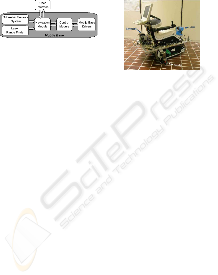
Figure 1: The architecture of the Navigation System.
residual capability of pronouncing a limited set of
words. Unfortunately, voice control has proven dif-
ficult to implement within a standard EPW. The main
difficulties are the wrong recognition of the user’s
voice, the limited rate by which information can be
transmitted by voice, the reduced vocabulary and so
the reduced set of available guidance commands.
A BCI enables the communication between an in-
dividual and a computer through a conscious and
spontaneous modulation of the brainwaves (Mill´an
et al., 2004). It provides the user with new com-
munication and control ways that do not depend on
the brain’s normal output channels such as periph-
eral nerves and muscles (Wolpaw et al., 2002). After
a training period, even a completely paralyzed per-
son can write messages using a virtual keyboard on a
computer screen, browse the internet, operate simple
computer games and move a cursor. However, cur-
rent ElectroEncephaloGraph(EEG)-based BCIs are
not suitable for complex applications, i.e. controlling
a neuroprosthesis or driving an EPW, due to low infor-
mation transfer rates (Mill´an, 2008). In this context,
good results have been obtained using synchronous
P300-based BCIs (Iturrate et al., 2009), (Blatt et al.,
2008). The problem is harder when an asynchronous
motor imagery-based BCI is used because a very
small set of guidance commands is allowable. How-
ever, it has been shown that online EEG signal analy-
sis is sufficient for humans to continuously control a
wheelchair, if combined with advanced robotics and
machine learning techniques (Mill´an et al., 2004).
The proposed navigation module implements a
shared-control algorithm which enables a safe guid-
ance with a reduced set of commands and with a low
transfer-rate. These features allow the integration in
the navigation system of usable HMIs like an ASR
and a BCI.
The paper is organized as follows. Section 2 de-
scribes the navigation system while the Section 3 in-
troduces the main features of the human-computer in-
terfaces integrated in it. The experimental and simu-
lation tests are discussed in Section 4.
Figure 2: TGR-Explorer with data acquisition system.
2 NAVIGATION SYSTEM
2.1 Architecture
The architecture of the proposed navigation system
is represented in Figure 1. The mobile base is the
TGR-Explorer (http://www.tgr.it), a joystick-driven
wheelchair successively equipped with a 100MHz
486-based computer and a sensor system (Figure 2).
Two incremental optical encoders aligned with the
axes of the driving wheels and a fiber optic gyro-
scope, mounted on the back of the vehicle compose
the dead-reckoning system. A laser range finder is
also present, for detecting obstacles in the surround-
ing environment. Data acquired by the sensor system
and the user command sent by the user interface mod-
ule are received by the navigation module and elabo-
rated in order to compute an obstacle-free direction of
movement. Finally, the control module translates the
control variables into low level instructions for the ac-
tuators of the driving wheels.
2.2 Map Building
A real time map building algorithm has been devel-
oped. It is based on the Histogramic In-Motion Map-
ping (HIMM) and modified to work with the laser
sensor instead of the traditional ring of ultrasonic sen-
sors. Following this approach, the environment is rep-
resented through a two-dimensional Histogram Grid.
Each cell of the grid is associated with a Certainty
Value (CV) which represents the confidence in the ex-
istence of an obstacle at that location. The map is con-
tinuously updated by new sensor data while the robot
is moving. To reduce the computational cost, the map
updating involves only a reduced area (Active Region)
inside the measure range of the laser. This area is a
BIODEVICES 2010 - International Conference on Biomedical Electronics and Devices
122
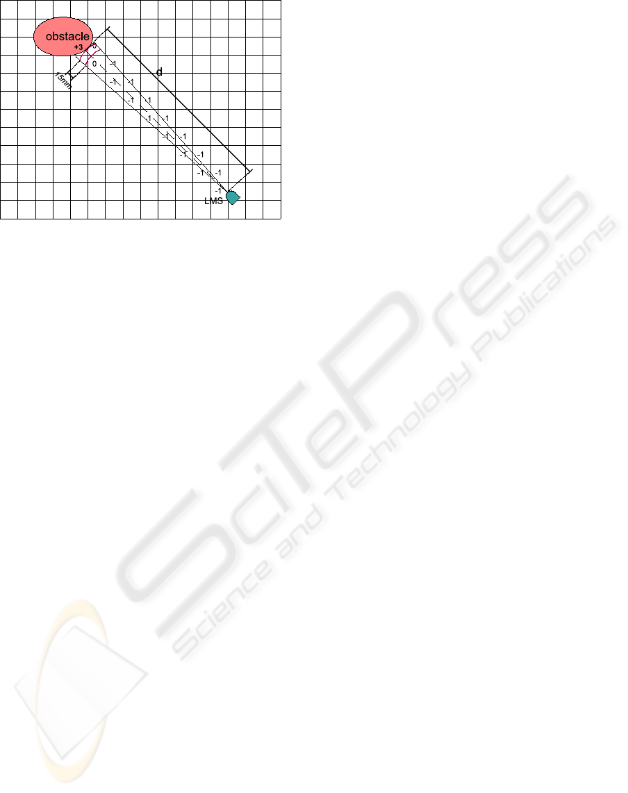
Figure 3: Histogramic Grid Update using a Laser Measure-
ment System (LSM).
semicircle of radius 3m centered at the actual posi-
tion of the laser. Moreover, inside the Active Region,
only the CV of the cells lying on the actual reading
axis of the sensor are updated. In particular, the CV
of the cell corresponding to the measured distance d
(d < 3m) is incremented, while the CV of the all cells
lying between the obstacle and the sensor (along the
central axis of the actual measure cone) is decreased.
As the measure cone of the laser is continuously and
rapidly sampled, a histogramic probability distribu-
tion is obtained, in which high CVs are associated
with cells close to the actual location of the obstacle.
Limiting the CV update to the cells along the central
axis of each measure cone, the HIMM procedure al-
lows a fast map-building that can be used for real-time
applications, i.e. real-time obstacle-avoidance proce-
dures.
Considering a laser scan angle equal to 180deg and a
sensor resolution of 1deg, we can assume to have 181
measure cones, much more than the typical number
of sensors composing a sonar system (16 or 24 typ-
ically). Moreover, as the amplitude of the light spot
is about 0.25deg, the measure cones are very narrow
comparing to the sonar ones, typically of 30deg. Con-
sequently, every measure cone can be approximate
with a line, corresponding to its central axis. The CV
range has been chosen varying from 0 to 15 and its
initial value has been fixed as 7 for all cells in the
grid. It means that until the robot has no information
about the external environment, all the cells have the
same probability to be empty or occupied. As laser
data arrive, the CV of the cell corresponding to the
measure is increased by I
+
= +3 while the CVs of
the cells lying along the reading axis are decreased by
I
−
= −1. Finally, the CV of the cells adjacent to the
increased one are not modified. The reason is that the
maximum measure error for the laser is smaller than
15mm and the cell side is 50mm. Consequently, the
largest measure error could affect only the CV of the
neighboring cells. A schematic representation of this
procedure is shown in Figure 3. According to the ex-
perimental results, occupied cells do not significantly
spread out during the robot movements in the pres-
ence of obstacles. This can be explained by the large
number of measurements available and the accuracy
of the laser. Moreover, due to the high angular res-
olution, the saturation of cells’ CV is reached in few
steps. The result is a very detailed map, as will be
described in the Section 4 and by the Figure 4.
2.3 The Autonomy Levels of the
Navigation Module
The definition of the right level of autonomy for a
navigation system is a critical aspect when the user
is within the control loop. A higher level of auton-
omy helps to reduce the user guidance effort and re-
quires a lower guidance skill. However, it bounds the
user control capability, leading to the feeling of losing
the vehicle control. Therefore, the right tradeoff be-
tween autonomy and control power is very important
for the acceptance of the system by the user and for
the adaptation to her/him residual capabilities. For
this reason, two levels of intelligence and autonomy
are developed.
In the first one, the navigation module performs a sim-
ple filtering of the user commands: if an obstacle is
detected inside a certain “security area”, the module
starts the Stop procedure decreasing the vehicle’s ve-
locity. If the system receives a new user command,
the feasibility of the new motion direction is evalu-
ated and, in case of positive result, the new command
is executed. Otherwise the vehicle is stopped until
a new user command arrives. The “security area” is
a cone-shaped portion of the environment in front of
the robot with opportunity dimensions to guarantee
the stop of the vehicle whatever manoeuvre it is exe-
cuting .
In the second level of autonomy, a VHF-based obsta-
cle avoidance algorithm (Bell et al., 1994) introduces
some local corrections on the user commands. If the
obstacle is detected inside the security area, a correc-
tion on the velocity and on the steering angle is au-
tomatically introduced. This correction is computed
considering the relative position of the detected ob-
stacle and the last user command.
INTEGRATION OF SMART USER INTERFACES IN THE NAVIGATION SYSTEM OF POWERED WHEELCHAIRS
123

3 HUMAN MACHINE
INTERFACE
The aim of the navigation system is to extend the use
of EPWs to people with severe upper limbs impair-
ments and even to those completely paralyzed. To
reach this goal, two human-machine interfaces are
considered: an Automatic Speech Recognition (ASP)
device and a Brain Computer Interface (BCI).
3.1 Automatic Speech Recognition
An automatic speech recognition (ASR) converts
acoustic signals emitted by an individual, into digi-
tal signals available for a computer.
ASR can be very helpful for users with disabil-
ities that preserve them for using a keyboard, a
mouse or a joystick. Unfortunately, voice control has
proven difficult to implement within a standard power
wheelchair. The main difficulties concern with the
wrong recognition of the user’s voice, the limited rate
by which information can be transmitted by voice,
the reduced vocabulary and so the reduced set of
available guidance commands (Simpson and Levine,
2002). Moreover, the pronunciation of the same word
can change from user to user and even for the same
user in different time instants and/or operative condi-
tions.
In the developed ARS module, that has been inte-
grated with the navigation module, a reduced set of
guidance commands has been introduced and a low
transfer rate has been used. Specifically, only four
commands are available: they are “go forward”, “turn
right”, “turn left” and “stop”, associated to the words
“forward”, “right”, “left” and “stop” respectively. The
reversemotion is not implemented because no sensors
are present in the rear side of the vehicle.
The considered transfer rate is 0.5bit/sec. This chan-
nel capacity has been chosen according to the previ-
ous explanation and to the features of the BCI, as de-
scribed in the next subsection.
3.2 Brain Computer Interface
The Brain Computer Interface (BCI) provides user
with communication and control channels that do not
depend on the brains normal output channels such as
peripheral nerves and muscles (Wolpaw et al., 2002).
The device analyzes brain waves in order to deter-
mine the subjects’ mental task. The recognized men-
tal task is then mapped into actions such as commands
to move a mobile base. Different BCI implementa-
tions exist and they are differentiated with respect to:
the technique by which the brain waves are acquired
(invasive or non-invasive BCIs), the variety of brain-
wave phenomena considered (synchronous or asyn-
chronous protocols) and the classification algorithms
developed (Lotte et al., 2007)
An EEG-based BCI is here considered. In an EEG-
based BCI, the brain electrophysiological signals are
recorded by electrodes on the user skin by a classical
EEG. These raw signals are first processed in order to
extract some relevant features and then sent to a clas-
sification algorithm. This component allows to dis-
criminate which mental task the subject is performing
and associate it to a command for the external device.
Finally, a visual or acoustic or haptic feedback in-
forms the user about the mobile base’s state or the task
that it is about to be execute. The design of the present
navigation system takes into account a MAIA-like
BCI (MAIA: Mental Augmentation through Determi-
nation of Intended Action). In the following the prin-
cipal features are recalled (Mill´an et al., 2004).
• It is an asynchronous BCI based on the motor im-
agery. This means that the subject can issue com-
mands for the guidance of the vehicle at any mo-
ment and without waiting for the synchronization
with external cues.
• It is portable (only 8 electrodes are required for
the brain signals acquisition) and so it can be car-
ried on the mobile base.
• The statistical classifier is able to discriminate
three mental tasks. The tasks are getting re-
laxed, imaging repetitive self-paced movements
of a limb, visualizing a spinning cube, perform-
ing successive elementary subtractions by a fixed
number (e.g., 64− 3 = 61, 61− 3 = 58, etc.), and
concatenating related words. Among these tasks,
after an initial training period, the subject chooses
to work with the three mental tasks that s/he can
execute more easily.
• The bit rate is about 0.5bit/sec. By assuming to
digitalize each of the three commands with two
bits, only one command every 4sec is possible.
The navigation system provide the wheelchair
with the intelligence necessary to make up for the
lack of control due to the low channel capacity.
3.3 User Feedback
A video display is used to provide the user a visual
feedback. It is made of three different arrows corre-
sponding to the three possible directions of motion for
the mobile base. When the navigation system receives
the user command, the corresponding arrow is lighted
on the screen. This procedure gives a visual feedback
to the user about the command computation. More-
BIODEVICES 2010 - International Conference on Biomedical Electronics and Devices
124
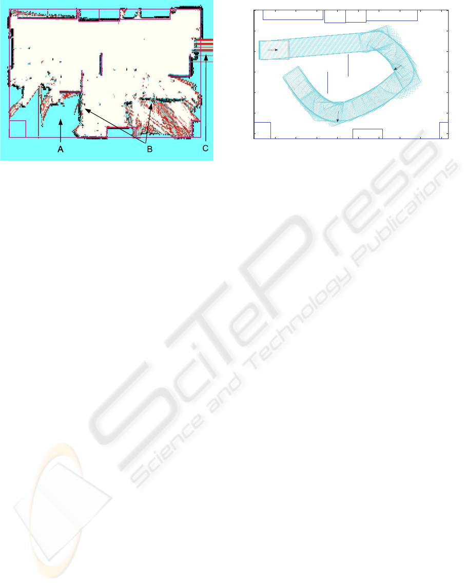
Figure 4: Map built by laser range finder readings at the
end of the experimental test in an indoor environment. The
black lines represent real obstacles.
over, a flashing arrow represents the movement that
the mobile base is executing. If an obstacle goes into
the security area and the previous movement sent by
the user becomes unsafe, the navigation system au-
tomatically changes the vehicle direction to a safer
one. In this case the flashing arrow and the lighted
one will be different. This feedback allows the user
to distinguish between an error in the computation of
the command or to a safer manoeuvre performed by
the security module.
4 OPERATION DETAILS AND
EXPERIMENTAL RESULTS
Experimental tests with the TGR-Explorer were car-
ried out to evaluate the map building algorithm. Fig-
ure 4 represents a 9.33m x 6.25m room (straight ma-
genta/dark grey lines) and a laser map with squared
cells of 50mm x 50mm. The cyan/light grey regions
correspond to unexplored areas (A), holding a CV
equal to 7; the white parts correspond to empty cells,
which have a CV of 0; the black cells have a CV equal
to 15 and so they havea very high probability to be oc-
cupied. It can be noticed that all the obstacles reached
by the laser beam results modeled with high precision
also if they are not present in the a priori map (B).
Measure errors due to multiple light reflections into
narrow areas can be also noticed (C). The result is a
very detailed map.
Preliminary simulation tests have been performed
in order to evaluate the proposed navigation system.
Different obstacle configurations reproducing typical
domestic environments have been considered. In both
levels of autonomy, the angular width and the length
of the security area are 180deg and 3m, respectively.
0 1000 2000 3000 4000 5000 6000 7000 8000 9000
0
1000
2000
3000
4000
5000
6000
Right
Forward
Left
Figure 5: Simulation test in an environment crowded with
obstacles. The path performed by the wheelchair with the
second level of autonomy is depicted (clockwise direction
of motion). The arrows represent the directions chosen by
the user in the corresponding instant. The (blue) straight
lines reproduce the obstacles. The values are in millimeters.
Regarding the first level, the navigation module acti-
vates the Stop procedure when an obstacle is detected
in the security area. If the user imposes a safe avoid-
ance manoeuvre before the Stop procedure is finished,
the navigation module does not stop the vehicle and
continues executing the user command.
At the second level of autonomy, the navigation mod-
ule introduces some corrections on the user com-
mands. A modified version of the obstacle avoidance
algorithm proposed in (Bell et al., 1994) was devel-
oped taking into account the limited set of guidance
commands and the low channel capacity, as described
in section 3. When an obstacle is detected in the se-
curity area, a correction on the steering angle is made
until the security area is free of obstacles and the
wheelchair speed is reduced using a linear function
of the imposed correction. In the Figure 5 a signifi-
cant test is presented. The dotted line represents the
trajectory performed by the wheelchair with the sec-
ond level of autonomy as imposed by the navigation
module. The arrows represent the directions chosen
by the user. It can be noted that the navigation system
executes the user command only if this is safe, i.e. for
the Right command in the Figure 5. If the user com-
mands result unsafe, the navigation system introduces
corrections to them in order to guarantee a better se-
curity level for the vehicle, i.e. in the case of Forward
command at the beginning of the navigation and of
Left command in the second part of the navigation as
showed in the same Figure 5. The navigation module
maintains trajectory of the mobile base sufficiently far
from the wall and from all the obstacles.
INTEGRATION OF SMART USER INTERFACES IN THE NAVIGATION SYSTEM OF POWERED WHEELCHAIRS
125

5 CONCLUSIONS AND FUTURE
WORK
This paper describes a navigation system to extend
the use of commercial powered wheelchairs to people
with severe upper limbs disabilities.
Two user interfaces have been integrated into the re-
habilitation device, an Automatic Speech Recognition
program and a Brain Computer Interface, providing
the user with new useful channels for communication
and control.
A map building algorithm has been developedto work
with a laser range finder sensor. Experimental tests
performed in indoor environments have shown that
the algorithm is able to build in real-time a very de-
tailed map of the explored environment.
Different levels of autonomy for the navigation mod-
ule of the wheelchair have been developed taking into
account the limited set of commands and the low
channel transfer rate of the chosen interfaces. Pre-
liminary simulation tests of the developed navigation
procedure have shown that it is reliable and satisfac-
tory in terms of security and fulfillment of the user
wishes. The design of the navigation module has been
done by a modular architecture so that the adaptation
of the navigation system to different commercial pow-
ered wheelchairs should not be too expensive. It is
necessary to adapt just two modules: the control mod-
ule of the power electronics of the wheelchair elec-
tric drivers, and the guidance module of the obstacle
avoidance algorithm.
The analysis of the developed simulation tests has
specified the necessity of some technological im-
provements. Information about the environmentclose
to the lateral sides of the robot, not possible for the
frontal laser, could be useful to limit the manoeuvre
space and/or to enhance the security.
Moreover, an adaptive module could be introduced to
let the navigation closer to the user’s wishes.
These technical and methodological improvements
will be developed in further research activities in or-
der to improve the performance of the developed nav-
igation module in different indoor environments.
REFERENCES
Bell, D., Levine, S., Koren, Y., Jaros, L., and Borenstein,
J. (1994). Design criteria for obstacle avoidance in
a shared-control system. Proceedings of the RESNA
International Conference, pages 581–583.
Blatt, R., Ceriani, S., Seno, B. D., Fontana, G., Matteucci,
M., and Migliore, D. (2008). Brain control of a smart
wheelchair. Proceedings of the International Confer-
ence on Intelligent Autonomous System.
Bourhis, G. and Pino, P. (1996). Mobile robotics and mobil-
ity assistance for people with motor impairments: ra-
tional justification for the vahm project. IEEE Trans-
actions on Rehabilitation Engineering, 4(1):7–12.
C.S.Lin, C.W.Ho, Chen, W., Chiu, C., and Yeh, M. (2006).
Powered wheelchair controlled by eye-tracking sys-
tem. Optica Applicata, 36(2-3):401–412.
G.Bourhis and Sahnoun, M. (2007). Assisted control mode
for a smart wheelchair. Proceedings of the Interna-
tional Conference on Rehabilitation Robotics.
Hu, H., Jia, P., Lu, T., and Yuan, K. (2007). Head ges-
ture recognition for hands-free control of an intelli-
gent wheelchair. Industrial Robot: An International
Journal, 34(1):60–68.
Iturrate, I., J.Antelis, Minguez, J., and A.Kubler (2009).
Non-invasive brain-actuated wheelchair based on a
p300 neurophysiological protocol and automated nav-
igation. IEEE Transactions on Robotics.
Levine, S. P., Bell, D. A., Jaros, L. A., Simpson, R. C., Ko-
ren, Y., and Borenstein, J. (1999). The navchair assis-
tive wheelchair navigation system. IEEE Transactions
on Rehabilitation Engineering, 7(4):443–451.
Lotte, F., Congedo, M., Lcuyer, A., Lamarche, F., and Ar-
naldi, B. (2007). A review of classification algorithms
for eeg-based brain-computer interfaces. Journal of
Neural Engineering, 5(2):R1–R13.
Mill´an, J. (2008). Brain-controlled robots. IEEE Intelligent
Systems, 23:7476.
Mill´an, J., Renkensb, F., Mourioc, J., and Gerstnerb, W.
(2004). Non-invasive brain-actuated control of a mo-
bile robot by human eeg. IEEE Transactions on
Biomedical Engineering, 51(6):1026–1033.
Simpson, R. and Levine, S. (2002). Voice control of a pow-
ered wheelchair. IEEE Transactions on Neural Sys-
tems and Rehabilitation Engineering, 10(2):122–125.
Simpson, R., Poirot, D., and Baxter, M. F. (1999). Evalua-
tion of the hephaestus smart wheelchair system. Pro-
ceedings of the International Conference on Rehabili-
tation Robotics, ICORR’99, pages 99–105.
Simpson, R. C. and Levine, S. P. (1999). Automatic adap-
tation in the navchair assistive wheelchair navigation
system. IEEE Transactions on Rehabilitation Engi-
neering, 7(4):452–463.
T.Gomi and Griffith, A. (1998). Developing intelligent
wheelchairs for the handicapped. Assistive Technol-
ogy and Artificial Intelligence, 1458:151–178.
Wolpaw, J., Birbaumer, N., McFarland, D., Pfurtscheller,
G., and Vaughan, T. (2002). Brain-computer inter-
faces for communication and control. Clinical Neuro-
physiology, 113:767–791.
Yanco, H. (1998). Wheelesley: A robotic wheelchair sys-
tem: Indoor navigation and user interface. Assistive
Technology and Artificial Intelligence, 1458:256–268.
Yanco, H. and Gips, J. (1997). Preliminary investiga-
tion of a semi-autonomous robotic wheelchair direct
through electrodes. Proced. of the Rehabilitation En-
gineering Society of North America Annual Confer-
ence, RESNA Press:141–146.
BIODEVICES 2010 - International Conference on Biomedical Electronics and Devices
126
