
BIOREACTOR FOR MECHANICAL CELL STIMULATION
Concept and Design
J. G. Rocha, V. Correia
Industrial Electronics Dept., University of Minho, Campus de Azurem, 4800-076 Guimaraes, Portugal
J. L. Gomez Ribelles
Centro de Biomateriales, Universidad Politécnica de Valencia, 46022, Valencia, Spain.
Regenerative Medicine Unit, Centro de Investigación Príncipe Felipe, Autopista del Saler 16, 46013 Valencia, Spain
CIBER en Bioingeniería, Biomateriales y Nanomedicina, Valencia, Spain.
S. Lanceros-Mendez, A. Pitaes
Physics Dept., University of Minho, Campus de Gualtar, 4700-058 Braga, Portugal
Keywords: Bioreactor control, Cell cultivation, Three-dimensional scaffold.
Abstract: Mechanical stimulation plays an important role in improving cell growth in the skeletal system, for
example. In this article we describe a bioreactor in which cells in a three-dimensional scaffolds are
stimulated by cyclically applied mechanical loads. The objective of this study is to develop a custom-
designed bioreactor capable of applying controlled compressive loads to a cell-encapsulating scaffold. Its
working principle is based on an innovative design of a feedback controlled electromagnetic actuator, which
allows the application of compressive forces to the samples and at the same time, it allows the measurement
of the produced displacement.
1 INTRODUCTION
In vivo, skeletal cells such as osteoblasts and
chondrocytes are subjected to mechanical
stimulation imposed by muscle contraction and body
movement (lee, 2009). It has been demonstrated
mechanical stimuli play a role in improving cell
growth in the skeletal system (Nugent-Derfus,
2007), (Kisidaya, 2004), (Cooper, 2007), (Garvin,
2003). Many research groups have developed
bioreactors to stimulate cell-seeded, three-
dimensional scaffolds. The mechanical environment
influences tissue growth and development. The
proper mechanical force that can produce correct
bone tissue is a key issue in order to being able to
develop bone tissue in vitro. Static constant
mechanical loads have little or no effect in cell
growth and proliferation, but cyclically applied loads
do have profound effects (Meyer, 2001) (Guldberg,
2002).
Several models of bioreactors have been
developed for the stimulation of three-dimensional
scaffolds of bone and cartilage (Godstein, 2001),
(Botchwey, 2001), (Hillsley, 1994). All of these
bioreactors are satisfactory for the growth of tissues
but do not include the possibility of applying cyclic
loads that might be important in the case of skeletal
cells.
The main goal of this work is to develop and test
a bioreactor in which cells in three-dimensional
scaffolds are stimulated by cyclically applied
mechanical loads. The objective of this study was to
develop a custom-designed bioreactor capable of
applying controlled compressive loads to a cell-
encapsulating scaffold.
2 BIOREACTOR DESCRIPTION
Figure 1 shows a drawing of the mechanical
actuation system of the bioreactor. It is composed by
an iron core, where four coils are placed. Two of the
coils will produce magnetic fields that displace the
147
Rocha J., Correia V., Gomez Ribelles J., Lanceros-Mendez S. and Pitaes A. (2010).
BIOREACTOR FOR MECHANICAL CELL STIMULATION - Concept and Design.
In Proceedings of the Third International Conference on Biomedical Electronics and Devices, pages 147-151
DOI: 10.5220/0002759401470151
Copyright
c
SciTePress
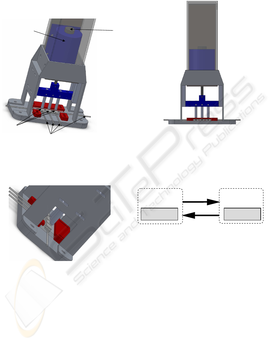
core, while the other two work as sensors to
feedback the core position to the controller.
Figure 1: Bioreactor design.
Figure 2 shows a detail of the bioreactor, where the
compression and circulation systems are seen in
detail.
Figure 2: Detail of the actuation system of the bioreactor.
Figure 3 shows the front-view of the bioreactor
actuating system.
3 CONTROL ELECTRONICS
The general system architecture is a master-slave
structure since there are two control units: a high-
level one (master) and a low-level one (slave).
The high-level control unit, central processing
unit or simply the master is responsible for
supporting the user interface, exchanging and
processing the necessary information between the
user and The low-level control unit and storing the
Figure 3: Bioreactor actuation system front view.
measurement data. It is based on a computer (PC).
The low-level control unit or slave main component
is a microcontroller. It is responsible for acquiring
the data from the sensor and controlling the stress
applied to the samples under test.
Figure 4 shows the system architecture.
Figure 4: System architecture. The PC operates as master
and the microcontroller operates as a slave. The
microcontroller functionalities are programmed by the PC,
which receives the measured data.
3.1 Master Block
In order to obtain the optimal operation point, that is,
when the cellular growth approximates the one that
happen in the human body, it is necessary a generic
system able to change the operation parameters
during the experiments. In this way, in the proposed
system, the user is able to control the following
parameters:
- Initial date and time;
- Final date and time;
- Shape of the stimulus (on/off, sine wave,
pulse, ramp);
- Holding time;
- Active time;
- Displacement;
Sends actuation
parameters
Sends performance
Information
PC
Maste
r
Slave
Microcontrolle
r
Windings
Core
Biological fluid
circulation system
Compression
system
BIODEVICES 2010 - International Conference on Biomedical Electronics and Devices
148
- Oscillation amplitude and frequency;
- Number of oscillation cycles;
- Standing Time (to generate a sequence);
- Up time
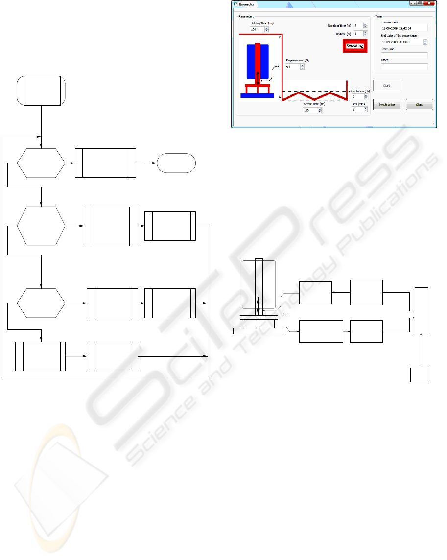
Figure 5 shows the flow chart of the master
algorithm.
Figure 5: Master control flow chart.
It consists in a main loop where three decisions must
be taken. The first one is related to the end of the
experiment. If it happens, the actuator must be
stopped, the user must be informed and the program
stops. The second one is related to the end of a hold
or active state. In this case, the new state parameters
must be loaded and sent to the slave block. The third
one is related with the oscillation of the actuator. If
the oscillation is not activated, its parameters must
be loaded and sent to the slave block. If the
oscillation is activated, the next deformation step
must be calculated and sent to the slave block.
Figure 6 shows a picture of the front panel of the
control application.
Figure 6: Front panel of the control application.
3.2 Slave Block
The Slave block is constituted by a microcontroller,
a power switching circuit based on a H-bridge, two
actuators (solenoids) and a measurement system
whose working principle is based on a LVDT
(Linear Variable Differential Transformer). Fig. 7
shows the block diagram of the whole system.
Figure 7: Control system of the mechanical movements of
the bioreactor.
The main goal of this system is to generate a set of
mechanical stimulus in a cellular cultivation region.
The microcontroller receives the desired stimulus
parameters from the computer and reads the actual
displacement of the actuator from the measurement
circuit. With that information, it calculates the duty-
cycle of the PWM and sends it to the power
switching circuit, in order to produce the correct
voltage to the actuator.
The displacement is the most important
parameter of the system, but the mechanical actuator
only allows the control of the mechanical stress
applied to the cultivation cell. In this way, the
control of the displacement is made in a feedback
loop, where a displacement sensing mechanism is
introduced.
Begin
End of
experiment?
y n
End of
hold/active
state?
y n
Is the
oscillation
activated?
Calculate
deformation
info
Stop actuator.
Informs the
user
Loading of
new state
parameters.
Jump to
new state
Loading of
oscillation
parameters
Send
deformation
info to
microcontrolle
r
Send state
info to
microcontroller
Send
oscillation
info to
microcontroller
Stop
y
n
Power
switching
circuit
Actuator
system
Measurement
system
Readout
circuit
PWM
position
info
Microcontroler
PC
USB
BIOREACTOR FOR MECHANICAL CELL STIMULATION - Concept and Design
149
The displacement actuator is then constituted by
four windings: two primary windings with a small
number of turns and two secondary windings with a
larger number of turns. The primary windings are
excited by the power switching circuit in order to
produce the displacement of the core. The secondary
windings use to advantage the switching frequency
of the PWM in order to measure the displacement,
as it will be described in the following paragraphs.
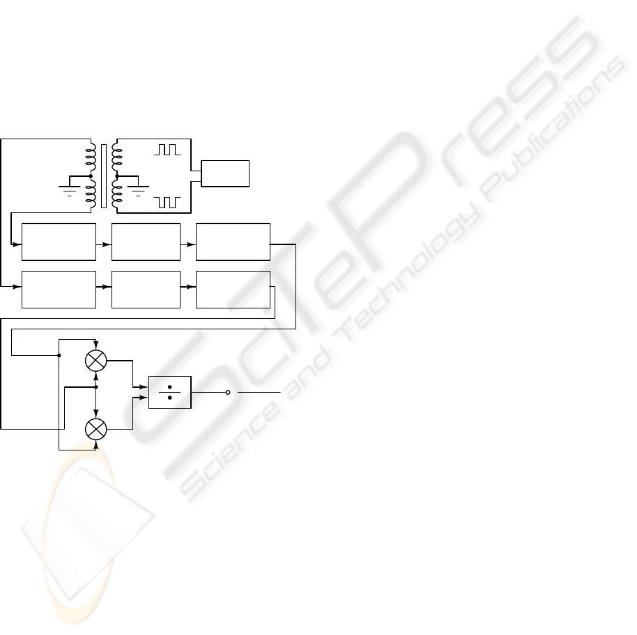
A block diagram of the displacement transducer
and respective signal conditioner is shown in Figure
8. The circuit consists of a PWM wave generator to
drive the primary windings, a conditioner circuit for
each secondary winding, a differential amplifier that
determines the difference between the voltages of
the secondary windings and a summing amplifier,
which determines the sum of the secondary winding
voltages.
Figure 8: block diagram of the displacement transducer
and signal conditioner.
The PWM wave that is applied to the primary
windings, where besides producing the displacement
of the core, it induces in the secondary windings a
voltage whose magnitude difference is proportional
to the core position. These two secondary voltages
are band-pass filtered for the fundamental frequency
of the PWM generator. So, the output from the band-
pass filters consists of a pair of sine waves whose
amplitude difference, (VA–VB), is proportional to
the core position.
In order to operate in a ratiometric principle and
thus eliminating the errors associated to non-
constant amplitude of the PWM signal, the circuit
computes (VA-VB)/(VA+VB).
The signals VA and VB are firstly rectified and
low-pass filtered. A signal with precise frequency is
not necessary because the inputs are rectified and
only the sine wave carrier magnitude is processed.
There is also no sensitivity to phase shifts between
the primary excitation and the secondary outputs
because synchronous detection is not employed.
Then, the signals are applied to the differential
amplifier and to the summing amplifier. The ratio
(VA-VB)/(VA+VB) is performed by the A/D
(analog to digital) converter. The (VA-VB) signal is
applied to its input and the (VA+VB) signal is used
as reference voltage for the A/D conversion. Finally,
The digital signal is read by the microcontroller.
4 CONCLUSIONS
In this article, it is described the design of a
bioreactor to apply controlled mechanical
stimulation to cell cultures. The bioreactor consists
on a mechanical loading actuator, experimental
chamber, and control system. The actuator is based
on an innovative design of a feedback controlled
electromagnetic actuator, which allows the
measurement of its own position. The control system
is based on a master-slave architecture, where the
master (computer) receives the user commands and
sends the actuation parameters to the slave
(microcontroller). This last one reads and feedback
controls the actuator position.
ACKNOWLEDGEMENTS
The authors thank the Portuguese Foundation for
Science and Technology (FCT) Grants
PTDC/CTM/73030/2006, PTDC/CTM/69362/2006
and NANO/NMed-SD/0156/2007. V. Correia thanks
the FCT for the PhD Grant (SFRH/BD/48708/2008).
J. L. G. Ribelles acknowledge the support of the
Spanish Ministry of Education through project No.
MAT2007-66759-C03-01 (including the FEDER
financial support. and founding in the Centro de
Investigación Principe Felipe in the field of
Regenerative Medicine through the collaboration
agreement from the Conselleria de Sanidad
(Generalitat Valenciana), and the Instituto de Salud.
+
+
-
+
VA-VB
VA+VB
VA
-VB
Full wave
Rectifier
Full wave
Rectifier
Low-pass
Filter
Low-pass
Filter
PWM
Band-pass
Filter
Band-pass
Filter
VA-VB
VA+VB
BIODEVICES 2010 - International Conference on Biomedical Electronics and Devices
150

REFERENCES
Lee, S.J., Jeong Hun Park, Yong-Joon Seol, In Hwan Lee,
Sang Soon Kang, Dong-Woo Cho, Development of a
bioreactor for the mechanical stimulation of agarose
hydrogels, Microelectronic Engineering 86 (2009)
1411-1415.
Nugent-Derfus G. E., Takara T., O’Neilly J. K., Cahill S.
B., Gortz S., Pong T., Inoue H., Aneloski N. M., Wang
W. W., Vega K. I., Klein T. J., Hsieh-Bonassera N. D.,
Bae W. C., Burke J. D., Bugbee W. D. and Sah R. L.,
Continuous passive motion applied to whole joints
stimulates chondrocyte biosynthesis of
PRG4,OsteoArthritis and Cartilage (2007) 15, 566-
574.
Kisidaya J. D., Jinb M., DiMiccod M. A., Kurze
B.,Grodzinsky A. J., Effects of dynamic compressive
loading on chondrocyte biosynthesis in self-
assembling peptide scaffolds, Journal of Biomechanics
37 (2004) 595-604.
Cooper Jr. J. A., Wan-Ju Li, LeeAnn O. Bailey, Steve D.
Hudson, Sheng Lin-Gibson, Kristi S. Anseth, Rocky
S. Tuan, Newell R. Washburn, Encapsulated
chondrocyte response in a pulsatile flow bioreactor,
Acta Biomaterialia 3 (2007) 13-21.
Garvin, J., Qi, J., Maloney, M., Banes, A.J., Novel System
for Engineering Bioartificial Tendons and Application
of Mechanical Load, Tissue Engineering Vol. 9 (5)
2003, 967-979.
Meyer U, Terodde M, Joos U, Wiesmann HP., Mechanical
stimulation of osteoblasts in cell culture, Mund Kiefer
Gesichtschir. 2001;5:166-72.
Guldberg RE., Consideration of mechanical factors, Ann
N Y Acad Sci 2002, 961, 312-314.
Godstein AS, Juarez TM, Helmke CD, Gustin MC, Mikos
AG. Effect of convection on osteoblastic cell growth
and function in biodegradable polymer foam scaffolds.
Biomaterials 2001, 22, 1279-1288.
Botchwey EA, Pollack SR, Levine EM, Laurencin CT.
Bone tissue engineering in a rotating bioreactor using
a microcarrier matrix system, J Biomed Mater Res
2001, 55, 242-253.
Hillsley MV, Frangos JA. Review: Bone tissue
engineering: the role of interstitial fluid flow,
Biotechnol Bioeng 1994, 43, 573-581.
BIOREACTOR FOR MECHANICAL CELL STIMULATION - Concept and Design
151
