
MIRA
CLE: A CAD/CAM SYSTEM FOR THE MANUFACTURE OF
DENTAL SURGICAL SPLINTS
Valery Naranjo, Roberto Llor
´
ens, Mariano Alca
˜
niz, Beatriz Rey, Salvador Albalat
∗
Instituto Interuniversitario de Investigaci
´
on en Bioingenier
´
ıa y Tecnolog
´
ıa Orientada al Ser Humano
Universidad Polit
´
ecnica de Valencia, Camino de Vera s/n, 46022 Valencia, Spain
Juan Fayos, I
˜
nigo Morales
Instituto de Biomec
´
anica de Valencia (IBV), Universidad Polit
´
ecnica de Valencia
Keywords:
Computer assisted dental surgery, Surgical splints.
Abstract:
Nowadays, design and manufacturing process of dental prostheses is very handmade, time consuming and
has a raised economic cost. Besides that, there is no objective methodology for the fulfillment of its func-
tional design specifications. This paper presents an overview of MIRACLE project whose objective is the
development and validation of an intelligent system for the design, simulation and flexible manufacture of
implant-supported dental prostheses. The developed system in MIRACLE is a CAD/CAM system which al-
lows to test the functional characteristics of dental prostheses considering mandible-maxilla interaction (called
occlusion) using virtual models, contrary to most commercial solutions where this test is performed using ex-
pensive anatomical replicas tested with mechanical articulators and evaluated with patients. Another objective
of MIRACLE is to develop a parametric finite elements model (FEM) of the whole prosthesis in order to an-
alyze the failure risk of dental implants and prostheses before its surgical implantation enabling a re-design
process. This paper is focused on the CAD/CAM subsystem developed in order to automatize the process of
manufacturing surgical guides using several 3D models of the patient dental anatomy. A summarized version
of the image processing step will be also presented. The CAD/CAM subsystem has been clinically validated
achieving mean errors less than 5 degrees in the placement of the prosthetic crowns.
1 INTRODUCTION
In an implant-supported prosthesis (PDI), the pros-
thesis is attached to an implant placed directly on the
mandibular or maxillary bone of the patient. The pro-
cess of a PDI implantation has been modified sub-
stantially in last years. Approximately five years ago
an implantation was made in two phases of the set
prosthesis-implants. In a first step, the implant was
placed and , after 3-6 months, when the osseointegra-
tion between implant and bone took place, the dental
prosthesis was placed. Nowadays the implant load
protocols are being modified in order to give the im-
plant a fundamentally masticatory function at the mo-
ment of their positioning or in the three following
days (”load or immediate function”).
∗
This
work has been supported by the project MIRA-
CLE (DPI2007-66782-C03-01-AR07) of Spanish Ministe-
rio de Educaci
´
on y Ciencia.
1.1 State of the Art of
Implant-supported Prosthesis
First antecedents of immediate load were given by
Ledermann (Ledermann, 1979). He placed an over-
denture on 4 implants between the dental foram-
inae in the same day of the surgery. Later on,
Schroeder (Schroeder, 1985), histologically demon-
strated an intimate union between bone and implants
following the same methodology that Ledermann.
Schnitman et al. (Schnitman et al., 1990) obtained a
medium and long-term success rate from 88 to 97%
for implants with immediate function placed in ante-
rior mandible. The load or immediate function on im-
plants can offer great advantages to the patients (Nuz-
zolease, ; Uribe et al., 2004) and the osseointegration
of implants can take place just a short time after the
intervention (Fillies et al., 2005).
The advantages of this type of implants as op-
235
Naranjo V., Lloréns R., Alcañiz M., Rey B., Albalat S., Fayos J. and Morales I. (2010).
MIRACLE: A CAD/CAM SYSTEM FOR THE MANUFACTURE OF DENTAL SURGICAL SPLINTS.
In Proceedings of the Third International Conference on Biomedical Electronics and Devices, pages 235-239
DOI: 10.5220/0002766202350239
Copyright
c
SciTePress
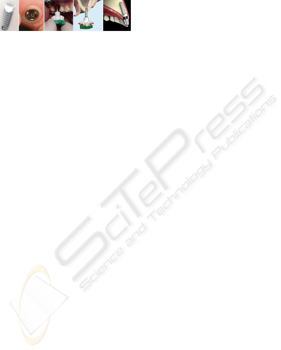
Figure 1: Example of dental implant fixing process.
posed to implants without immediate load are reduc-
tion of treatment time after surgery, stabilization of
height of the bone and improvement of patient’s aes-
thetics. Nevertheless, the greater limitations of this
method are the risk of implants losses due to lack of
retention, the technical difficulty for the manufacture
of the prosthesis and the mechanical failure (Esposito
et al., 2006) of fixations.
With this new technique, the success of dental
prostheses depends to a great extent on its functional
benefits and interface adjustment between prosthesis
and implant. This fact forces the laboratories to make
exact and much more customized designs for each pa-
tient. Also, what is more important, we cannot make
multiple tests with the patient, as it happened with the
previous technique, so it is due to make a design that
works perfectly. Figure 1 shows the process of an im-
plant placement.
1.2 State of the Art of Dental
CAD/CAM Systems
The first use of CAD/CAM systems in dental field
was in early 80s. One of the main application lines
was its intraoperative use to dental restoration using
ceramic pre-manufactured monoblocks (Mrmann,
2004). The use of structural material of high strength
such as structures based on aluminium or zirconium,
which can only be prepared in a CAD/CAM system,
has increased the lifetime of the restoration lead-
ing to a market expansion during last years. The
greatest companies of the dental sector have already
incorporated specific 3D-design software for dental
prostheses which allows to generate virtual models
improving the accuracy and the automated manufac-
ture of the support structures of the dental prostheses.
On these structures the rest of the prosthesis is
made later. Some of these commercial products
are: CEREC 3D (Sirona Dental Systems) (Mrmann,
2004), Everest (http://www.kavo-everest.com)
and Lava (http://cms.3m.com/cms/US/en/2-
21kzikuFW/view.html).
Basically, all these CAD/CAM systems have three
functional components (J.Strub et al., 2006):
• Data capture or scanning, in order to obtain the
buccal data (dental preparation, adjacent teeth and
dental occlusion geometry).
• CAD for a geometric design of the restoration.
These CAD systems have some simple functional-
ities to geometrically modify the restoration to be
designed. In any case, simulation tools for func-
tional analysis are provided.
• CAM to restoration fabrication. CAM systems
use computer-generated information to shape
physical objects, using subtractive methods (part
of the material of an initial block is removed in or-
der to generate the desired shape) or additive ones.
The additive methods are used in rapid prototyp-
ing which are becoming the most used method
in modern CAD/CAM dental systems (Gebhardt,
2000; Noorani, 2006).
Nevertheless, these systems only cover partially
the prothesis design, excluding simulation of func-
tional and biomechanical behavior. Therefore, MIR-
ACLE project will contribute to develop and to put
into dental sector a methodology of ”digital mockup”
or virtual scale model which is being applied suc-
cessfully in other industrial areas. The results of the
project will allow to do a complete assessment of the
final treatment without the need of physical prosthe-
ses.
This paper is only focused on the CAD/CAM sub-
system developed in order to automatize the process
of manufacturing surgical guides using several 3D
models of the patient’s dental anatomy. With this
in mind, in section 2, a brief explanation of MIRA-
CLE is presented and data capture (patient’s anatomy
importation), registration of different 3D models and
dental splint design will be studied in depth. In sec-
tion 3 a clinical validation of the process of splint
design and manufacture, without considering biome-
chanical analysis and virtual articulator information,
will be presented and finally, some conclusions will
be discussed in section 4.
2 METHOD
MIRACLE system is able to obtain a virtual model
of the prosthesis from the 3D model of the crown,
the patient’s anatomical models obtained from the
CT study and the geometric records of the patient’s
functional characteristics. This virtual model allows
to do the functional and biomechanical validation of
prostheses considering their functional benefits based
on their anatomical characteristics. Advanced CAM
techniques are used for the physical manufacture of
prostheses by means of advanced techniques of fast
manufacturing such as HSM (High Speed Milling and
Rapid Tooling). In order to achieve this goal, high ve-
locity and precise milling machines are used, and also
BIODEVICES 2010 - International Conference on Biomedical Electronics and Devices
236

rapid prototyping/manufacturing equipment based on
SLS (Selective laser Sintering and Stereolitography).
2.1 Patient’s Anatomy Model
Importation and Models
Registration
The first step is the capture of the data. The system
imports two 3D models of the patient’s maxillofacial
anatomy: the 3D model obtained from CT scan (CT
model) and a high precision 3D model obtained by
laser-scanning a physical plaster model (laser model).
The information obtained with both models are com-
plementary. On one hand, the CT model provides in-
formation from different anatomical structures (corti-
cal bone, trabecular core, mandibular canal) although
it usually presents metallic artifacts (specially near
the teeth surface) due to the CT scanning process. In
this model, the dentist will plan the surgery. On the
other hand, the scanned model only provides precise
information about the surface of the teeth, without the
presence of these artifacts. Besides the data acqui-
sition using a CT scanner, an image processing step
is required in order to obtain a precise model of the
patient’s anatomy.
The aim of the image processing step can be
divided into two different but related main lines.
Computer-aided dental planning systems must pro-
vide all the available information to the den-
tists/surgeons assuring enough accuracy to take de-
cisions with high reliability. Planning systems usu-
ally represent a 3D view of the jaw, allowing the spe-
cialist to plan the position of the implant. However,
for a precise dental implant planning, an exhaustive
segmentation of the jaw tissues is necessary, focus-
ing on the mandibular channel, which holds the den-
tal nerve, because its injury could cause lip numb-
ness. Consequently, on one hand, the project focuses
on the improvement of image quality reducing metal
artifacts to enhance the 3D reconstruction (Naranjo
et al., 2009) and, on the other hand, the aim is to seg-
ment the tissues present in the human jaw to provide
reliable information to dentists or surgeons. Our seg-
mentation method, presented in (Llor
´
ens et al., 2009),
has achieved good results in terms of detection and
false alarm probability and merit factors of 96.9993
and 99.7696 for cortical bone and inferior alveolar
nerve, respectively.
Once the system has imported the necessary data,
and the surgeon has planned the location of the pros-
thesis in the CT model, the next step is to register the
laser model and the CT model including the implants
planned by the clinic. All this information must be
referred to the same coordinate system in order to de-
sign the surgical splint. Hence the need of the regis-
tration.
The registration process consists of two steps:
1. A pre-registration stage where the specialist se-
lects manually a set of points in one of the mod-
els and its correspondences in the other. After
that, the models are coarsely registered using the
method proposed by Arun (K.Arun et al., 1987),
which uses the Singular Value Decomposition to
obtain the registration matrix. Figure 2-a shows
the result of this step. On the left, the figure shows
the CT model, the locations of the planned im-
plants marked with numbers, and the points se-
lected by the user for the pre-registration.
2. Registration refinement. To improve the preci-
sion of the registration the Iterative Closest Point
(ICP) algorithm (P.Besl and Mckay, 1992) is used.
This algorithm tries to minimize the difference be-
tween two clouds of points. In our case, only
those areas selected by the specialist, which are
present in both models will be taken into account
in the ICP algorithm. Figure 2-b shows the final
result of the registration process. On the left, the
area selected by the user in order to be taken into
account in the ICP algorithm is highlighted in red.
On the right, the superimposition of both models
is shown.
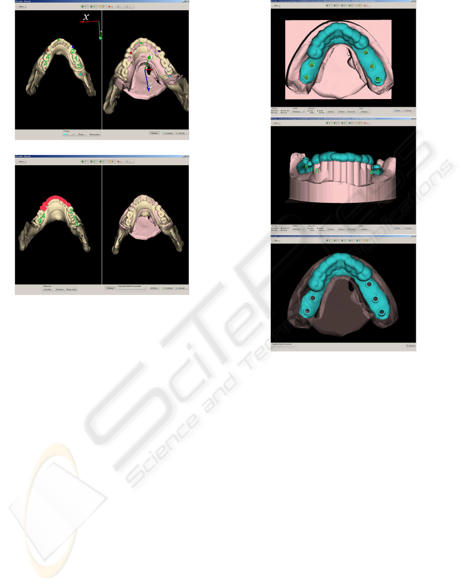
2.2 Surgical Splint Design and
Manufacture
The last step in the process of design using the
CAD/CAM system will be the design of the surgi-
cal splint. The splint is designed using the result of
the registration stage and considering the information
provided by the laser model (surface of the teeth) and
the implant locations, necessary to determine where
the holes in the guide will be needed. Figure 3 shows
different views of the virtual designed splint.
The system performed the simulation of the pros-
thetic abutments, crowns and suprastructures, and the
relationships with the antagonist arch before surgery.
The planning provided information to make surgi-
cal splints by means of stereolitographic techniques.
Stereolithography is a new technology able to provide
physical models solidifying selectively an ultraviolet-
sensitive liquid resin, by means of a laser beam, repro-
ducing the true maxillary and mandibular anatomic
dimensions. With these models, it is possible to make
surgical guides that can place the implants in vivo in
the same places and same directions as those in the
planned computer simulation.
MIRACLE: A CAD/CAM SYSTEM FOR THE MANUFACTURE OF DENTAL SURGICAL SPLINTS
237
a)
b)
Figure 2: Registration results. a)Pre-registration result.
b)ICP algorithm result.
3 VALIDATION AND RESULTS
In this section the validation of the process of splint
design and manufacture, without biomechanics anal-
ysis and articulation data, is presented.
A test set of 23 patients, with mean age of 35
years, has been considered for this study. All the pa-
tients needed rehabilitation treatments from a single
dental piece up to the whole jaw (edentulous patients)
and all they presented common clinical and psycho-
logical parameters. No significant diseases were de-
tected. Particularly, the test set consists of 18 partially
edentulous patients and 5 edentulous ones. The pa-
tient data required for this study consists of medical
history, cast of lower and upper jaw, study of bite reg-
istration in an adjustable articulator and radiographic
diagnosis CT-scan study with Cone Beam technology.
CT data is obtained by means of GE MEDICAL SYS-
TEMS HiSpeed QXi and Philips Medical Systems -
Philips CT Aura.
In order to validate the results obtained by the
planning system CT data was processed and the
placement of the implants was estimated according
some criteria. On one hand, according to anatomi-
Figure 3: Virtual model of the designed splint.
cal criterion, the placement was inferred depending
on the osseous suitability. The implant must be sur-
rounded with the largest available bone extension,
looking for the largest osseointegration surface. On
the other hand, according to prosthetic criterion, start-
ing from the estimated placement as explained above,
the placement was adapted to the antagonist teeth. Di-
ameter and length of the implant were refined.
The implant surgery was done using a standard
protocol. The patient was anesthetized with lido-
caine 2% with 1:100 000 epinephrine. The osteotomy
and subsequent implant-drilling procedures were per-
formed using the personalized surgical-guidance tem-
plate which fitted snugly onto the patient’s teeth dur-
ing the implant procedure. The surgical-guidance
template had 2.2-, 2.8-, and 3.5-sleeve apertures, cor-
responding to each successive drill. Once the final
drill was used, standard implant was placed. Forty
implants were evaluated (in 23 patients). The mean
estimated error was 5.0 degrees. 23 implants (57.5%)
were estimated with errors under 5 degrees. Figure 4
shows the results of the different process steps for a
BIODEVICES 2010 - International Conference on Biomedical Electronics and Devices
238
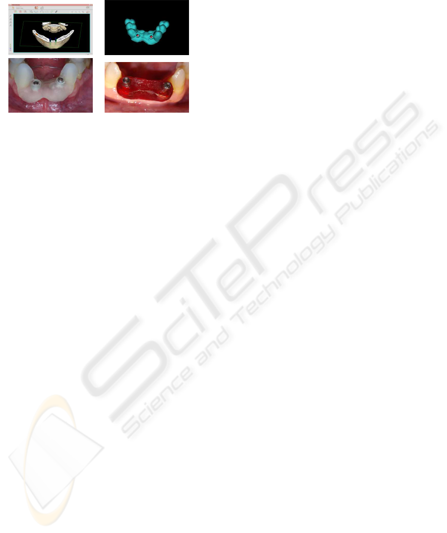
patient: surgical planning, splint design, splint manu-
facture and clinical surgery.
Figure 4: Shaping of splints by means of stereolitogra-
phy. Planning view, virtual surgical splint and real surgical
guide.
4 DISCUSSION
This paper presents MIRACLE project, whose objec-
tive is the development and validation of an intelligent
system for the design, simulation and flexible manu-
facture of implant-supported dental prostheses. The
system, which is still being developed, is described
in this paper. Its efforts are focused on data captur-
ing, surgical planning and surgical guide design and
fabrication.
In order to validate the modules of data capturing,
image processing, planning system and surgical guide
design, an experimental study has been done. Forty
implants were evaluated in 23 patients with mean age
of 35 years. All implants were placed by two step
surgery in the mandible. A surgical template based
on the CT images and on the abutment replica of
the working models was used for the evaluation of
the accuracy of implant placements. The difference
between the proposed and real directions was mea-
sured by the clinical protocol. After surgery the sur-
geons tried to fix the prosthetics crowns designed be-
fore surgery. Errors under 5 degrees were taken as
valid in terms of accuracy. The mean estimated error
was 5.0 degrees. 23 implants (57.5%) were estimated
with errors under 5 degrees. Consequently, this study
proves the accuracy achieved by the system developed
in MIRACLE project.
REFERENCES
Esposito, M., Koukoulopoulou, A., Coulthard, P., and Wor-
thington, H. (2006). Interventions for replacing miss-
ing teeth: dental implants in fresh extraction sock-
ets (immediate, immediate-delayed and delayed im-
plants). Cochrane Database System Review, 4.
Fillies, T., Wiesmann, P., Sommer, D., Joos, U., and
Meyer, U. (2005). Osteoblast reaction on sla and
microgrooved implant surfaces. Mund Kiefer und
Gesichtschirurgie, 9(1):24–28.
Gebhardt, A. (2000). Rapid prototyping. Munich: Hauser.
J.Strub, E.Rekow, and S.Witokowski (2006). Computer-
aided design and fabrication of dental restorations.
JADA, 137(9):1289–1296.
K.Arun, T.Huang, and S.Blostein (1987). Least square fit-
ting of two 3-d point sets. IEEE Transactions on
Pattern Analysis and Machine Intelligence, 9(5):698–
700.
Ledermann, P. (1979). Stegprothetische versorgung
des zahnlosen unterkiefers mit hilfe von plas-
mabeschichteten titan-schaubenimplantaten. Dtsch
Zahnarztl Z, 34:907–911.
Llor
´
ens, R., Naranjo, V., Clemente, M., niz, M. A., and Al-
balat, S. (2009). Validation of fuzzy connectedness
segmentation for jaw tissues. In Bioinspired Appli-
cations in Artificial and Natural Computation, pages
41–47. Springer Berlin / Heidelberg.
Mrmann, W. (2004). The origin of the cerec method: a per-
sonal review of the first 5 years. Int. Journal Comput
Dent, 7(1):11–24.
Naranjo, V., Llor
´
ens, R., Paniagua, P., niz, M. A., and Al-
balat, S. (2009). A new approach in metal artifact re-
duction for ct 3d reconstruction. In Bioinspired Appli-
cations in Artificial and Natural Computation, pages
11–19. Springer Berlin / Heidelberg.
Noorani, R. (2006). Rapid prototyping: Principles and ap-
plications. Hoboken, N.J.: Wiley.
Nuzzolease, E. Immediate loading of two single tooth im-
plants in the maxilla: Preliminary results after one
year. Journal of Contemporary Dental Practice, 6.
P.Besl and Mckay, H. (1992). A method for registration of
3-d shapes. IEEE Transactions on Pattern Analysis
and Machine Intelligence, 14(2).
Schnitman, P., Wohrle, P., and Rubenstein, J. (1990). In-
mediate fixed interim prostheses supported by two-
stage threaded implants: methodology and results.
Journal of Oral Implantology, 19:96–105.
Schroeder, A. (1985). The iti hollow-cylinder implant. in-
ternationales team fur orale implantologie. Schweiz
Monatsschr Zahnmed, 85:876–878.
Uribe, R., Pearrocha, M., and Sanchis, J. (2004). Marginal
peri-implantitis due to occlusal overload: A case re-
port. Medicina Oral, Patologa Oral y Ciruga Bucal,
9.
MIRACLE: A CAD/CAM SYSTEM FOR THE MANUFACTURE OF DENTAL SURGICAL SPLINTS
239
