
DIGITAL COMMUNICATIONS LEARNING TOOLS
gtTAL: Graphical Tool for Testbed-assisted Learning
Jos
´
e A. Garc
´
ıa-Naya, H
´
ector J. P
´
erez-Iglesias, Adriana Dapena and Miguel Gonz
´
alez-L
´
opez
Department of Electronics and Systems, University of A Coru
˜
na, Spain
Keywords:
Digital communications, Multiple-antenna testbed, Testbed-assisted learning.
Abstract:
We introduce gtTAL, a graphical tool implemented on top of a distributed multilayer architecture which is
specifically suitable for multiple-antenna hardware testbeds. gtTAL helps in teaching digital communications
by allowing interaction with the hardware testbed at an abstraction level suitable for undergraduate students.
Instead of using the low-level interfaces provided by hardware manufacturers, the multilayer software archi-
tecture supplies a high level interface access for testbeds, releasing students from the necessity of knowing
low-level details of the hardware to start to practice with it. Therefore, they can easily test algorithms without
developing a new program from scratch, speeding up the time needed for both the implementation and the
debugging tasks. Indeed, the multilayer software architecture allows learning how to deal with real-world dig-
ital communication systems at different abstraction levels, varying from the lowest level software running in
real-time in DSPs or FPGAs, to the highest level software like gtTAL. These three elements: hardware testbed,
multilayer software architecture and graphical tool (gtTAL), constitutes what we termed testbed-assisted learn-
ing.
1 MOTIVATION
In wireless digital communication courses is common
to use computer simulations to illustrate the theoret-
ical concepts presented to the students. Unless very
complex simulations are carried out, the most typ-
ical simulations in graduate courses show the cor-
responding results under controlled and ideal condi-
tions. Thus, very important effects introduced by
hardware elements are often ignored, like for exam-
ple those caused by the antennas, by the D/A and
A/D converters or by the radio-frequency (RF) am-
plifiers. Some of these effects can only be well under-
stood if the students experience the problem by them-
selves. For this reason, computer simulations are only
useful as an starting point in understanding the key
concepts of modern wireless digital communications.
However, computer simulations do not allow to study
and understand very important implementation issues
present in real-world transceivers.
There is a variety of multi-antenna testbeds that
provides many educational opportunities (Rao et al.,
2004), allowing the students to learn, step by step,
all signal processing stages involved in the generation
of the signals to be transmitted through the antennas.
This transmit signal processing chain is very similar
to that usually found in computer simulations. How-
ever, when the students have to implement the corre-
sponding signal processing blocks of a real-world re-
ceiver, they find several important differences. Some
of them are caused by implementation impairments,
i.e. frequency and phase noise or non-linear distor-
tions caused by RF power amplifiers. Other differ-
ences are inherent to the fact that transmitter and re-
ceiver are situated at different physical locations.
Consequently, both time and frequency synchro-
nization steps have to be carried out prior to any other
operation. Also, some operations like filtering, dec-
imation and channel estimation (instead of perfect
channel knowledge) are mandatory. In contrast to
computer simulations, the sources of error are now
out of control, which on one hand makes analyzing
the results more difficult but, on the other hand, the
students have to deal with a more realistic problem.
It is important to stress that some effects can also be
seen, and later understood, if the whole system im-
plementation is considered. For example, most of
the theoretical multiple-antenna models consider the
same average gain for all individual single-antenna
links. However, testbed measurements show that this
is not true and the average gain depends on the spe-
cific propagation seen by each of the transmit-receive
419
A. García-Naya J., J. Pérez-Iglesias H., Dapena A. and González-López M. (2010).
DIGITAL COMMUNICATIONS LEARNING TOOLS gtTAL: Graphical Tool for Testbed-assisted Learning.
In Proceedings of the 2nd International Conference on Computer Supported Education, pages 419-426
DOI: 10.5220/0002784904190426
Copyright
c
SciTePress

Tx PC
• Middleware
• Signal
Processing Layer
Network
Rx PC
• Middleware
• Signal
Processing Layer
Student PC
• End-User Layer
• gtTAL
Figure 1: General organization of the testbed and the stu-
dent PC running gtTAL.
antenna pairs.
In addition, being able to implement and test al-
gorithms in a testbed requires more multi-discipline
skills than the theoretical approach. For instance,
implementing a time synchronization algorithm in a
testbed requires to deal with low-level details of the
testbed hardware components, as for example the type
and format of the A/D converter outputs. Also, it re-
quires skills in instrumentation equipment usage (e.g.
oscilloscopes, spectrum analyzers, network analyz-
ers, etc.). In summary, testbed-assisted learning pro-
vides a much wider perspective of communications
engineering to the student.
The rest of this paper is organized as follows.
2 shows the main contributions provided by the
so-called testbed-assisted learning. 3 presents the
distributed multilayer software architecture of the
testbed, 4 describes the testbed hardware components,
and 5 details the architecture layers. 6 illustrates how
to use gtTAL in a digital communications lesson. Fi-
nally, 7 is devoted to the conclusions.
2 BENEFITS OF
TESTBED-ASSISTED
LEARNING
Some of the most relevant researchers in the field
of digital wireless communications (e.g. (Rao et al.,
2004)) claim that students involved in testbed im-
plementations experience a work that is more time-
consuming, but more rewarding than single-discipline
tasks. For instance, rarely will a communication the-
ory student need to spend time understanding the im-
pact of I/Q imbalances, while a student working on
a testbed has to take into account such effects. Also,
students working on system implementations notice
that the testbed approach is more detailed and com-
prehensive than only theory and computer simula-
tions. Therefore, the testbed approach leads to a
greater satisfaction in seeing a fully functional testbed
transmitting and acquiring real-world signals.
Being involved in testbed development tasks
forces the student to work in a multidisciplinary envi-
ronment (e.g. computer engineers and electrical engi-
neers use to work together in the development of such
testbeds). The student learns how to work in a team
and also how to discuss with senior members about
different issues found during the implementation.
During the last years, different general-purpose
multiple-antenna testbeds have been constructed to
evaluate the performance of diverse signal process-
ing techniques and/or standards (e.g. (Caban et al.,
2006; Borkowski et al., 2006)). At a first glance, one
may think that undergraduate students can participate
in the development of testbeds but, in fact, only post-
graduate students with high expertise are involved in
such teams. Unfortunately, setting up and later de-
velop software allowing to transmit, acquire and prop-
erly process signals involves cumbersome low-level
programming to access the hardware, making diffi-
cult to test new methods which allows the students
to start to interact with testbeds (Rupp et al., 2007).
Due to this reason, it is convenient to add a mecha-
nism to the testbed that allows to access it at differ-
ent levels of abstraction. This means that a student
starting to implement his first algorithms should ac-
cess the testbed at a higher level than another student
who is prepared to deal with more low-level details of
the testbed. Consequently, such a mechanism allows
the students to focus exclusively on the development
and proof techniques, releasing them from the task of
low-level programming.
Our aim is, thus, to provide a mechanism that
allows even undergraduate students to access the
testbed at an abstraction level similar to that of com-
puter simulations. Once the student acquires skills
enough to deal with lower level details, this mecha-
nism should also permit using the testbed but still hid-
ing even lower level details. The understanding of a
multi-layer scheme, where each layer deals with spe-
cific problems at a different abstraction level, clearly
leads to enforce the knowledge of the students.
To the knowledge of the authors, a multitude of
universities as well as public and private research cen-
ters have been investing a lot of efforts in setting up
testbeds with research purposes. However, very few
works (i.e. (Rao et al., 2004)) consider the possibil-
ity of taking advantage of the educational possibilities
offered by testbeds. Therefore, we introduce the term
“testbed-assisted learning” that consists in involving
CSEDU 2010 - 2nd International Conference on Computer Supported Education
420
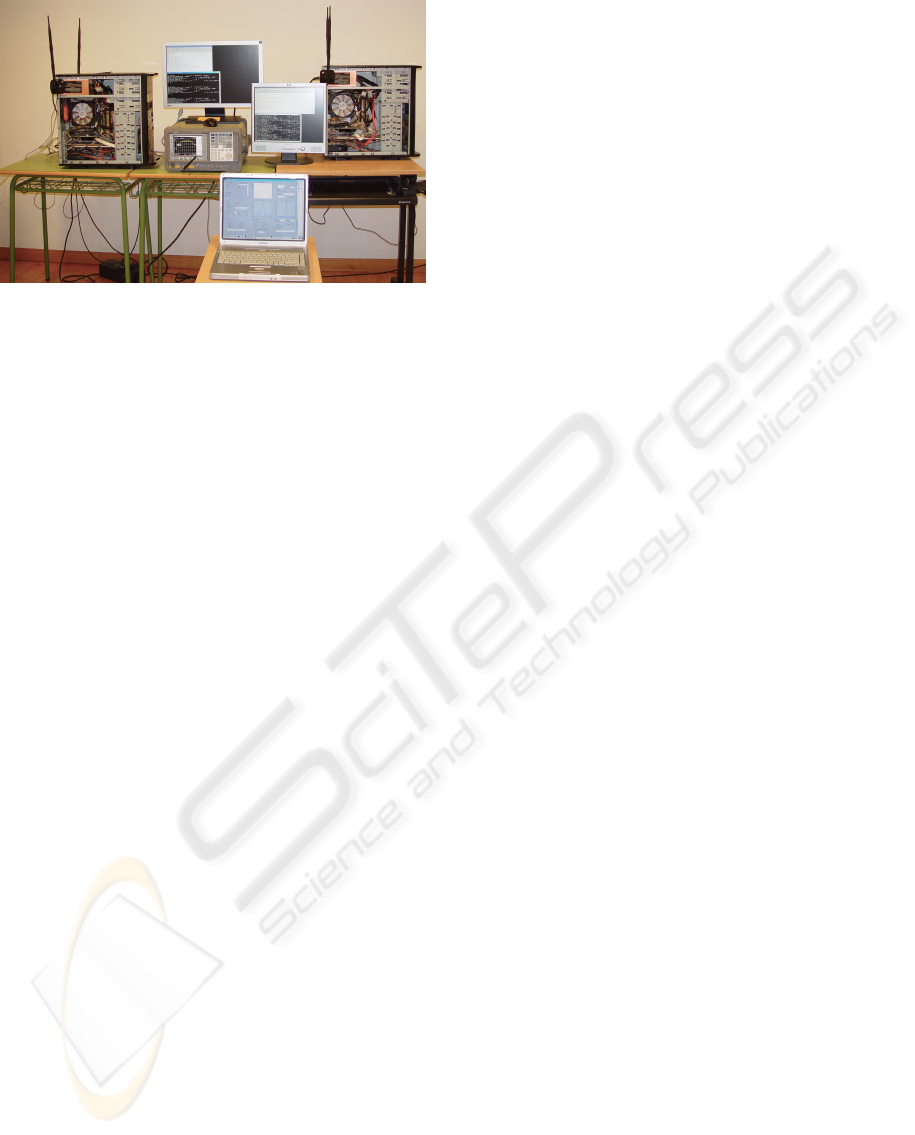
Figure 2: Testbed picture showing the Tx PC, the Rx PC,
and gtTAL running on a laptop.
testbeds in the learning process. This approach is not
restricted to the wireless communications field but our
testbed and most of our research knowledge comes
from this area. Consequently, we will restrict our dis-
cussion to this field.
3 TESTBED OVERVIEW
In Figure 1, the general organization of our testbed
is shown. The testbed is hosted by two ordinary PCs
(see Figure 2), one for the transmitter (referred to as
Tx PC), and another one for the receiver (called Rx
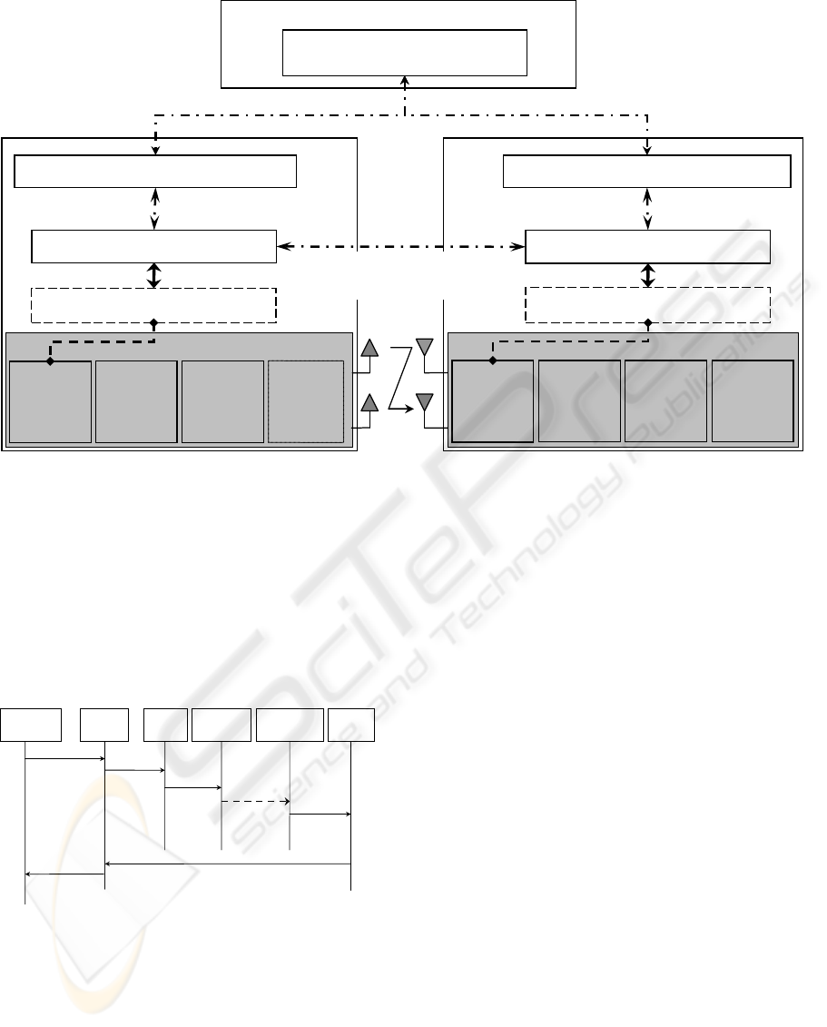
PC). Figure Figure 3 shows the block diagram of the
entire system. Three main parts can be distinguished
(from bottom to top): the testbed hardware that al-
lows us to transmit discrete-time signals over multi-
ple antennas at 2.4 GHz; the multilayer software ar-
chitecture that makes the hardware accessible to end
users (in the following, we consider the students also
as end users of the testbed); and finally, the graphi-
cal tool gtTAL, which is implemented on top of the
multilayer software architecture.
The lowest level layer (i.e. the middleware) is re-
quired to be installed in the same computers as the
testbed hardware is hosted, but the other two layers
can be installed in any other available PCs. However,
the configuration we present here simplifies the set-
up because all software needed is installed in the Tx
PC and in the Rx PC. Only the user layer is installed
together with gtTAL in the student PCs (see Figure 1).
The multilayer software architecture presented
above provides a high abstraction level, which allows
to implement user applications without knowing the
testbed hardware details. For instance, in this paper
we present gtTAL, a graphical tool designed to ex-
plain the so-called Alamouti code (Alamouti, 1998),
constituting one of the simplest and most known
space-time block codes frequently used to introduce
multiple-antenna systems to the students. Such graph-
ical application (detailed below) constitutes the fun-
damental tool to enable the teacher to show the main
effects caused by real-world transmissions through
the testbed. In this work we will restrict our approach
to describe the benefits provided by the use of such
tool in an academic environment, but the testbed plus
the software architecture also enables many teaching
possibilities for more advanced students (e.g. access-
ing the testbed at specific layers).
4 TESTBED HARDWARE
DESCRIPTION
A picture of the Testbed PCs (Tx PC and Rx PC) is
shown in Figure 2. The hardware of the testbed is
entirely based on Sundance Multiprocessor Ltd (see
the bottom of Figure 3). The transmitter is based on a
PCI carrier board SMT310Q and the SMT365, a basic
processing module equipped with an FPGA, a DSP,
memory buffers and two buses capable to sustain a
transfer rate of 400 MB/s. The basic processing mod-
ule is directly connected to the data acquisition mod-
ule (DAQ module), the SMT370. It contains a dual
D/A converter with dedicated memory accessible at
the same speed of the D/A converter. The DAQ mod-
ule also has two A/D converters. Finally, the DAC
module is connected to the RF front-end module, the
SMT349, which performs up and down conversion
operations from 70 MHz to 2.45 GHz with 16 MHz
of maximum bandwidth. The receiver employs the
same configuration as the transmitter (see the bottom
of Figure 3) but incorporating a buffer memory mod-
ule, the SMT351, allowing to store in real-time the
data acquired by the A/D converters to be later trans-
ferred to the Rx PC.
In order to show the advantages derived from the
use of a multilayer software architecture, we will ex-
plain a frame transmission step by step (see Figure 4).
• Once the symbols to be transmitted have been
generated at the graphical tool, a function is called
passing to it the corresponding symbol vectors
(one vector per transmit antenna).
• These symbols are sent to the signal processing
layer (TXPROC) through the user layer, where
they are converted to pass band signals that are
subsequently sent to the middleware.
• When both the Tx PC and the Rx PC are ready to
complete a transmission, the signals are passed to
the testbed hardware to be transmitted through the
antennas.
DIGITAL COMMUNICATIONS LEARNING TOOLS gtTAL: Graphical Tool for Testbed-assisted Learning
421
Sundance SMT310Q
Sundance SMT310Q
SMT370
1 dual DAC
4 MB memory
2 x ADC
FPGA Virtex II
Middleware – TxDSP
PCI Bus
PCI Bus
Tx PC
Rx PC
Middleware – RxHost
Middleware – RxDSP
Middleware – TxHost
Socket connection
Frame synchronization
Signal Processing Layer – TxProc
Signal Processing Layer – RxProc
Student PC
gtTAL
User Layer
Socket connection
Socket connection
Socket connection
Socket connection
SMT365
DSP@600 MHz
FPGA Virtex-II
16 MB memory
SHB buses
SMT365
DSP@600 MHz
FPGA Virtex-II
16 MB memory
SHB buses
SMT351
1 GB FIFO
memory for the
SHB buses
SMT349
IF ↔ RF
16 MHz BW
IF 70 MHz
RF 2.45 GHz
SMT370
1 dual DAC
4 MB memory
2 x ADC
FPGA Virtex II
SMT349
IF ↔ RF
16 MHz BW
IF 70 MHz
RF 2.45 GHz
Figure 3: Platform Scheme.
• At the receiver side, the middleware stores the sig-
nals into the hardware buffers and then they are
forwarded to the receiver signal processing layer
(RXPROC).
• Finally, the acquired signals are forwarded to the
user application through the user layer, complet-
ing the entire process.
function call
symbol/sample
sequences
gtTAL
User
Layer
TxProc
Middleware
Tx
Middleware
Rx
RxProc
socket
connection
discrete
symbol
sequences
socket
connection
IF signals
RF
transmission
socket
connection
acquired IF
signals
socket
connection
acquired
symbol/sample
sequences
function
return
acquired
symbol/sample
sequences
Figure 4: Example of a transmission using gtTAL, the dis-
tributed multilayer software architecture, and the testbed
hardware.
The user layer allows configuring several param-
eters. For example, the signal processing layer can
perform time and frequency synchronization or ac-
quire non-synchronized signals, also raw data or al-
ready demodulated discrete symbols can be acquired.
5 ARCHITECTURE LAYERS
This section describes the three layers developed by
us to provide high-level access to the testbed (see Fig-
ure 3): the user layer, the signal processing layer and
the middleware layer.
5.1 User Layer
The user layer interacts with the user application (the
graphical tool in this case) by using a simple func-
tion implemented in MATLAB
®
(any other software
implementing socket connections is also valid). Its
main task consists in sending to the signal processing
layer the symbols to be transmitted plus the necessary
parameters, at the transmitter side. In the same way,
the user layer receives the acquired symbols, being
noticed if any error occurs.
The main target of the user layer is making the rest
of the layers accessible to the high level applications,
taking into account the type of development environ-
ment they use. For this reason, the user layer is jointly
executed with that application (see Figure 3).
5.2 Signal Processing Layer
The signal processing layer is network-connected
with both the user and the middleware layers (see Fig-
CSEDU 2010 - 2nd International Conference on Computer Supported Education
422

ure 3). It provides remote access and makes them in-
dependent with respect to the other layers. This layer
consists of two different processes that carry out the
signal processing operations needed to link the user
and middleware layers. The first process (TXPROC)
receives the symbol vectors from the user layer and
performs the up sampling, pulse-shape filtering, I/Q
modulation and frame assembling operations in or-
der to generate the IF signals that will be sent to the
middleware. Similarly, the second process (RXPROC)
waits for the acquired signals from the middleware
and performs the time and frequency synchronization
operations followed by the I/Q demodulation, filtering
and down sampling. The resulting vectors are sent to
the user layer.
5.3 MIDDLEWARE LAYER
The middleware concept constitutes a great leap for-
ward in multiple-antenna testbed technology, making
the testbed hardware accessible through ordinary net-
work connections. This layer fills the gap between the
testbed hardware and the signal processing layer, al-
lowing discrete-time signals to be transferred through
the PCI bus and making possible the synchronization
between the Tx PC and the Rx PC using a network
connection.
The middleware architecture is split into two dif-
ferent sub-layers (see Figure 3). The top sub-layer is
responsible of establishing the network connections
between the transmitter and the receiver, and with the
higher layer (the signal processing layer). The bottom
sub-layer corresponds to the testbed hardware config-
uration and control software.
The middleware is constituted by four different
processes. The first two (TxHost and RxHost) im-
plement the so-called top sub-layer and run, respec-
tively, on the Tx PC and the Rx PC. They are im-
plemented in standard C++ language and use sockets
to establish the necessary network connections: one
between TxHost and RxHost processes (used to syn-
chronize the transmitter and the receiver, thus the re-
ceiver knows when the signal acquisition process has
to start); another one, established between the TX-
HOST process and the Tx signal processing layer;
and, finally, another one between the RXHOST pro-
cess and the Rx signal processing layer. The re-
maining two processes are the transmitter and the
receiver processes that run on their respective Digi-
tal Signal Processors (DSPs) available in the testbed
hardware. They implement the so-called bottom sub-
layer. The transmitter DSP process (TXDSP) per-
forms data transfers through the PCI bus jointly with
the TXHOST process and configures and controls
the hardware components at the Tx PC. In the same
way, the RXHOST process and the DSP receiver pro-
cess (RxDSP) are responsible of transferring the data
through the PCI bus and, from the DSP side, con-
trolling and configuring the testbed hardware compo-
nents at the Rx PC.
6 A LESSON IN DIGITAL
COMMUNICATIONS
Thanks to the abstraction level of our distributed ar-
chitecture, it is very easy to devise a graphical tool for
testbed-assisted learning (gtTAL). This tool helps in
explaining basic concepts about wireless digital com-
munication transceivers, including multiple-antenna
systems. For instance, we have developed a first re-
lease of gtTAL oriented to explain Orthogonal Space-
Time Codes (OSTBC), including the popular 2×1
Alamouti OSTBC (Alamouti, 1998).
The students should be familiar with some ba-
sic concepts in the field of wireless digital commu-
nications, such as modulation types (e.g. PAM, PSK,
QAM), symbol rate and bandwidth, the concept of
SNR (Signal-to-Noise Ratio), matched filtering, etc.
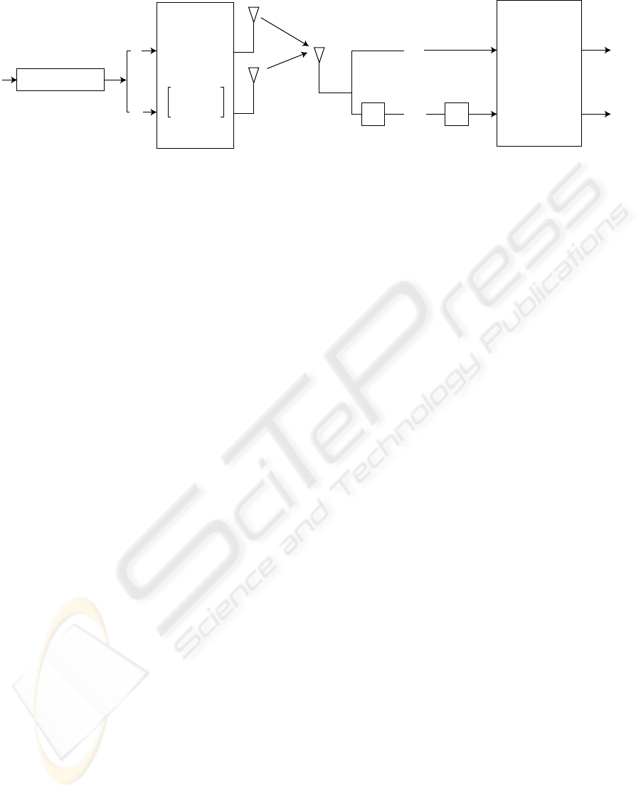
6.1 The 2×1 Alamouti OSTBC
Signal Model
Let us start with the explanation describing the base
band model of the 2×1 Alamouti OSTBC. Two anten-
nas are used at the transmitter side and only one an-
tenna is employed at the receiver side (see Figure 5).
As shown in Figure 5, the input binary data stream b
i
is first mapped to the corresponding symbols, which
are then split into two sub-streams s
1
and s
2
. Each
pair of modulated symbols {s
1
, s
2
} is then transmit-
ted during two consecutive time slots using the fol-
lowing strategy: during the first time slot, s
1
and s
2
are respectively transmitted through the first and the
second antenna. During the second time slot, −s
∗
2
is
transmitted through the first antenna while s
∗
1
is trans-
mitted through the second one
1
.
Since the source symbols are sent through the an-
tennas during two consecutive time slots, they experi-
ence different fading realizations h
1
and h
2
(see Fig-
ure 5), but the fading value is assumed to be the same
during two time slots (i.e. a block fading channel with
a duration of at least two channel uses). Hence, the
1
The operator (·)
∗
denotes complex conjugation.
DIGITAL COMMUNICATIONS LEARNING TOOLS gtTAL: Graphical Tool for Testbed-assisted Learning
423
Alamouti
STBC
Compute
ˆ
H
ˆ
s
=
ˆ
H
H
x
z
− 1
s
1
h
1
h
2
z
2
( )
*
z
1
ˆs
2
ˆs
1
s
2
x
2
= z
*
2
x
1
= z
1
s
1
s
2
s
*
1
−s
*
2
b
i
Modulator
Figure 5: Alamouti OSTBC scheme.
signal received during the first time slot has the fol-
lowing form:
z
1
= s
1
h
1
+ s
2
h
2
+ n
1
. (1)
Given that the channel remains constant during two
time slots, the observation in the second time slot is
given by
z
2
= s
∗
1
h
2
− s
∗
2
h
1
+ n
2
. (2)
In the expressions presented above, n
i
denotes the ad-
ditive white Gaussian noise (AWGN). By defining the
vector of observations as:
x = [x
1
, x
2
]
T
= [z
1
, z
∗
2
]
T
(3)
where the operator (·)
T
stands for the transposition.
The relationship between the observation vector x and
the source vector s = [s
1
, s
2
]
T
is given by
x = Hs + n (4)
where n = [n
1
, n
∗
2
]
T
is the noise vector and H repre-
sents the (2 × 2) matrix obtained following the Alam-
outi coding scheme from the two channel coefficients
h
1
, and h
2
(mixing matrix):
H =
h
1
| h
2
=
h
1
h
2
h
∗
2
−h
∗
1
(5)
It is interesting to note that H is unitary up to a scalar
factor:
HH
H
= H
H
H = khk
2
I
2
(6)
where khk
2
= |h
1
|
2
+ |h
2
|
2
is the squared Euclidean
norm of the channel vector, I
2
is the 2×2 identity ma-
trix and (·)
H
denotes the Hermitian operator. Conse-
quently, the transmitted symbols can be recovered up
to scalar factor:
ˆ
s =
ˆ
H
H
x
where
ˆ
H is a suitable estimate of the mixing matrix.
As a result, this scheme supports maximum likelihood
(ML) detection based only on linear processing at the
receiver.
Channel Estimation Strategies
The performance of communication systems based
on the Alamouti coding scheme strongly depends on
the accurate estimation of the channel matrix H. For
this reason, this lesson is focused on supervised and
unsupervised algorithms to estimate the mixing ma-
trix. The standard way to estimate this matrix con-
sists in utilizing pilot symbols (Budianu and Tong,
2001) known by both the transmitter and the receiver.
Among the supervised methods, the Least Squares
(LS) criterion (Haykin, 2001) constitutes a frequent
starting point, given the simplicity of the resulting
technique.
The main inconvenient caused by the use of pilot
symbols is the energy spent during their transmission.
Because pilot symbols do not convey data, the result
is a loss in terms of spectral efficiency. This drawback
can be avoided by using unsupervised approaches
(also known as blind channel estimation methods).
Blind Source Separation (BSS) algorithms can esti-
mate the mixing matrix, H, and therefore the realiza-
tions of the source vector s, from the corresponding
observations x. The lack of a priori knowledge may
limit the achievable performance, but makes blind ap-
proaches more robust to calibration errors (i.e. devia-
tions from the assumed theoretical model) than con-
ventional array processing techniques (Cardoso and
Souloumiac, 1993). The best known BSS algorithms
are the so-called joint approximate diagonalization of
eigenmatrices (JADE), and FastICA (Bingham and
Hyv
¨
arinen, 2000). More recently, specific algorithms
for OSTBCs have been designed taking advantage of
the specific structure of these codes (e.g. (Beres and
Adve, 2007)).
6.2 Exercise
Our graphical software tool, gtTAL, allows testing ei-
ther with complex-valued discrete symbol sequences
CSEDU 2010 - 2nd International Conference on Computer Supported Education
424
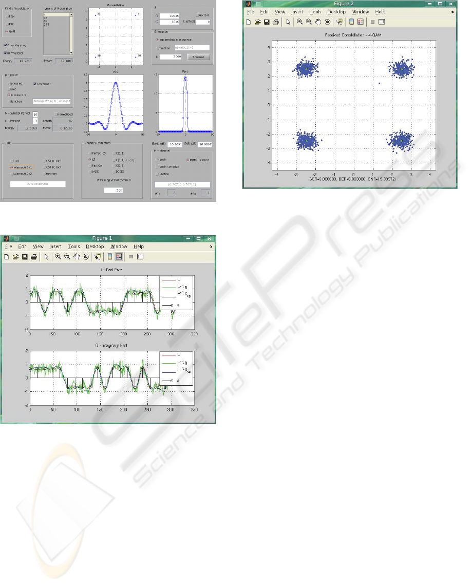
Figure 6: Screen shot of gtTAL main window.
Figure 7: Result window showing the transmitted symbols
(black) and signals (red), the acquired signals after the I/Q
demodulation (green), and after the matched filter (blue).
or pulse-shaped signals, both base band or pass band.
In all cases, the signals are transmitted using the
testbed or through randomly generated channels (i.e.
like in a conventional computer simulation). Sev-
eral parameters can be modified such as the num-
ber of bits to be transmitted, or how they are gen-
erated (equiprobable source or using a function pro-
vided by the user); the modulation type (PAM, PSK
or QAM), and the number of levels of the modula-
tion; the number of samples for each symbol or the
pulse-shape form to be used (square, root raise cosine
or user-defined). Figure 6 shows the main window of
gtTAL, used to introduce these parameters. Students
can measure the performance of several channel es-
Figure 8: Symbol constellation corresponding to the ac-
quired signals.
timation algorithms (Least Squares, Fast-ICA, JADE,
etc.) and compare it with the performance obtained
when perfect channel state information is available at
the receiver side. In the latter case, it is required that
the mixing matrix H be randomly generated using dif-
ferent distribution models (i.e. not using the testbed).
For example, the parameters introduced in the
main window of gtTAL shown in Figure 6 allows
to generate k = 2000 equiprobable bits mapped us-
ing the Gray code. The symbols are 4-QAM modu-
lated, filtered using a root raised cosine pulse shape,
and finally, the symbols are space-time coded using
the Alamouti scheme. gtTAL displays the modulation
constellation and the pulse shape.
After pressing the “Transmit” button, the se-
quence is transmitted over the testbed as it is shown
in Figure 4, and the tool plots Figure 7 and Figure 8.
Figure 7 shows the transmitted signal s
1
(another fig-
ure is plotted for s
2
), the transmitted symbol values,
the transmitted signal after the pulse-shape filter, and
the acquired signals after the matched filter. Figure 8
shows the received symbol constellation. At the bot-
tom of the figure, the estimated values for the symbol
error ratio (SER), the bit error ratio (BER) and the
signal-to-noise ratio (SNR) are displayed.
7 CONCLUSIONS
We have introduced gtTAL, a graphical tool to help
in the teaching process of wireless digital communi-
cations. In its current release, gtTAL results very ad-
equate to explain the basic concepts about space-time
block codes for multiple-antenna transceivers. In par-
DIGITAL COMMUNICATIONS LEARNING TOOLS gtTAL: Graphical Tool for Testbed-assisted Learning
425

ticular, it includes the well known Alamouti space-
time code. Also, it offers the possibility of using dif-
ferent channel estimation strategies, including super-
vised and unsupervised methods.
gtTAL can be used as a conventional graphical
user interface to perform computer simulations, i.e.
without needing any additional hardware component.
However, its main potential resides on its ability to
transmit and acquire signals by using a hardware
testbed. To do so, gtTAL perfectly integrates with a
distributed multilayer software architecture, that en-
ables to access the hardware testbed avoiding low-
level programming. In this sense, gtTAL represents a
high-level tool to operate a hardware testbed. Thus,
even undergraduate students can easily experiment
with real data transmissions in realistic environments.
This clearly contributes to increase their motivation as
well as their personal reward in learning digital com-
munications.
The hardware testbed, the multilayer software ar-
chitecture, and gtTAL, constitute what we termed
testbed-assisted learning.
ACKNOWLEDGEMENTS
This work has been funded by the Xunta de Gali-
cia, the Ministerio de Ciencia e Innovaci
´
on of Spain,
and the FEDER funds of the European Union under
the grants with numbers 09TIC008105PR, TEC2007-
68020-C04-01, and CSD2008-00010.
REFERENCES
Alamouti, S. (1998). A simple transmit diversity technique
for wireless communications. IEEE Journal on Se-
lected Areas in Communications, 16(8):1451–1458.
Beres, E. and Adve, R. (2007). Blind channel estimation for
orthogonal stbc in miso systems. IEEE Transactions
on Vehicular Technology, 56(4):2042–2050.
Bingham, E. and Hyv
¨
arinen, A. (2000). A fast fixed-
point algorithm for independent component analysis
of complex valued signals. International Journal of
Neural Systems, 10:1–8.
Borkowski, D., Br
¨
uhl, L., Degen, C., Keusgen, W.,
Alirezaei, G., Geschewski, F., Oikonomopoulos, C.,
and Rembold, B. (2006). SABA: A testbed for real-
time MIMO system. EURASIP Journal on Applied
Signal Processing, 2006.
Budianu, C. and Tong, L. (2001). Channel estimation for
space-time orthogonal block codes. In IEEE Inter-
national Conference on Communications, ICC 2001,
volume 4, pages 1127–1131.
Caban, S., Mehlf
¨
uhrer, C., Langwieser, R., Scholtz, A. L.,
and Rupp, M. (2006). Vienna MIMO Testbed.
EURASIP Journal on Applied Signal Processing,
2006, Article ID 54868.
Cardoso, J. and Souloumiac, A. (1993). Blind beamforming
for non-gaussian signals. IEE Proceedings F Radar
and Signal Processing, 140(6):362–370.
Haykin, S. (2001). Adaptive Filter Theory. Prentice Hall
Information and System Sciences Series, 4th edition.
Rao, R., Zhu, W., Lang, S., Oberli, C., Browne, D., Bhatia,
J., Frigon, J.-F., Wang, J., Gupta, P., Lee, H., Liu, D.,
Wong, S., Fitz, M., Daneshrad, B., and Takeshita, O.
(2004). Multi-antenna testbeds for research and edu-
cation in wireless communications. IEEE Communi-
cations Magazine, 42(12):72–81.
Rupp, M., Caban, S., and Mehlf
¨
uhrer, C. (2007). Chal-
lenges in building MIMO testbeds. In Proc. of the 13th
European Signal Processing Conference (EUSIPCO
2007), Poznan, Poland.
CSEDU 2010 - 2nd International Conference on Computer Supported Education
426
