
PATTERN RECOGNITION FOR FAULT DIAGNOSIS OF
SOLAR POWER INVERTER BY TRAJECTORY IMAGE
UNDERSTANDING
Jaeho Hwang
1
, Nanhwa Kim
1
, Neajoung Kwak
1
and Wonpyo Hong
2
1
Dept. of Electronic Eng., Hanbat National University, Daejeon 305-719, Korea
2
Dept. of Building Services Eng., Hanbat National University, Daejeon 305-719, Korea
Keywords: Pattern Recognition, Image Understanding, Fault Diagnosis, Decision Tree.
Abstract: This paper presents an approach based on pattern recognition to detect and diagnose faults of solar power
inverter by its fault trajectory image understanding. The drive system for simulation is modeled using
Matlab Simulink toolboxes. Solar power device uses control/filter structure to connect the pulse width
modulation (PWM) inverter. Multistage diagnosis factors are calculated from faults patterning procedure. It
is based on the analysis of the vector trajectory and of the space syntax in faulty image mode.
1 INTRODUCTION
A Solar power inverter is a type of power electronics
inverter that is made to convert the DC electricity
from photovoltaic solar cells into AC sinusoidal one
under various kinds of load, building appliances and
a utility grid. In case of medium voltage solar
inverter, switching mode PWM converters have
been widely used because of its high efficiency and
output power. However, electrical faults may exist in
any component of the drive system. Once abrupt
faults such as the breakdown of switching devices,
the failure of the capacitor or inductor in the low-
pass filter occur, the whole system will lose its
operation and even propagate a series of troubles to
whole power system. In addition to electronic
troubles, the solar plant output voltage varies in a
wide range. It has to be converged within a specified
range in use of controller and a big input capacitor
which is connected in parallel to the solar cells in
order to fit the input voltage of DC-to-AC power
inverter. The troubles in this device and input
voltage ripple are the additional faults of solar power
inverter.
The recent researches on fault diagnosis of
power inverters have been focused related to three-
phase induction motor derive system, inverter faults
in variable speed AC drives, load short/open circuit
and mechanical/insulation failure of the induction
motor(Guan et al., 2007, Son et al., 2004, Ye and
Wu, 2001). The method for fault detection and
diagnosis is mainly based on the current trajectory
and its instantaneous frequency at the output side of
the inverter. However, with the increasing concern
about natural energy source and environmental
demand, the need to produce the green energy such
as solar energy to replace fossil fuels has
significantly increased. In an effort to utilize the
solar energy, photovoltaic(PV) generation with
power inverter is an effective method to supply the
flexible power in a grid, not only AC motors,
connected small and large power generation plants.
This paper develops a real-time faulty diagnosis
method for photovoltaic inverter system based on
the pattern recognition of current vector calculation.
The performance and characteristic of the system
faults are evaluated as the type of source image
parameters for patternization.
2 SYSTEM AND FAULT
ANALYSIS
2.1 System Schemes
The scheme of the proposed PV inverter system can
be built in different ways, depending on the size of
the system and on the desired energy management. It
is composed of photovoltaic module, electrical,
electronic device for control, DC/DC converter,
477
Hwang J., Kim N., Kwak N. and Hong W. (2010).
PATTERN RECOGNITION FOR FAULT DIAGNOSIS OF SOLAR POWER INVERTER BY TRAJECTORY IMAGE UNDERSTANDING.
In Proceedings of the International Conference on Computer Vision Theory and Applications, pages 477-480
Copyright
c
SciTePress
inverter and grid. The output power produced by
photovoltaic modules is significantly affected by the
weather conditions. The PV sources depend on solar
radiation and cell temperature during sun hour
period. In order to extract maximum output power
from PV source, solar power controller has to be
incorporated to regulate the voltage to the Maximum
Power Point Tracking(MPPT)(Bellini et al., 2008).
This is achieved through controller of PV inverter
system. Due to vary solar output, night or
intermittent sun condition, battery is used to work as
a standalone power source charged from PV source.
It can be also connected to Grid sources as a backup
source.
The single-stage for PV inverter system,
illustrated in Fig.1, is employed to supply AC power
to an available load. The output voltage is quite low
and the MPPT is controlled by the inverter.
Figure 1: Single-stage PV inverter system.
On the utility inverter, a high frequency Pulse
width modulated(PWM) inverter is designed and
applied in order to maintain a power factor and low
harmonic current, where the stored DC power in the
battery is digitized to produce a sequence of PWM
pulses at the output of inverter.
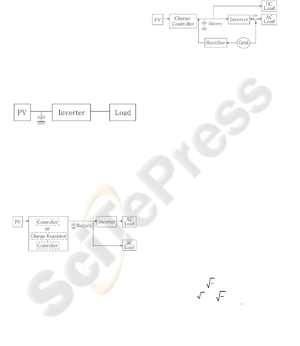
The general scheme for simple PV inverter is
shown in Fig.2. Here the controller or controller
with charge regulator is incorporated to regulate the
output power of PV source.
Figure 2: Grid tie PV inverter system.
The PV output voltage, which can vary in a wide
range, has to be isolated in order to fit the input
voltage of inverter. In case of Fig.2, it is realized by
controller or charge-regulator with controller.
The schematic block diagram, where the grid
system and PV system works as primary and back-
up source, in shown Fig.3.
The system switch connects the inverter during
sun hour and PV supplies electric power to the load
through inverter. During night or intermittent sun
condition, the grid source alone charges the battery
and the load gets its power from the grid. The
system switches over to the grid during inverter cut
off.
Figure 3: Grid tie PV inverter system.
2.2 Fault Analysis
Various types of faults might occur on the different
parts of the PV inverter system, which include the
following:
ⅰ) PV source;
ⅱ) Controller, charge regulator or rectifier:
breakdown of device, faults in the circuit ;
ⅲ) Battery: capacitor breakdown;
ⅳ) Load: one phase-missing, close to ground, short,
open;
ⅴ ) PWM inverter: faults on turning on-off or
thyristor devices;
ⅵ) Grid: switching fault, short;
In this paper, only faults occurred in the invert,
controller, load and grid are considered. The other
faults will be studied in another paper. Switching
faults of PWM inverter, open or short circuit faults
of control devices and defects on load and grid are
analyzed in diagnosis model.
The grid system and PWM inverter are three-
phase devices. The signals used for diagnosis model
are inverter output three-phase currents. The faults
in the inverter drive system due to electrical or
switching causes are reflected in the current wave
form at the output side of the inverter. The three-
phase signals are transformed into a two-phase
rector space by Concordia transform. It transforms a
three-phase system into a further simplified two line
currents based on
0
abc
i i i
.
3
2
a
ii
(1)
1
2
2
ab
i i i
(2)
The trajectory of vector
( , )i i i
is
periodically preserved image on
plane because
the trajectory for each fault mode is unique.
VISAPP 2010 - International Conference on Computer Vision Theory and Applications
478

3 DIAGNOSIS MODEL AND
PATTERN RECOGNITION
The diagnostics of PV inverter which is designed to
draw photovoltaic energy from a battery can be
implemented by checking the trajectory image of the
current vector in
plane(Peuget et al, 1998). It
has its own trajectory mode, normal or faulty one.
They can be plotted for the current of the inverter
and different patterns are easily classified when
switching device faults occur in the inverter. Each
trajectory image represents full or half circle under
ideal operation condition. In case of one switching
fault, the phase currents of the load are no longer
sinusoidal. The current of that phase can flow in one
direction. The phase voltage during the half period
does not appear because the phase current does not
flow in positive or negative state. The phase current
of fault device is null during half of the current
period. The relation between
i
and
i
is
3ii
by equation (1) and (2). Therefore the
corresponding trajectory is a half circle in
plane.
3.1 Diagnosis Parameters
But both switching devices are faulty, the trajectory
becomes a narrow line or a sector within a right
angle. If both devices belong to one phase, the
trajectory moves the
axis for phase A and
becomes one line with 120 degree delay for phase B
and C. If both devices belong to different phase, the
trajectory becomes a sector within a right angle. The
trajectory refers to a fault mode. In order to easily
identify a fault mode of the PV inverter, four
parameters related to the trajectory image are to be
proposed within a normalized unit circle; shape,
region, distributed angle and typical vector angle.
Shape: line, fanwise sector
Region: six regions (Fig. 4)
Figure 4: Trajectory regions.
Distributed angle
,
(Fig. 5(a)):
60 ( ),mm
1, 2,
3
Typical vector angle
,
(Fig. 5(b)):
30 ( ),nn
1,
2,… ,11
Typical vector is decided to halve the distributed
angle.
(a)
(b)
Figure 5: Distributed/typical vector angle (examples).
3.2 Tree for Pattern Classification
In fault analysis, a tree diagram is used as a pattern
recognition model which maps observation about
faults to pattern. The goal is to create a model that
classifies the faults based on the proposed diagnosis
parameters. Each interior node corresponds to one of
the parameters, that is, input variables. This tree can
be learned to refer to the outcome of the fault pattern
(Table1, Fig. 6).
Table 1: Tree configuration.
node 1
node 2
()
pattern
line
b1
b11,90
D1
b12, 150
D2
b13, 210
D3
sector
b2
node 3,
()
node 4,
()
b21, 60
30
n
b211~ b216,
2nk
D4~D9
b22, 120
b221~ b226,
21nk
D10~D1
5
b23, 180
b231~ b236,
2nk
D16~D2
1
0,1,2, ,5, :n b branch
PATTERN RECOGNITION FOR FAULT DIAGNOSIS OFSOLAR POWER INVERTER BY TRAJECTORY IMAGE
UNDERSTANDING
479
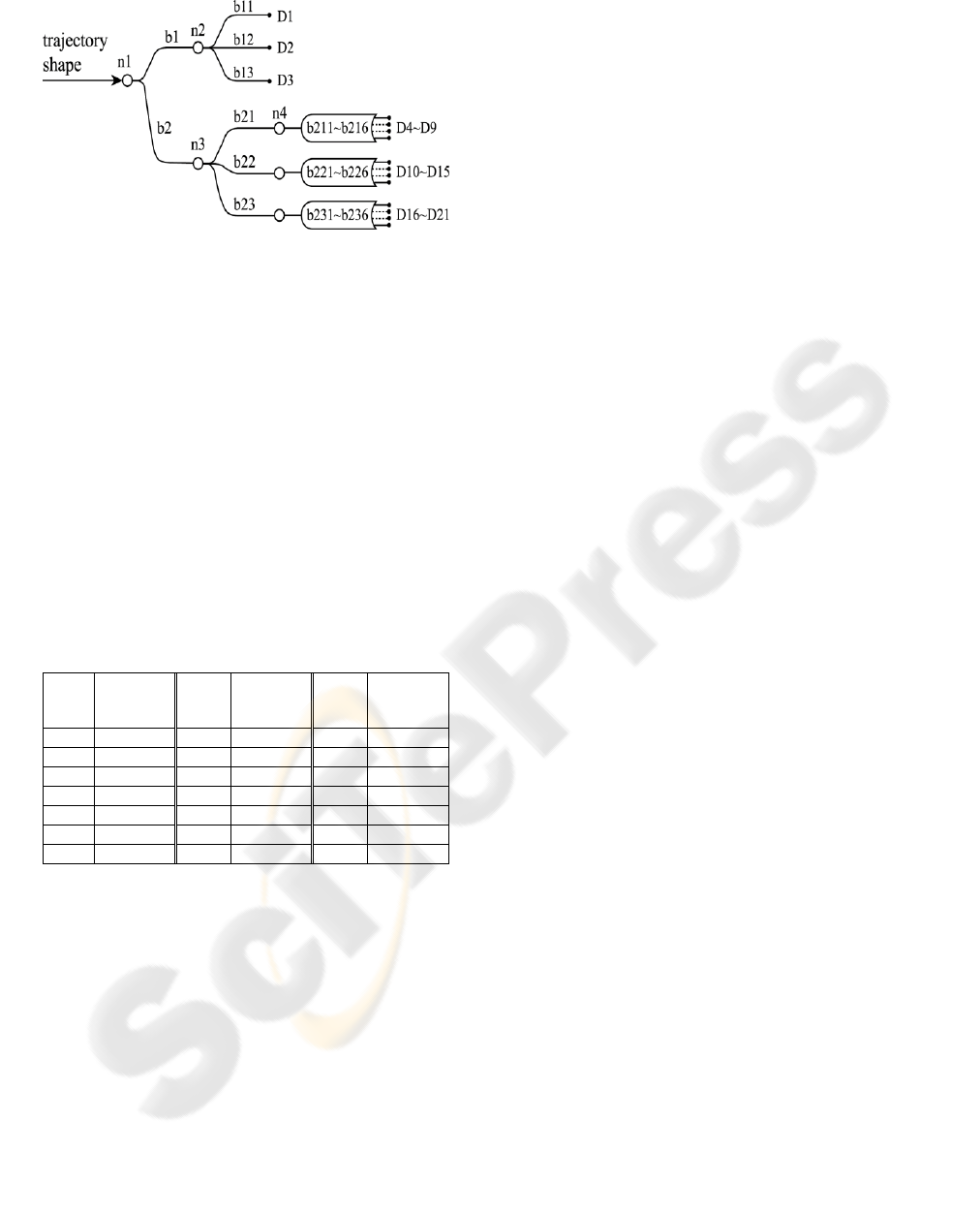
Figure 6: Tree and pattern recognition.
3.3 Simulation for Faulty Pattern
In general the PV inverter is a combination of
electric and electronic devices. The proposed
simulation model for PV inverter is grouped into
several modules provided in Matlab Simulink as
shown in Fig.2. The load current is simulated using
three phase inverter module in SimPowerSystem
library. In table2, the patterns for different faults
modes are listed. The fault refers to the open-
circuited of the relevant power-electronic device.
The devices E1 and E6 are respectively upper and
lower device of phase A. E3 and E2 are related to
phase B, and E5 and E4 refer to upper/lower device
of phase C.
Table 2: Fault patterns.
pattern
open-
circuited
devices
pattern
open-
circuited
devices
pattern
open-
circuited
devices
D1
E1
E6
D8
E1
E5
D15
E5
E6
D2
E4
E5
D9
E2
E6
D16
E6
D3
E2
E3
D10
E3
E6
D17
E3
D4
E3
E5
D11
E3
E4
D18
E4
D5
E4
E6
D12
E1
E4
D19
E1
D6
E1
E3
D13
E1
E2
D20
E2
D7
E2
E4
D14
E2
E5
D21
E5
: and
4 CONCLUSIONS
This paper proposed a method for patternization and
its graphic recognition based on the analysis of
trajectory modes image understanding when three
phase PV inverter faults occur. System schemes and
diverse fault mode are introduced. After parameters
for diagnosis are identified, a decision tree is
composed. The fault pattern can easily diagnose the
each switching fault. This knowledge-based method
has been tested in simulation using Matlab Simulink
toolboxes. The proposed method can apply to an
experimental system.
REFERENCES
Guan, Y., Sun, D., He, Y.(2007).Mean Current Vector
Based Online Real-Time Fault Diagnosis for Voltage
Source Inverter fed Induction Motor Drives, IEEE
International Electric Machines & Drives
Conference,2,1114 – 1118.
Son, H.I., Kim, T.J., Kang, D.W., Hyun, D.S.(2004). Fault
Diagnosis And Neutral Point Voltage Control When
The 3-Level Inverter Fault Occur, IEEE Power
Electronics Specialists Conference
Ye, Z. and Wu, B.(2001). Simulation of Electrical Fault of
Three Phase Induction Motor Drive System, IEEE
Power Electronics Specialists Conference ,1,75 – 80.
Bellini, A., Bifaretti, S., Iacovone, V.(2008). Resonant
DC-DC Converters for Photovoltaic Energy
Generation Systems, SPEEDAM 2008 International
Symposium on Power Electronics, Electrical Drives,
Automation and Motion, 815-820.
Peuget, R., Courtine, S., Rognon, J.(1998). Fault Detection
and Isolation on a PWM Inverter by Knowledge-
Based Model, IEEE Transactions on Industry
Applications, 34(6), 1318-1326.
VISAPP 2010 - International Conference on Computer Vision Theory and Applications
480
