3D RECONSTRUCTION FROM LINE DRAWINGS
Lars H. Wendt
1
, Andr
´
e Stork
2
, Arjan Kuijper
2
and Dieter W. Fellner
1
1
Interactive Graphics Systems Group, TU Darmstadt, Germany
2
Fraunhofer Institute for Computer Graphics Research IGD, Darmstadt, Germany
Keywords:
Sketched-based modeling, Computer-aided design, 3D reconstruction.
Abstract:
In this work we introduce an approach for reconstructing digital 3D models from multiple perspective line
drawings. One major goal is to keep the required user interaction simple and at a minimum, while making no
constraints to the objects shape. Such a system provides a useful extension for digitalization of paper-based
styling concepts, which today is still a time consuming process.
In the presented method the line drawings are first decomposed in curves assembling a network of curves. In
a second step, the positions for the endpoints of the curves are determined in 3D, using multiple sketches and
a virtual camera model given by the user. Then the shapes of the 3D curves between the reconstructed 3D
endpoints are inferred. This leads to a network of 3D curves, which can be used for first visual evaluations
in 3D. During the whole process only little user interaction is needed, which only takes place in the pre- and
post-processing phases. The approach has been applied on multiple sketches and it is shown that the approach
creates plausible results within reasonable timing.
1 INTRODUCTION
Nowadays, digital 3D models are an important ele-
ment in design and engineering processes. They are
used for first visual evaluations and later on they serve
as basis for Digital Mock-Ups or refined CAD mod-
els. Nonetheless, in the first phase of the product
development, style concepts still start with sketches
on paper. The problem of transferring those concepts
from paper to the digital world is not fully addressed
yet. During the styling phase a lot of sketches are cre-
ated from different objects and views. Though only
few of them are chosen for creating digital 3D models.
Creating these 3D models is complex and time con-
suming and therefore usually not done by the creator
of the sketch himself. Especially in companies where
styling is essential (e.g. in the automotive industry),
specially trained CAS (Computer Aided Styling) op-
erators create such first 3D models. Beside the effort,
which is put in this step, the stylists intentions may
get lost.
We present a system, which a stylist can use with
little effort to create first digital 3D models based on
multiple but few perspective 2D line drawings. The
system tolerates imprecision in the sketchy drawings
including perspective variances. To our knowledge
such a system does not yet exists.
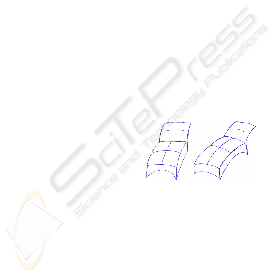
Figure 1: Our proposed approach uses line drawings like
these of a couch for the reconstruction of 3D models.
That it is reasonable to constrain the sketch com-
plexity to line drawings is showed by (Tovey et al.,
2003). They decomposed sketches in their differ-
ent elements (form lines, components, form-shading,
non-form shading) and identified the form lines as
most important for transporting an idea of a shape.
Line drawings like in Figure 1 consist primarily of
those lines and therefore should be adequate for in-
ferring 3D shapes.
Even with reduced sketch complexity many chal-
lenges have to be faced:
• Working with non-predetermined views, for us-
ing sketches as they are;
• Handling perspective imprecision, because
sketches from the styling phase generally lack
65
H. Wendt L., Stork A., Kuijper A. and Fellner D. (2010).
3D RECONSTRUCTION FROM LINE DRAWINGS.
In Proceedings of the International Conference on Computer Graphics Theory and Applications, pages 65-71
DOI: 10.5220/0002818600650071
Copyright
c
SciTePress

perspective correctness;
• Line drawings of arbitrary freeform objects give
little geometric cues about shape;
• Little and simple user interaction, so the system
is useable by non experts with little effort;
• Handling ambiguity, which arise when inferring
3D information from 2D.
2 RELATED WORK
Extensive research is done in imitating sketching pro-
cesses to interactively create 3D models. A compre-
hensive overview and taxonomy of interactive sketch-
based modeling is given in (Olsen et al., 2008) and
(Olsen et al., 2009). These methods are excellent
for creating 3D models in an easy an intuitively way,
but they seldom address the use of prior created hand
drawn sketches.
Dealing with this (Kara et al., 2006) presented an
interactive method for transferring the shape infor-
mation from a sketch to a template model. For this
purpose a scanned image of a sketch from a non-
predetermined viewpoint is used. The Template is
then aligned with this image in an easy way by inter-
actively drawing the virtual bounding box of the ob-
ject. While redrawing the form lines of the sketch, the
shape is transferred onto the 3D template. In a newer
work Kara and Shimada (Kara and Shimada, 2008)
use fiducial points for aligning the template with the
sketch and for template deformation. Those fiducial
points are given by the user for the sketch and corre-
spond to fiducial nodes of the template. The above
mentioned approaches have the benefit, that the user
does most of the interpretation and filtering of the
strokes in the sketches. So the approach itself does
not need to cope with the heterogeneity of the input
sketches. While this is a promising and applicable
approach, in the end the user redraws his sketch.
In contrast more direct reconstruction need to
cope with the heterogeneity of input sketches and
3D models. This often results in making restrictions
to sketches and 3D models. One of the first work,
which engages the direct reconstruction from a line
sketch was by Lipson and Shpitalni (Lipson and Sh-
pitalni, 1996). In their paper they present a method for
reconstructing a polyhedron from one orthographic
line drawing. The approach used geometric infor-
mation like parallelism and orthogonality of lines in
the sketches. This method is restricted to polyhe-
dra and does not support curved elements. (Varley
et al., 2004) propose a two stage approach where, the
user is asked to create a drawing of a curved object
and a corresponding polyhedron. In the first stage
the polyhedron is reconstructed and serves as tem-
plate. In the second stage the edges and surface are
deformed to match the drawing of the curved object,
so that a curved object is reconstructed. A method for
elements with planar curves is presented in (Masry
and Lipson, 2005). In this paper first the depths of
the vertices from the line drawing are determined by
checking the consistency with an underlying orthogo-
nal axis system. Planar curves are then reconstructed
by determining their plane equation by using an op-
timization function. According to the authors this al-
gorithm performs best on sketches that exhibit strong
orthogonal trends. Opposite to our approach, where
we not rely on orthogonality and aim for the recon-
struction of non-planar curves.
While the previous works used single views there
also exist approaches working with multiple sketches.
(Wang and Latif, 2003) proposed a method for in-
ferring a solid 3D model from engineering drawings,
therefore extruding 3D objects from the 2D sketches
and combining them using constructive solid geome-
try methods. Their approach is restricted to the or-
thographic front, side and top views. Zhang et al.
cover in (Zhang et al., 2004) the reconstruction of a
wireframe model consisting of conic curves. In their
work the views are restricted to the same three main
views. In contrast, we use perspective sketches from
arbitrary viewpoints.
Even though many different approaches for inter-
preting drawn sketches exist, to our knowledge, no
approach for reconstructing a 3D model, consisting
of curves, using perspective sketches with little user
interaction, has been presented so far.
3 OUR PROPOSED METHOD
We divide the reconstruction process into three main
stages (see also Figure 2). These stages will be cov-
ered more detailed in the following section.
The first stage is vectorization. In this stage we
convert the raster image to a suitable 2D representa-
tion of the sketch, which then will be used for the re-
construction. In this vectorization stage we convert
off-line scanned images into a network of 2D curves,
which are linear approximated. We use a rather sim-
ple vectorization algorithm, because we support only
line drawings. The vectorization stage is covered in
Section 4.
The second one is the actual 3D reconstruc-
tion process where the 2D information from multiple
sketches is combined to infer a 3D wireframe model.
To receive a transformation from 2D sketch space to
GRAPP 2010 - International Conference on Computer Graphics Theory and Applications
66
Vectorization
3D Reconstruction
Post-processing
2D network of curves
3D network of curves
Camera calibration
3D Node reconstruction
Shape reconstruction
3D edge graph
Generation of candidate nodes
Filtering of candidate nodes
Generation of 3D curves
Extrusion of 2D curves
Deformation of 3D curves
Sketches
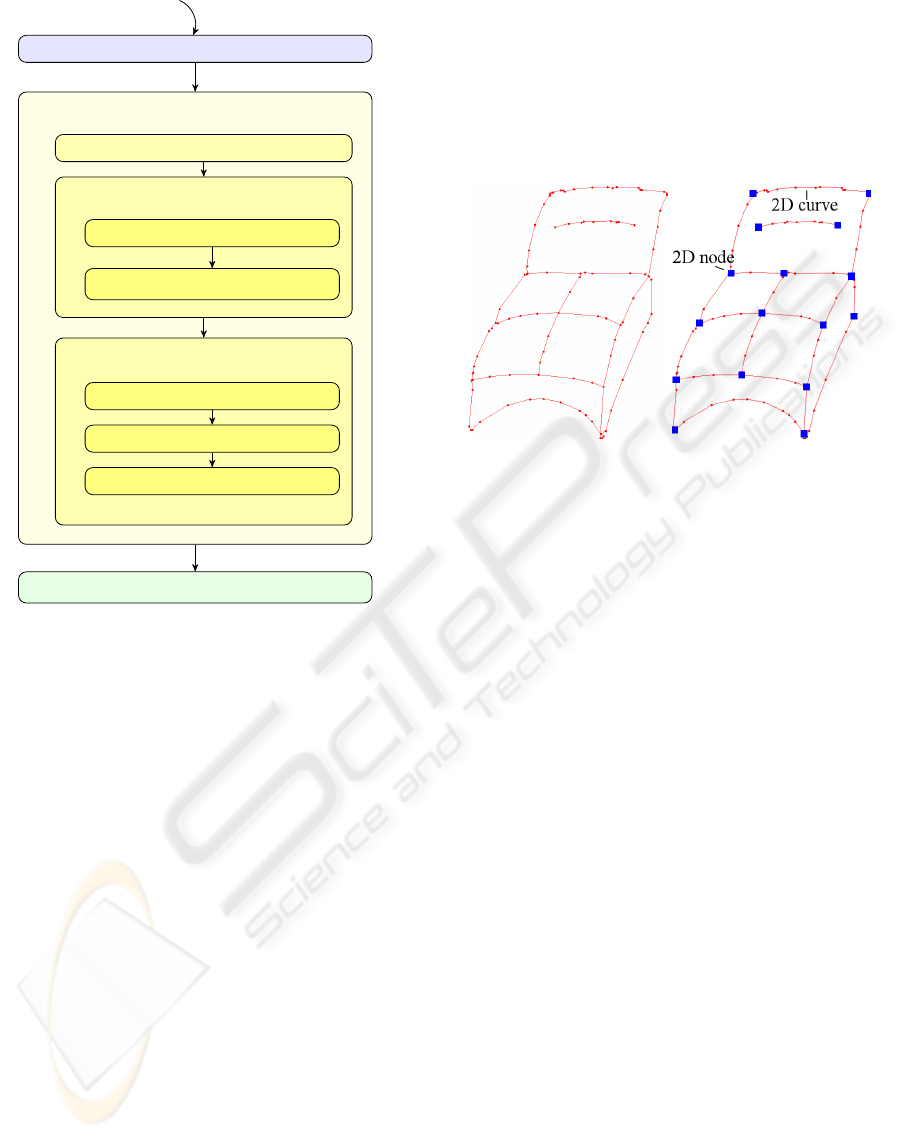
Figure 2: Our proposed algorithm is divided in three main
stages.
3D object space we utilize a virtual camera model.
Then we determine the 3D positions to the endpoints
of the curves resulting from the vectorization. For the
transfer to 3D we are using the estimated projection
matrix from the camera model and the connectivity
information of the 2D network. In the following step
we deform the edges in 3D to the shape inferred from
their correspondent 2D curves. For this purpose we
divide the edge in 3D in a set of linear segments. The
forming is done by extruding the 2D curves into 3D
space, thus creating a surface on which the edge is
fitted. Details are covered in Section 5.
The last stage is the post-process where the model
is visualized. The user has the possibility to modify
the model. Because we only reconstruct the visible
side of an object, the user can define a mirror plane to
extend symmetric objects. This is outlined in Section
6.
4 VECTORIZATION
To get a suitable representation, the sketch is vector-
ized to a network of linear line segments (Figure 3).
This will be converted into a network of curves, where
the crossings of the drawn lines are the nodes and the
drawn lines the curves.
Figure 3: On the left: The vectorization result of the left
sketch from Figure 1. The drawn curves are approximated
polygonally. On the right: The 2D nodes from the network
of curves.
The vectorization algorithm we use is intended
for grayscale line drawings with roughly uniform line
thickness and without shading, like the two examples
shown in Figure 1. This is done with the following
image processing methods:
• First the image is converted to in a binary image
using an adaptive threshold algorithm, dividing
the raster image in foreground and background.
• With the morphological erosion operation we re-
move small artifacts created through the scan-
ning and binarization process. With the dilation
operation we close gaps between strokes.
• In a last step of morphological operations the
drawing is skeletonized. This means the lines
are thinned to a minimum while keeping the end
points.
• The skeleton, which results is now segmented in
polylines approximating the drawn curve.
• In the final step we simplify the mesh by remov-
ing small dangling edges.
The vertices of the vectorization with a valency
higher or equal than three are considered as endpoints
of the curves. The path between two of these end-
points consist of linear edges and approximates the
drawn line polygonally. An example is shown in Fig-
ure 3. After this step the user can insert new nodes
and so additionally divide the curve. This is a use-
ful function, because in the following reconstruction
3D RECONSTRUCTION FROM LINE DRAWINGS
67
stage we receive better results when the topologies of
the networks of curves are similar.
5 3D RECONSTRUCTION
In the reconstruction stage we use multiple networks
of curves from the multiple sketches, for inferring a
network of 3D curves. This is done in three steps,
explained in the following sections.
5.1 Calibrating a Virtual Camera
For the calibration of a virtual camera model we pro-
ceed like previously described by Kara et al. in (Kara
et al., 2006). We first need a set of pairs (at least 6) of
correlating 2D and 3D points. These points we get
by letting the user draw the projection of a virtual
bounding box into the sketch (see Figure 4). With
the eight corner points of the bounding box and the
approximate dimensions of the object (also given by
the user). We calculate an estimated projection ma-
trix from 3D to 2D, their inverse and the position of
the virtual camera.
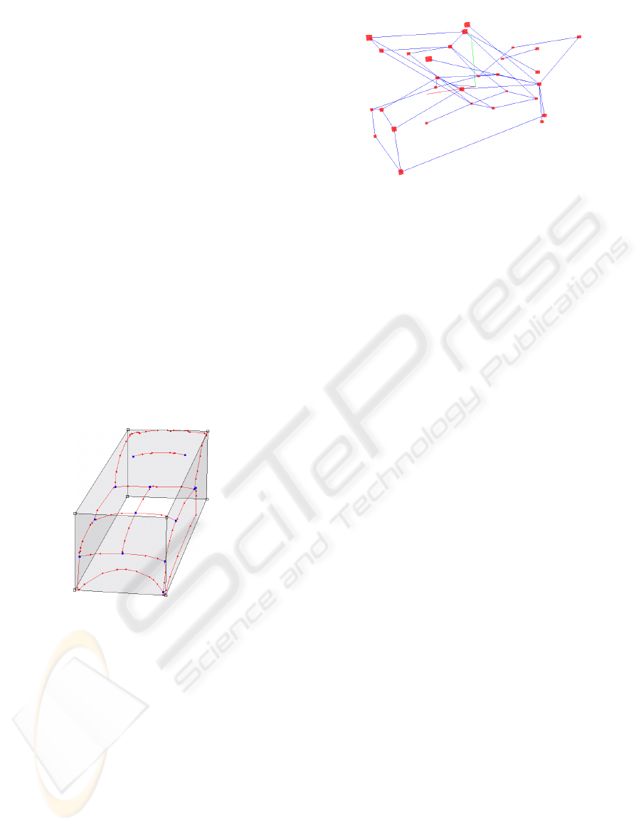
Figure 4: This figure shows a bounding box given by a user -
the corners of this box are used to calibrate a virtual camera.
5.2 Reconstruction of Nodes in 3D
In this step we aim to reconstruct points in 3D, which
serve later as nodes of a network of 3D curves.
First we generate candidate nodes. A candidate
node is a node in 3D, which has the chance to become
the reconstruction of a 2D node. For the construc-
tion of those candidates, we divide the 3D space into
a voxelgrid. For each voxel of that grid, we calclulate
the 2D projection in the several sketches and deter-
mine the nearest 2D node. These 2D nodes are saved
on the voxel as witnesses, which means that this 2D
node could support the creation of a 3D node in this
voxel. After this we examine the voxels with two or
more witnesses. This implies that our algorithm needs
object nodes to be visible in more than one sketch.
Figure 5: This picture shows the 3D candidate nodes gen-
erated from the two sketches shown in Figure 1. The edges
visualize the candidates connectivity inferred from the net-
works of 2D curves.
Observing the voxelspace, we now see that clouds
of voxels have evolved. These voxel clouds contain
voxels which share the same set of witnesses. They
are compressed to their center creating a point in 3D.
This point is candidate to be the 3D representative of
its witnesses and so a candidate to be a 3D node of
the reconstruction. In Figure 5 we see the resulting
candidate nodes. An edge between two candidates in-
dicates that those two nodes have witnesses, which
are connected by a drawn curve in a sketch.
To filter the candidate nodes, we make use of the
connectivity information in the network of 2D curves.
The candidates are added to the resulting 3D network
by a greedy algorithm, which adds the nodes by a rat-
ing. The rating we applied here, reflects how well
a candidate is connected in the 3D network. There-
fore, we calculate the sums of lengths of all paths,
which starts at the 3D candidate node. These paths
travel over the neighbor candidates, while only using
candidates with at least two witnesses, which were
not witnesses of candidates prior on the path. Is a
candidate added to the 3D network, its witnesses are
removed from the witness list of the remaining can-
didates. Therefore it is necessary to recalculate the
rating after each addition of a candidate to the 3D net-
work.
This approach guaranties that a 3D node has only
one 2D representative per sketch and a 2D node has
only one 3D representative. So we resolved the am-
biguity by using the heuristic of connectivity of the
2D nodes. Now, we have a 3D wireframe model with
linear edges. The next step is to reconstruct the shape
information for these edges.
5.3 Shape Reconstruction
The main idea behind the shape reconstruction step
is to deform the edges in 3D in such a way that they
conform to the 2D sketch.
GRAPP 2010 - International Conference on Computer Graphics Theory and Applications
68
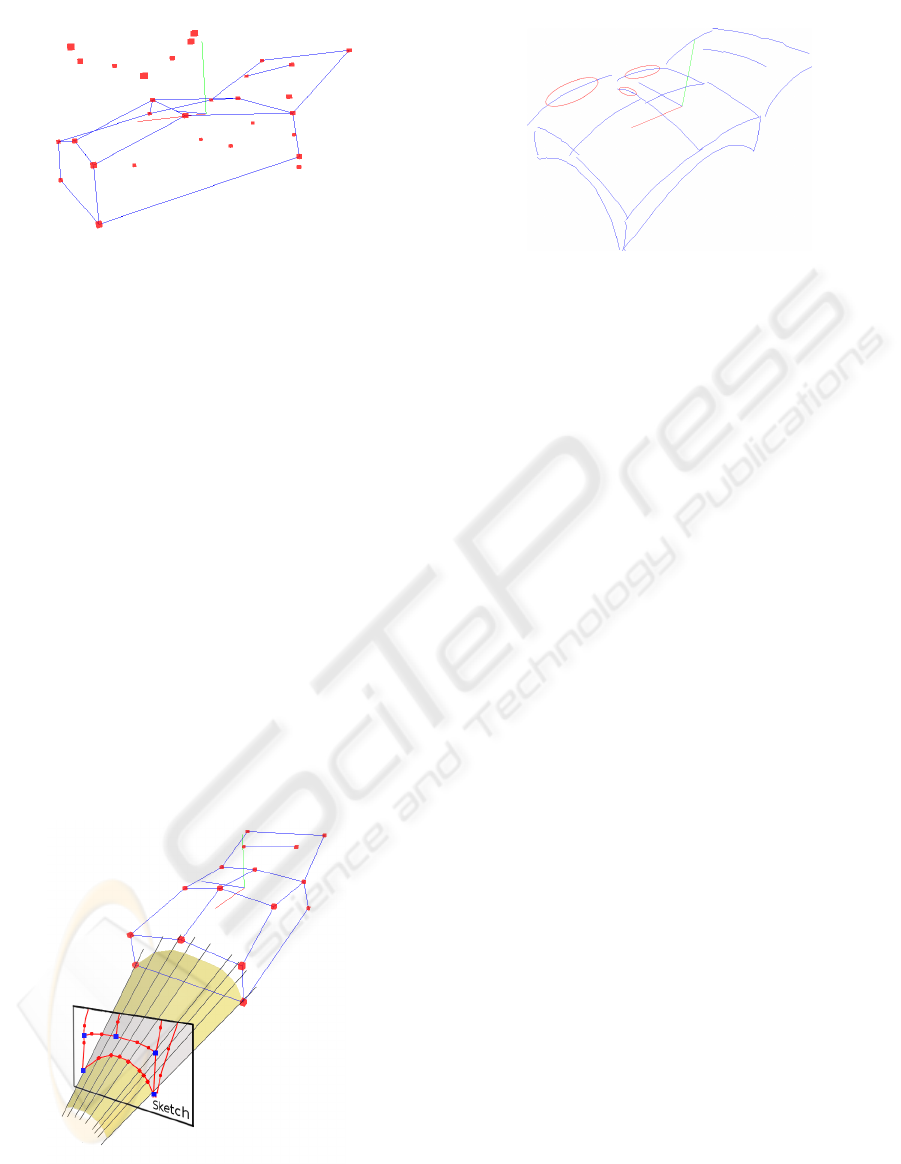
Figure 6: The candidate nodes are now filtered and only the
edges between the resulting 3D nodes remain. The candi-
dates in the picture which are not connected to the network
are those which are discarded.
First we generate a 3D curve for each recon-
structed edge in 3D. Polylines serve as approximation
for the 3D curves. They are created by dividing an
edge in equally spaced linear segments.
We transfer the 2D shape information to 3D by ex-
truding a surface from the corresponding 2D curve.
We know the corresponding 2D curves for each 3D
curve from the reconstruction step of the 3D Nodes.
For extruding the surface we use the inverse of the
projection matrix from Section 5.1. With this matrix
we determine the rays from the virtual camera center
through the vertices of the 2D curve. These rays fan
the surface, like in Figure 7.
Then we deform the 3D curve by projecting the
vertices of the 3D curve onto this surface. For this
purpose we calculate for each 3D vertex a correspond-
ing interval on the 2D curve. Then the vertex is moved
to its nearest point on the part of the surface created
by the determined interval. This will allow us to adapt
extreme curves.
Figure 7: The extrusion of a 2D curve leads to a surface,
which is used for shaping the 3D curve.
Since we are working with multiple sketches more
than one corresponding curve exists. It seems sug-
Figure 8: An example for reconstructed 3D shape informa-
tion is shown. The marked curves will be deleted by the
user when he mirrors the object in the post-processing step
(see Section 6).
gestive to use the shape information of at least two
curves. This resolves ambiguity, because the 3D
curve is then well defined by the intersection of two
extruded surfaces. We have implemented it by min-
imizing the distance of the 3D curve vertices to two
extruded surfaces. However, when the surfaces are
nearly parallel, the intersection prone to big devia-
tions in view direction. This is intensified by the in-
accuracy in the sketch and can lead to implausible
curves. In these cases best results were achieved by
using only one 2D curve. For this purpose, we want to
select the 2D curve which might give the best result.
So we use the longest 2D curve, under the assumption
that it contains better shape information than a shorter
one.
At this point we have a network of 3D curves like
the one showed in Figure 8.
6 POST-PROCESSING
The received 3D model from the previous section can
now be evaluated by the user. Many designed objects
are symmetric. Therefore, it seems sensible to give
the user at least the ability to extend the model by
adding the mirrored result. This gives the user a more
complete impression of the object. However, it can
lead to double curves, where curves are visible two
times in the sketch (e.g. on the near and the far side of
the object), like those marked in Figure 8. Some dou-
bled curves may be unwanted, stemming from impre-
cision or misinterpretation in the reconstruction. The
user has the possibilty to remove such curves at will.
3D RECONSTRUCTION FROM LINE DRAWINGS
69
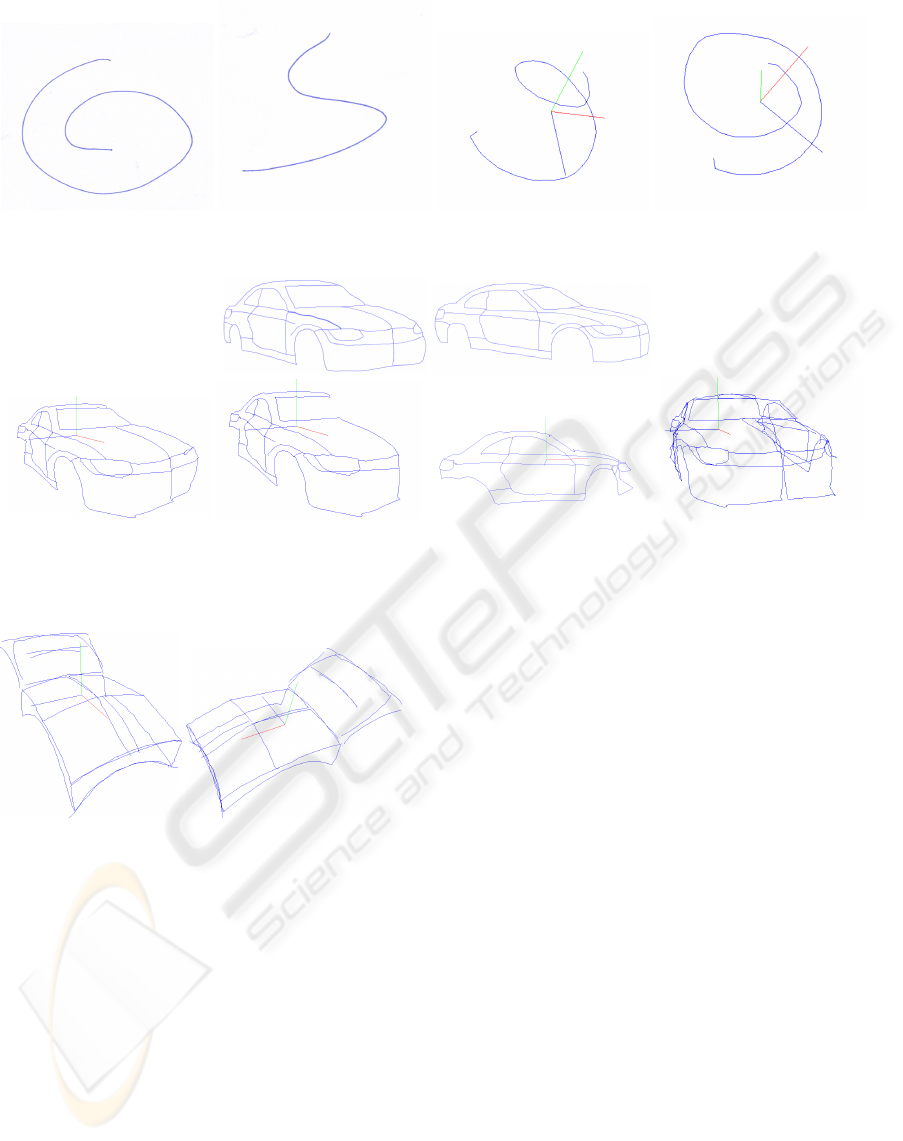
Figure 9: Result ”Spiral” a) Two line drawings of a 3D spiral on the left. One from top view the other from side view. b) The
reconstructed spiral in two views on the right. This shows that our method can reconstruct complex curves.
Figure 10: Result ”Car” a) Two line drawings of a car on top. b) On the left: The resulting 3D model with all reconstructed
and deformed edges. c) Second from left: the model without manually deleted edges as preparation for the mirroring. d)
Second from right: The side view on the model. e) On the right: A mirror plane was defined to extend the model.
Figure 11: Two views of the final result from the two
sketches shown in Figure 1 for the couch example.
7 RESULTS
We show the implementation results on sketches of
three different objects in Figures 11-10.
The couch example (result in Figure 11) accom-
panied us throughout the paper. It is a good example
for sketches that lack perspective precision. It also
contains a drawn line which is not connected to the
rest of the model but nonetheless has a plausible re-
construction. This example was mirrored in the post-
process and three curves (those marked in Figure 8)
were removed. In the pre-processing step four 2D
nodes where inserted in each sketch.
Another example - a sketch of a spiral (see Figure
9) - shows that our method is able to reconstruct non-
planar curves. This is true as long as the drawn curve
is not self-intersecting. On self-intersecting curves
our vectorization algorithm creates a 2D node which
makes a reconstruction more difficult.
The reconstruction of a complex model is shown
by an example of a car (see Figure 10). Here the
user inserted 2D nodes on the contour leading to a
more suitable segmentation of the curve. Furthermore
in the post-processing step the user has removed the
edges on the farther side of the symmetry plane and
mirrored the object.
The reconstruction stage took for all models only
few (2-5) seconds on a stand-alone PC, without the
time needed for camera calibration. The time needed
for interaction varied from 2 minutes (spiral, couch)
to 5 minutes (car). These durations cover all the in-
teraction (camera calibration, insertion of 2D nodes,
mirroring, removing 3D curves). We believe that
these timings are fast enough to justify further explo-
ration of the approach in a productive styling envi-
ronment. An obvious next step is to add surface re-
construction out of the 3D curves e.g. through Coons
patches.
GRAPP 2010 - International Conference on Computer Graphics Theory and Applications
70

8 CONCLUSIONS AND FUTURE
WORK
We have shown an approach for reconstructing a
3D model existing of curves from multiple but few
sketches. Only little user interaction is needed and
takes place in a pre- and post-processing step. In
the automated reconstruction process, we assume that
parts of an object, which should be reconstructed, are
present in at least two views with the same level of de-
tail. The sketches used, are perspective and show the
object from different not predetermined viewpoints.
Here the chosen voxel-based approach allows us to
handle perspective imprecision of the sketches to a
certain degree.With such features this method could
be part of a system to evaluate first styling concepts.
However we want to do more evaluations of the
system with regard to user effort and robustness. A
further object of special attention is handling silhou-
ette lines. Silhouettes in sketches convey important
shape information. However the handling is difficult,
because they are varying from view to view. Another
focus of our future work is to utilize robust vector-
ization approaches like (Hilaire and Tombre, 2006)
so we can use sketches containing more complex-to-
handle content such as shading.
ACKNOWLEDGEMENTS
We want to thank the reviewers for helpful advises
and corrections. For the implementation of this work
we used the Open Source Libraries OpenCV, QGar
and OpenSG. This work is partially supported by the
European projects 3D-COFORM (FP7-ICT-2007.4.3-
231809) and FOCUS K3D (FP7-ICT-2007-214993).
REFERENCES
Hilaire, X. and Tombre, K. (2006). Robust and Accu-
rate Vectorization of Line Drawings. IEEE Transac-
tions on Pattern Analysis and Machine Intelligence,
28(6):890–904.
Kara, L. B., D’Eramo, C. M., and Shimada, K. (2006). Pen-
based styling design of 3D geometry using concept
sketches and template models. In SPM ’06: Proceed-
ings of the 2006 ACM symposium on Solid and phys-
ical modeling, pages 149–160, New York, NY, USA.
ACM.
Kara, L. B. and Shimada, K. (2008). Supporting early
styling design of automobiles using sketch-based 3D
shape construction. Computer-Aided Design and Ap-
plications, 5(6):867–876.
Lipson, H. and Shpitalni, M. (1996). Optimization-based
reconstruction of a 3D object from a single freehand
line drawing. Computer-aided Design, 28(8):651–
663.
Masry, M. and Lipson, H. (2005). A Sketch-Based Interface
for Iterative Design and Analysis of 3D Objects . In
Jorge, J. A. P. and Igarashi, T., editors, Eurographics
Workshop on Sketch-Based Interfaces and Modeling,
pages 109–118, Dublin, Ireland. Eurographics Asso-
ciation.
Olsen, L., Samavati, F., Sousa, M. C., and Jorge, J. A.
(2009). Sketch-based modeling: A survey. Computers
& Graphics, 33(1):85–103.
Olsen, L., Samavati, F. F., Sousa, M. C., and Jorge, J.
(2008). A Taxonomy of Modeling Techniques using
Sketch-Based Interfaces . In Theoharis, T. and Dutre,
P., editors, Eurographics 2008 - State of the Art Re-
ports, pages 39–57, Crete, Greece. Eurographics As-
sociation.
Tovey, M., Newman, R., and Porter, S. (2003). Sketching,
concept development and automotive. Design studies,
24:135–153.
Varley, P. A. C., Takahashi, Y., Mitani, J., and Suzuki, H.
(2004). A Two-Stage Approach for Interpreting Line
Drawings of Curved Objects . In Jorge, J. A. P., Galin,
E., and Hughes, J. F., editors, Sketch-Based Interfaces
and Modeling, pages 117–126, Grenoble, France. Eu-
rographics Association.
Wang, Z. and Latif, M. (2003). Reconstruction of a 3D solid
model from orthographic projections. In Proceedings
of the 2003 International Conference on Geometric
Modeling and Graphics (CMAG’03), pages 75–82.
Zhang, A., Xue, Y., Sun, X., Hu, Y., Luo, Y., Wang, Y.,
Zhong, S., Wang, J., Tang, J., and Cai, G. (2004). Re-
construction of 3D curvilinear wireframe model from
2D orthographic views. In Computational Science -
ICCS 2004, volume 3037 of Lecture Notes in Com-
puter Science, pages 404–411. Springer Berlin / Hei-
delberg.
3D RECONSTRUCTION FROM LINE DRAWINGS
71
