
MANIPULATION OF PARAMETRIC SURFACES THROUGH A
SIMPLE DEFORMATION ALGORITHM
L. H. You
1
, H. Ugail
2
, X. Y. You
3
, E. Chaudhry
1
and Jian J. Zhang
1
1
National Centre for Computer Animation, Bournemouth University, U.K.
2
School of Computing, Informatics and Media, University of Bradford, U.K.
3
Faculty of Engineering and Computing, Coventry University, U.K.
Keywords: Surface Manipulation, Partial Differential Equation, Approximate Analytical Solution.
Abstract: In this paper, we present a novel but simple physics based method to manipulate parametric surfaces. This
method can deal with local deformations with an arbitrarily complicated boundary shape. We firstly map a
deformation region of a 3D surface to a circle on a 2D parametric plane. Then we derive an approximate
analytical solution of a set of fourth order partial differential equations subjected to sculpting forces and the
boundary conditions of the circle. With the obtained solution, we show how to create a deformed surface
and how sculpting forces and the shape control parameters affect the shape of a deformed surface. Finally,
we provide some examples to demonstrate the applications of our proposed method in surface manipulation.
1 INTRODUCTION
Surface manipulation is at the heart of geometric
modelling and has attracted a lot of research
attention.
Depending on whether physics of object
deformation is introduced or not, surface
manipulation can be divided into purely geometric
and physics based. Purely geometric surface
manipulation achieves the intended shapes by
manually changing the positions of surface points or
control points. Physics based surface manipulation
obtains different surface shapes by applying virtual
forces to deform the surfaces.
Directly manipulating surface points of
polygonal models or control points of NURBS
models is a commonly used method for purely
geometric surface manipulation. In addition,
extrusion, blending, sweeping, skinning, filleting,
chamfering, and Boolean operations etc. are also
frequently applied in shape manipulation (Fleming
1999; Maestri 1999).
In order to improve the efficiency and capability
of surface manipulation, free from deformation
methods were developed. By simulating the
deformations caused by twisting, bending, tapering,
or similar transformations of geometric objects, Barr
(1984) proposed new operations for shape
manipulation. Following Barr’s work, Sederberg and
Parry (1986) developed a more general approach
called free-form deformation (FFD). This method
embeds an object in a lattice and achieves the
deformations of the object by deforming the lattice.
By using the initial lattice points to define an
arbitrary trivariate Bézier volume, and allowing the
combination of many lattices to form arbitrarily
shaped spaces, Coquillart (1990, 1991) introduced
Extended Free-Form Deformations (EFFD). Free-
form deformation was also investigated by
Lamousin and Waggenspack (1994), MacCracken
(1996), Hirota et al. (2000), and Feng et al. (2002,
2006).
Purely geometric surface manipulation methods
are simpler and more efficient than the physics
based methods. However, purely geometric methods
do not follow any underlying physical laws.
Therefore, if an object is to be modelled by such
methods, the quality depends on the skills and
perception of modellers. For a same object, different
modellers may create somewhat different shapes.
This issue may be resolved by introducing the
underlying physics governing the deformation of
deformable materials. The surface manipulation
based on this consideration is called physics based.
It considers material properties and physical laws
relevant to surface deformation. This approach has a
potential to create more realistic looking objects.
Employing the elasticity theory, Terzopoulos and
his colleagues (1987) and (1988) introduced
dynamic differential equations for flexible materials
84
H. You L., Ugail H., Y. You X., Chaudhry E. and J. Zhang J. (2010).
MANIPULATION OF PARAMETRIC SURFACES THROUGH A SIMPLE DEFORMATION ALGORITHM.
In Proceedings of the International Conference on Computer Graphics Theory and Applications, pages 84-89
DOI: 10.5220/0002823100840089
Copyright
c
SciTePress

such as rubber, cloth and paper. This work was
extended from elasticity to viscoelasticity, plasticity
and fracture (Terzopoulos and Fleischer 1988). By
minimizing the energy functional under user
controlled geometric constraints and loads, Celniker
and Gossard (1991) presented a curve and surface
finite element method for shape manipulation. Based
on a primal formulation and a hybrid formulation
derived from the theory of pure elasticity, Güdükbay
and Özgüç (1994) investigated a physically based
modeling algorithm to animate deformable objects.
In order to deal with mass distributions, internal
deformation energies, and other physical quantities
of shape manipulation of NURBS, a dynamic
NURBS was developed by Terzopoulos and Qin
(1994). This method was further investigated to
tackle the surfaces with symmetries and topological
variability which leads to a dynamic NURBS swung
surface (Qin and Terzopoulos 1995). By extending
triangular B-splines to triangular NURBS and using
Lagrangian mechanics, Qin and Terzopoulos (1997)
developed the mathematical model of dynamic
triangular NURBS and manipulated the surfaces
defined over arbitrary, nonrectangular domains
through the finite element solution of the
mathematical model. Applying sculpting forces on a
surface and formulating and minimizing the energy
functional of the surface, Vassilev (1997) proposed a
method to manipulate deformable B-spline surfaces.
Using the model of a bar network, Léon and Veron
(1997) and Guillet and Léon (1998) dealt with the
deformation of free-form surfaces. Considering non-
homogeneous material properties and conducting the
finite element calculations of deformable objects in
local frames, McDonnell and Qin (2007) presented a
new, physics based shape manipulation method.
Surfaces can also be described by the solution to
a partial differential equation subjected to suitably
defined boundary conditions. Partial differential
equations (PDEs) based modelling was first
introduced by Bloor and Wilson (1989, 1990). In
order to cope with more complicated surface
modelling problems, Bloor and Wilson proposed a
spectral approximation method (1996) and a
perturbation method (2000). Using the partial
differential equation (PDE) method, Ugail et al.
(1999) examined how practical surfaces can be
constructed interactively in real time. Kubeisa et al.
(2004) addressed the problem of interactive design
of higher order PDEs. In the work carried out by
Ugail (2004), the generation of the spline of a PDE
surface and parameterization of the surface by using
the spline were investigated. By studying the so-
called harmonic and biharmonic Bézier surfaces,
Monterde and Ugail (2004) presented a new method
of surface generation. By defining the trim curves to
be a set of boundary conditions, Ugail (2006)
proposed a method to trim PDE surfaces. How
Bézier surfaces can be generated from boundary
information through a general 4th-order PDE was
tackled by Monterde and Ugail (2006). Generalizing
the governing partial differential equation to
arbitrary order, complex shapes were designed as
single patch by Ugail (2007). Incorporating dynamic
effects into a fourth order PDE, You and Zhang
studied creation of 3D deformable moving surfaces
(2003). Using a sixth order PDE and a semi-
analytical and semi-numerical solution, Zhang and
You (2004) presented a method for surface
modelling.
This paper will focus on surface manipulation
using an approximate analytical solution to fourth
order partial differential equations. It maps an
arbitrary deformation region in 3D coordinate space
to a circle in 2D parametric plane, achieves the
approximate analytical solution of the deformation
within the circle, and uses it to manipulate surfaces.
2 MATHEMATICAL MODEL
The deformations of a surface can be simulated
through those of a thin elastic plate. When subjected
a lateral load
q , the mathematical model describing
surface deformations is
),,(
2
4
4
22
4
4
4
zyx
D
q
vvuu
(1)
subjected to the following boundary conditions
),,(
0 ,0 ,0
zyx
vu
(2)
where
)1(12
2
3
Eh
D
(3)
and
E
and
are Young’s modulus and Poisson’s
ratio, and
h is the thickness of a surface.
3 SOLUTION
Since the analytical solution of Eq. (1) under the
MANIPULATION OF PARAMETRIC SURFACES THROUGH A SIMPLE DEFORMATION ALGORITHM
85
boundary conditions (2) on a circular boundary is
obtainable, we take the boundary defined by
parametric variables
u and v to be
01
22
vu
(4)
For the deformation which has both positional
and tangential continuities at boundary (2), we take
the following functions as the solution of Eq. (1)
),,(
)1(
222
zyx
vum
(5)
where
m is an unknown constant.
Substituting Eq. (5) into (2), boundary conditions
are satisfied exactly.
Substituting Eq. (5) into (1), we determine the
unknown constant
m and obtain the analytical
solution of Eq. (1).
4 APPLICATIONS
In order to use the above method to determine the
deformations of a 3D surface, we relate a
deformation region with an arbitrary boundary shape
to a circle.
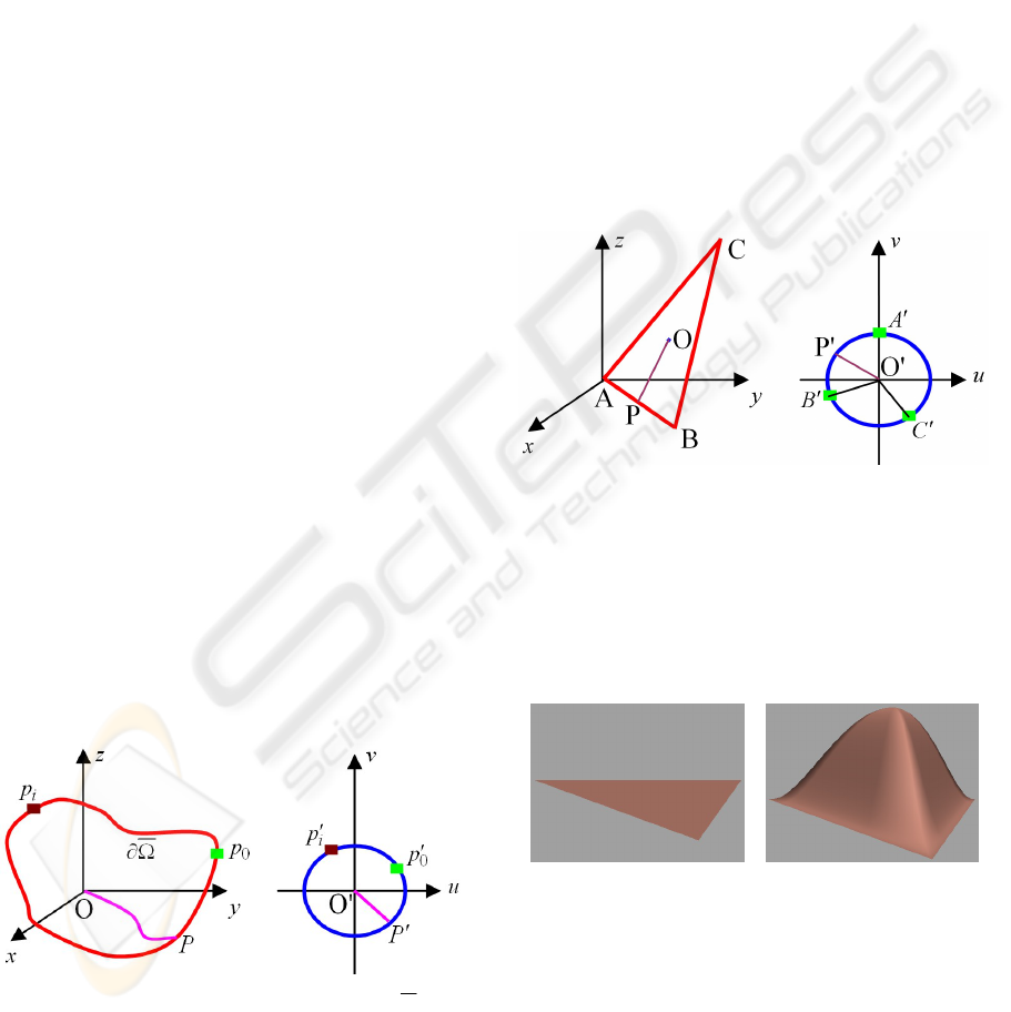
As shown in Figure 1, we use the length of the
boundary of the deformation region and the circle to
determine the corresponding points
P
and
P
between them. Then, we find a point
O on the 3D
surface which corresponds to the geometric centre of
the deformation region. The surface curve
OP is
related to the straight line
PO
. With such a
treatment, we obtain the one-to-one relationship
between all the points on the 3D surface and those
within the circle.
Figure 1: Parameterization of boundary
and
deformation region.
Finally, we apply a sculpting force
q , and use
the above method to calculate the deformations of
the 3D surface, and superimpose these deformations
to the original surface to create the deformed
surface. In the subsections below, we will
demonstrate this through a number of examples.
4.1 Surface Deformations within a
Triangle
In this subsection, we investigate how to deform a
triangle.
As indicated in Figure 2, by calculating the
length of the triangle and the circle, we find the
points
A
, B
and C
on the circle which correspond
to the three vertices A, B and C of the triangle,
respectively.
Then we calculate the geometric centre
O of the
triangle from its three vertices. This geometric
centre
O is related to the centre O
of the circle.
Figure 2: Parameterization of a triangle.
For an arbitrary point
P
on the boundary of the
triangle, we find its corresponding point
P
on the
circle. The points on the line
OP are related to the
points on the line
PO
. The same method is used to
determine the one-to-one relationship of the points
between the triangle and the circle.
a b
Figure 3: Surface deformation within a triangle region.
For a triangle deformation region indicated in
Figure 3a, we set Young’s modulus
10000E ,
Poisson’s ratio
3.0
, surface thickness 1.0
h
and the sculpting force
100
z
q . The deformation of
the triangle was obtained and depicted in Figure 3b.
GRAPP 2010 - International Conference on Computer Graphics Theory and Applications
86
4.2 Effect of Material and Geometric
Properties
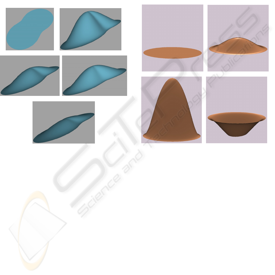
In this subsection, we examine how material and
geometric properties affect the shape of a surface.
The deformation region in a 3D coordinate space
was shown in Figure 4a. It was mapped into a circle.
Basic parameters are taken to be: the material
properties
10000E , 3.0
, geometric property
1.0h , and sculpting force 100
z
q .
a b
c d
e
Figure 4: Effect of material and geometric properties.
The deformed surface indicated in Figure 4b was
obtained. Only raising Young’s modulus to 20000
and keeping all other basic parameters unchanged,
the deformation was reduced and the deformed
shape in Figure 4c was generated. When Poisson’s
ratio of the basic parameters was increased to 0.6,
the deformation given in Figure 4b was dropped to
that in Figure 4d. Increasing the surface thickness to
0.15 also decreases the deformation and produces
the shape in Figure 4e.
4.3 Effect of Sculpting Forces
Here we study how sculpting forces affect surface
deformations. The deformation region in a 3D
coordinate space is an ellipse. The original surface
shape within the ellipse is depicted in Figure 5a. The
surface will be deformed in
z
direction. Young’s
modulus E is taken to be
30000E , Poisson’s ratio
is set to
3.0
. Applying a sculpting force 50
z
q
on the surface, the surface was pulled upwards and
the deformed shape was indicated in Figure 5b.
Raising the sculpting force to 200, the deformation
was greatly increased as indicated in Figure 5c.
Changing both the direction and size of the sculpting
force, i. e., setting the sculpting force to -120, the
surface was push downwards and the deformed
shape in Figure 5d was created. These images
indicate that sculpting forces are very useful in
surface manipulation.
a b
c d
Figure 5: Effect of sculpting force.
4.4 Local Deformations
In this subsection, we discuss how to use our
proposed method to achieve complex local
deformations of 3D models.
For a 3D surface model, we first interactively
specify the region which will be deformed. Then we
extract the boundary curve of the deformation
region. Finally, the above method is used to
determine the corresponding relationship between
the deformation region and a circle.
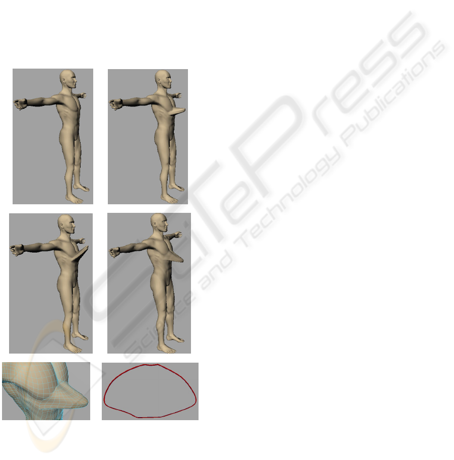
Here we give an example to deform a male chest.
The undeformed chest was shown in Figure 6a. The
boundary of the deformation region on the chest was
shown in Figure 6f. By applying different sculpting
forces to the deformation region, different deformed
shapes were obtained and depicted in Figures 6b, 6c
and 6d. A local view of the deformation shape in
Figure 6b was given in Figure 6e.
MANIPULATION OF PARAMETRIC SURFACES THROUGH A SIMPLE DEFORMATION ALGORITHM
87
5 CONCLUSIONS
A physics based surface manipulation method has
been proposed through the above work. For doing
this, we examined the relationship between a
deformation region in 3D coordinate space and a
circle in 2D parametric plane and formulated the
corresponding boundary conditions. By constructing
proper trial functions, we obtained an approximate
analytical solution which exactly satisfies both
positional and tangential continuities at the circle
and the partial differential equations. With the
application examples given in this paper, we
discussed how to use the solution to carry out
surface manipulation.
a b
c d
e f
Figure 6: Deformation of a male chest.
The method proposed in this paper can be easily
developed into an interactive software tool whereby
surface manipulation can be performed easily and in
real-time. We intend to develop such a tool in the
future.
REFERENCES
Fleming, B., 1999. 3D Modeling & Surfacing, Academic
Press.
Maestri, G., 1999.
Digital Character Animation, Volume
1: Essential Techniques
, New Riders Publishing.
Barr, A. H., 1984. Global and Local Deformations of Solid
Primitives,
Proceedings of SIGGRAPH ’84 and
Computer Graphics 18(3)
, 21-30.
Sederberg, T.W., Parry, S.R., 1986. Free-Form
Deformation of Solid Geometric Models,
Proceedings
of SIGGRAPH ’86 and Computer Graphics 20(4)
,
151-159.
Coquillart, S., 1990. Extended free-form deformation: a
sculpturing tool for 3D geometric modelling,
In
Computer Graphics (SIGGRAPH ’90 Proceedings) 24
,
187-196.
Coquillart, S., Janc´ene, P., 1991. Animated free-form
deformation: An interactive animation technique,
In
Computer Graphics (SIGGRAPH ’91 Proceedings) 25
,
23–26.
Lamousin, H., Waggenspack, W., 1994. NURBS-based
free-form deformation,
IEEE Computer Graphics and
Applications 14(6)
, 59-65.
MacCracken, R., 1996. Free-from deformations with
lattices of arbitrary topology,
In Proceedings of the
23
rd
Annual Conference on Computer Graphics and
Interactive Applications (SIGGRAPH 96)
, 181-188.
Hirota, G., Maheshwari, R., Lin, M.C., 2000. Fast volume-
preserving free-form deformation using multi-level
optimization,
Computer-Aided Design 32(8), 499-
512(14).
Feng, J., Nishita, T., Jin, X., Peng, Q., 2002. B-spline free-
form deformation of polygonal object as trimmed
Bézier surfaces,
The Visual Computer 18, 493-510.
Feng, J., Shao, J., Jin, X., Peng, Q., Forrest, A.R., 2006.
Multiresolution free-form deformation with
subdivision surface of arbitrary topology,
The visual
Computer 22(1)
, 28-42.
Terzopoulos, D., Platt, J., Barr, A., Fleischer, K., 1987.
Elastically deformable models,
Computer Graphics
21(4)
, 205-214.
Terzopoulos, D., Fleischer, K., 1988. Deformable models,
The Visual Computer 4, 306-331.
Terzopoulos, D., Fleischer, K., 1988. Modeling inelastic
deformation: viscoelasticity, plasticity, fracture,
Computer Graphics 22(4), 269-278.
Celniker, G., Gossard, D., 1991. Deformable curve and
surface finite-elements for free-form shape design,
Computer Graphics 25(4), 257-266.
Güdükbay, U., Özgüç, B., 1994. Animation of deformable
models,
Computer-Aided Design 26(12), 868-875.
Terzopoulos, D., Qin, H., 1994. Dynamic NURBS with
geometric constraints for interactive sculpting,
ACM
Transactions on Graphics 13(2)
, 103-136.
Qin, H., Terzopoulos, D., 1995. Dynamic NURBS swung
surfaces for physical-based shape design,
Computer-
Aided Design 27(2)
, 111-127.
Qin, H., Terzopoulos, D., 1997. Triangular NURBS and
their dynamic generations,
Computer Aided Geometric
GRAPP 2010 - International Conference on Computer Graphics Theory and Applications
88

Design 14, 325-347.
Vassilev, T. I., 1997. Interactive sculpting with
deformable nonuniform B-splines,
Computer Graphics
Forum 16
, 191-199.
Léon, J. C., Veron, P., 1997. Semiglobal deformation and
correction of free-form surfaces using a mechanical
alternative,
The Visual Computer 13, 109-126.
Guillet, S., Léon, J. C., 1998. Parametrically deformed
free-form surfaces as part of a variational model,
Computer-Aided Design 30(8), 621-630.
Mandal, C., Qin, H., Vemuri, B.C., 2000. Dynamic
modeling of butterfly subdivision surfaces,
IEEE
Transactions on Visualization and Computer Graphics
6(3)
, 265-287.
McDonnell, K. T., Qin, H., 2007. A novel framework for
physically based sculpting and animation of free-form
solids,
The Visual Computer 23(4), 285-296.
Bloor, M. I. G., Wilson, M. J., 1989. Generating blend
surfaces using partial differential equations,
Computer-Aided Design 21(3), 165-171.
Bloor, M. I. G., Wilson, M. J., 1990. Using partial
differential equations to generate free-form surfaces,
Computer-Aided Design 22(4), 202-212.
Bloor, M. I. G., Wilson, M. J., 1996. Spectral
approximations to PDE surfaces,
Computer-Aided
Design 28(2)
, 145-152.
Bloor, M. I. G., Wilson, M. J., Mulligan, S. J., 2000.
Generating blend surfaces using a perturbation
method,
Mathematical and Computer Modelling
31(1)
, 1-13.
Ugail, H., Bloor, M. I. G., Wilson, M. J., 1999.
Techniques for Interactive Design Using the PDE
Method,
ACM Transactions on Graphics 18(2), 195-
212.
Kubiesa, S., Ugail, H., Wilson, M. J., 2004. Interactive
design using higher order PDEs,
The Visual Computer
20
, 682-693.
Ugail, H., 2004. Spine based shape parameterisation for
PDE surfaces,
Computing 72, 195-206.
Monterde, J., Ugail, H., 2004. On harmonic and
biharmonic Bézier surfaces,
Computer Aided
Geometric Design 21(7)
, 697-715.
Ugail, H., 2006. Method of Trimming PDE Surfaces,
Computers & Graphics 30(2), 225-232.
Monterde, J., Ugail, H., 2006. A General 4th-Order PDE
Method to Generate Bézier Surfaces from the
Boundary,
Computer Aided Geometric Design 23(2),
208-225.
Ugail, H., 2007. Generalized Partial Differential Equations
for Interactive Design, International
Journal of Shape
Modeling 13(2)
, 225-226.
You, L. H., Zhang, J. J., 2003. Fast Generation of 3D
Deformable Moving Surfaces,
IEEE Transactions on
Systems, Man and Cybernetics, Part B: Cybernetics
33(4)
, 616-625.
Zhang, J. J., You, L. H., 2004. Fast surface modelling
using a 6
th
order PDE, Computer Graphics Forum
23(3)
, 311-320.
MANIPULATION OF PARAMETRIC SURFACES THROUGH A SIMPLE DEFORMATION ALGORITHM
89
