
ON-LINE PLANAR AREA SEGMENTATION FROM SEQUENCE OF
MONOCULAR MONOCHROME IMAGES FOR VISUAL
NAVIGATION OF AUTONOMOUS ROBOT
Ohnishi Naoya, Yoshihiko Mochizuki
Graduate School of Advanced Inteligence Science, Chiba University, Japan
Atsushi Imiya, Tomoya Sakai
IMIT, Chiba University, Japan
Keywords:
Variational image analysis, Fractional differentiation, Optical flow.
Abstract:
We introduce an on-line segmentation of a planar area from a sequence of images for visual navigation of
a robot. We assume that the robot moves autonomously in a man-made environment without any stored
map in the memory or any markers in the environment. Since the robot moves in a man-made environment,
we can assume that the robot workspace is a collection of spatial plane segments. The robot is needed to
separate a ground plane from an image and/or images captured by imaging system mounted on the robot. The
ground plane defines a collision-free space for navigation. We develop a strategy for computing the navigation
direction using a hierarchical expression of plane segments in the workspace. The robot is required to extract
a spatial hierarchy of plane segments from images. We propose an algorithm for plane segmentation using an
optical flow field captured by an uncalibrated moving camera.
1 INTRODUCTION
Spatial reasoning is a fundamental process for vi-
sual navigation and localisation of autonomousrobots
(Kuipers and Byun, 1991; Wagner et al., 2004). Seg-
mentation of image is a fundamental problem in im-
age understanding. Segmentation is categorised in su-
pervised and unsupervised method. In this paper, we
deal with unsupervised on-line segmentation for vi-
sual navigation of a robot. Assuming that the robot
moves on a planar ground plane, the robot is needed to
separate a ground plane from an image and/or images
captured by imaging system mounted on the robot.
Segmentation is a methodology to extract mean-
ingful parts from a image and a video sequence. As
a human-interface tool for editing images on a com-
puter screen, marker-based semi-supervised and su-
pervised segmentation techniques are studied. Apow-
erful method used as a back-end of the method is
graph cut. For visual navigation, the robot required
to use unsupervised on-line segmentation algorithm.
Therefore, the robot cannot use marker-based seg-
mentation method. Furthermore, the most impor-
tant segment on an image is a free-space on which
the robot can navigate without colliding to obstacles.
The ground plane defines a collision-free space for
navigation. Therefore, we introduce a visual navi-
gation algorithm for a robot which moves in a man-
made indoor environment. In a man-made environ-
ment planer surface on polyhedral objects are domi-
nant geometrical features. Therefore, configurations
of planer segments are essential quarry for obstacles.
Assuming that a robot is deriving on a flat plane with
polyhedral obstacles, we develop a method to hier-
archically separate planar segments in a scene us-
ing an image sequence captured by a imaging sys-
tem mounted on the robot. Since a robot moves, the
imaging system mounted on the robot automatically
captures a sequence of images. This series of images
derives optical flow sequence. The depth of planer
segment affects to the observed optical flow. There-
fore, the robot can separate planar areas based on the
depths from the camera on the robot. We assume that
for the collision free navigation a robot decide the di-
rection to tern using the configurations of planes in
front of the robot.
Model-based methods for image segmentation
have been proposed. Homography-based methods
435
Ohnishi N., Mochizuki Y., Imiya A. and Sakai T. (2010).
ON-LINE PLANAR AREA SEGMENTATION FROM SEQUENCE OF MONOCULAR MONOCHROME IMAGES FOR VISUAL NAVIGATION OF
AUTONOMOUS ROBOT.
In Proceedings of the International Conference on Computer Vision Theory and Applications, pages 435-442
DOI: 10.5220/0002825404350442
Copyright
c
SciTePress

(Chum et al., 2005; Yang et al., 2005) use plane-to-
plane homography for detecting a plane. Motion seg-
mentation with layers is proposed in refs. (Wang and
Adelson, 1994; Weiss, 1997). Brox et al. proposed
an algorithm for image segmentation by the level set
method (Brox et al., 2006). We use the dominant-
plane model for segmenting multiple planar areas.
Since the dominant plane is a planar area in the robot
workspace and it corresponds to the largest part of an
image, our algorithm does not require any restrictions
on the camera motion or geometric configurations be-
tween the camera and objects. The hierarchical detec-
tion of dominant planes allows the robot to achieve
spatial reasoning without any three-dimensional re-
construction of the scene, since the dominant plane
is a binary feature on the image plane. Furthermore,
since the dominant plane is a binary feature, the algo-
rithm is robust against the outliers that are derived in
the process of optical-flow computation.
2 DOMINANT PLANE AND
OPTICAL FLOW
2.1 Dominant Plane
We define the dominant plane in an image.
Definition 1 . The dominant plane as the planar area
in the robot workspace corresponding to the largest
part of an image or at least the half of an image.
Similarly with the previous paper (N.Ohnishi
and Imiya, 2005), we accept the following five
assumptions.
Assumptions
1. The ground plane is the planar area.
2. The camera mounted on the mobile robot is look-
ing downward.
3. The robot observes the world using the camera
mounted on itself for navigation.
4. The camera on the robot captures a sequence of
images since the robot is moving.
5. Obstacles occupy at most 1/2 region in an image
captured by the robot.
Therefore, if there are no obstacles around the robot,
and since the robot does not touch the obstacles, the
ground plane corresponds to the dominant plane in the
image observed through the camera mounted on the
mobile robot. Assuming that the dominant plane in
the image corresponds to the ground plane on which
the robot moves, the detection of the dominant plane
enables the robot to detect the feasible region for nav-
igation in its workspace.
2.2 Optical Flow on the Dominant Plane
Assuming that the camera displacement is small, on
each layer the corresponding points x = (x,y)
⊤
and
x
′
= (x
′
,y
′
)
⊤
in the dominant planes between a pair
of successive two images are connected with an affine
transform such that x
′
= Ax + b, where A and b are
a 2× 2 affine-coefficient matrix and a 2-dimensional
vector.
We can estimate the affine coefficients using
the RANSAC-based algorithm (Fischler and Bolles,
1981). Using estimated affine coefficients, we can es-
timate optical flow on the dominant plane ˆx = ( ˆx, ˆy)
⊤
,
ˆx = Ax +b −x, for all points x in the image. We call
ˆx the planar flow on the lth layer , and ˆx = (x, y,t)
the planar flow field at time t, which is a set of planar
flow ˆx computed for all pixels in an image.
If an obstacle exists in front of the robot, the pla-
nar flow on the image plane differs from the optical
flow on the image plane. Since the planar flow vector
ˆx is equal to the optical flow vector ˙x on the dominant
plane, we use the difference between these two flows
to detect the dominant plane. We set ε to be the toler-
ance of the difference between the optical flow vector
and the planar flow vector. Therefore, for the optical
flow equation ∇I
⊤
˙x + ∂
t
I = 0 of an image I observed
at time t if the inequality
| ˙x − ˆx| < ε,
s.t. ˆx = (Ax + b)− x, ∇I
⊤
˙x + ∂
t
I = 0 (1)
is satisfied, we accept point x as a point on the domi-
nant plane (N.Ohnishi and Imiya, 2005).
Our algorithm is summarised as follows:
1. Compute optical flow field u(x,y,t) from two suc-
cessive images.
2. Compute affine coefficients of the transform Ax +
bby random selection of three points.
3. Estimate planar flow field ˆu(x,y,t) from affine co-
efficients.
4. Match the computed optical flow field u(x,y,t)
and estimated planar flow field ˆu(x
l
,y
l
,t) using
eq. (1).
5. Assign the points | ˙x − ˆx| < ε as the dominant
plane. If the dominant plane occupies less than
half the image, then return to step 2.
6. Output the dominant plane d(x,y,t) as a binary
image.
VISAPP 2010 - International Conference on Computer Vision Theory and Applications
436
2.3 Hierarchical Plane Segmentation
Using the dominant-plane-detection algorithm itera-
tively, we develop an algorithm for multiple-plane
segmentation in an image.
Our basic algorithm detects the dominant plane in
an image. After removingthe region correspondingto
the dominant plane from the image, we can extract the
second dominant planar region from the image. Since
the first dominant plane is assumed to be the ground
plane, the second dominant plane corresponds to an
obstacle. Then it is possible to extract the third dom-
inant plane by removing the second dominant planar
area. This process is expressed as
D
k
=
A(R\ D
k−1
), k ≥ 2,
A(R), k = 1,
(2)
where A, R, and D
k
stand for the dominant-plane-
extraction algorithm, the region of interest observed
by the camera, and the kth dominant planar area, re-
spectively. The algorithm is stopped after a predeter-
mined iteration time or when the size of the kth dom-
inant plane is smaller than a predetermined size.
The iterative plane-segmentation algorithm is
summarised as follows:
Algorithm 1: Hierarchical Segmentation.
repeat
if the dominant plane cannot be detected
then stop;
Remove the dominant plane area from the
image;
until predetermined number of times K ;
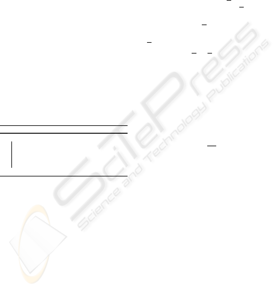
The procedure of the algorithm is shown in Fig. 1. In
the experiments, we set the predetermined number of
the iteration K in algorithm 4 as K = 3.
Setting R to be the root of the tree, this yields de-
rives a binary tree such that
RhD
1
,R\ D
1
hD
2
,R
2
\ D
2
h··· ,ii. (3)
Assuming that D
1
is the ground plane on which the
robot moves, D
k
for k ≥ 2 correspond the planar ar-
eas on the obstacles. Therefore, this tree expresses
the hierarchical structure of planar areas on the ob-
stacles. We call this tree the binary tree of planes.
Using this tree constructed with the dominant-plane-
detection algorithm, we obtain the topological config-
uration of planes in an image. Even if an object exists
in an image and it lies on D
k
, k ≥ 2, the robot can
navigate while ignoring this object, using the binary
tree of planes, as shown in Fig. 2. In accordance with
the spatial configuration of planar areas, the robot can
decide the navigation direction.
3 SPATIAL REASONING USING
HIERARCHY OF PLANE
SEGMENTS
In this section, we apply an algorithm based on the
extension of eqs. (2) and (3) to the spatial reasoning
used for the robot navigation.
For an image R
2
, setting D and D to be the dom-
inant plane area in R
2
and its conjugate D = R
2
\ D,
respectively, we have the tree structure
R
2
hD,Di. (4)
Applying the dominant-plane-detection algorithm
to D, we have the tree structure
R
2
hD,DhD
1
,D
1
ii. (5)
Here, we affix the labels L, R, and M to these trees,
where L, R, and M express the locations of the domi-
nant plane in the hierarchy on the image plane. From
the property of the dominant plane clarified in section
2.1, we have the following tree structures from the hi-
erarchical extraction of the dominant planes. These
structures are derived from the geometrical configu-
ration of obstacles in workspace from a sequence of
images captured with a camera mounted on the robot.
We have the possibilities
T
L
= R
2
hD
L
,D
R
hD
RL
,D
RR
ii, (6)
T
M
= R
2
hD
M
,D
M
i, (7)
T
R
= R
2
hD
L
hD
LL
,D
LR
i,D
R
i (8)
T
D
=
/
0. (9)
Equation (9) means that no dominant plane in front of
the robot exists, which is shown as property in sec-
tion 2.1. Therefore, these three trees correspond to
spatial configurations of planes in front of the robot,
as shown in Fig. 4. The correspondence between
the trees and spatial configurations indicates the di-
rection of collision-free paths for the mobile robot. In
accordance with these trees, which express the con-
figurations of the free space and obstacles in front of
the robot, the mobile robot decides which direction to
move. For the robot to move on the dominant plane
without colliding with obstacles, the rule of the robot
motion is as follows.
These trees describe the following four geometri-
cal configurations.
1. Obstacles and the free space for the robot to move
exist in the left and right, respectively. Therefore,
the robot should move to the right.
2. Obstacles and the free space for the robot to move
exist in the right and left, respectively. Therefore,
the robot should move to the left.
ON-LINE PLANAR AREA SEGMENTATION FROM SEQUENCE OF MONOCULAR MONOCHROME IMAGES
FOR VISUAL NAVIGATION OF AUTONOMOUS ROBOT
437
3. The free space for the robot to move exists in front
of the robot. Therefore, the robot can move for-
ward.
4. Obstacles exist in front of the robot. Therefore,
the robot should turn 180 degrees to move to the
backward.
Algorithm 2: Obstacle Avoidance Rule.
if T(t) = T
L
(t) then
the robot turns to the left;
t := t + 1;
else if T(t) = T
R
(t) then
the robot turns to the right;
t := t + 1;
else
T(t) = T
M
(t);
the robot moves forward;
t := t + 1;
end
else
T(t) = T
D
(t);
the robot turns 180 degrees;
t := t + 1;
end
While the robot is moving, it obtains the sequence
of trees T(t) such that
T(t) = T
M
,
T(t + 1) = T
M
,
T(t + 2) = T
R
, (10)
T(t + 3) = T
R
,
.
.
. .
When the robot detects the transition of trees, that is,
T(t + 1) 6= T(t), (11)
the robot is required to control its direction for navi-
gation. This property is used to derive the control rule
as follows.
Algorithm 3: Direction Control Rule.
if T(t) = T(t − 1) then
the robot moves in the direction of the label
of T
∗
(t − 1);
else
the robot moves in the direction of the label
of T
∗
(t);
t := t + 1;
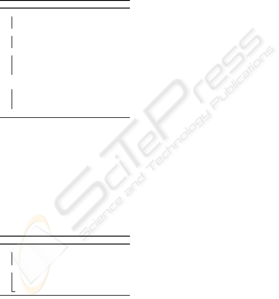
Using the labels of the trees, this rule is expressed
as the automaton given in Fig. 3. The label of the cell
corresponds the direction in which the robot moves.
The automaton accepts the binary tree corresponding
to the spatial configuration of the dominant plane.
We show an experimental example of mobile
robot navigation using a hierarchy of plane segments.
The specifications of the mobile robot used for this
experiment are summarised in Table 1. In the experi-
ments, the mobile robot moves in a room. If the mo-
bile robot detects a wall, it turns to the left or right
in accordance with the binary tree computed from the
spatial configuration of planar areas. The control rule
is described in the previous section.
The results in Fig. 14 and property 2 described
in section 2.1 show that the robot would turn and re-
turn to the start point if there are many obstacles be-
tween the start point and destination. Therefore, we
prepared the environments with the sparse configura-
tion of obstacles. For the experiments in the real envi-
ronment, on the basis of property 2 derived in section
2.1, we prepared four scenarios for the experiments.
Obstacle Configuration of Experiments
E.1 Wall Following. The robot moves following the
walls of the man-made room. In this experiment,
the robot was required to compute the positions to
start turning and to stop turning using a sequence
of trees extracted from an image sequence using
optical-flow technique.
E.2 Corridor Passing. In this experiment, the robot
was required to achieve centring in the corridor
using a sequence of trees extracted from an im-
age sequence using optical-flow technique. Since
the robot, at present, does not numerically com-
pute the configuration of the obstacles, the corri-
dor width is to be the twice of the width of the
robot. The robot is required to estimate the cor-
ridor centre using topological information derived
as a sequence of trees
E.3 Random Box. Some boxes of the same size as the
robot are randomly and sparsely distributed in the
workspace. There is a corridor path in front of the
robot.
E.4 Door Closing. A student closed the door to the
corridor on the straight path in front of the robot.
The closing of the door causes the transition of
the obstacle configuration in the workspace and
the map of the workspace. Therefore, this sce-
nario provides a dynamic environment in the robot
workspace.
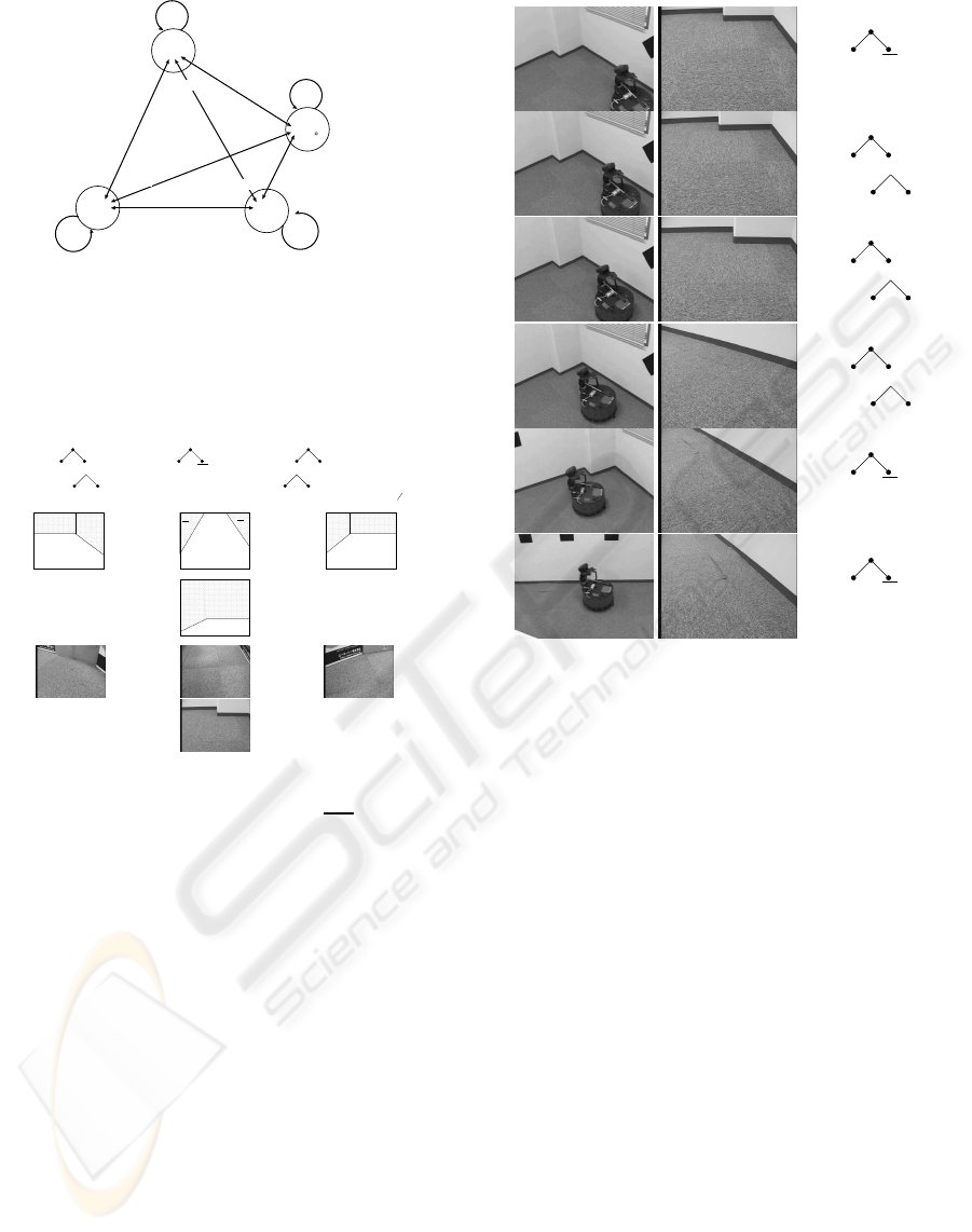
For the first scenario, we show all the snapshots,
views from the robot, and the trees extracted from
these images. The experimental result for mobile
robot navigation using the hierarchy of plane seg-
ments is shown in Fig. 5. Snapshots of the mobile
robot, images captured by the mobile robot and binary
trees extracted from these images are shown. Using
VISAPP 2010 - International Conference on Computer Vision Theory and Applications
438
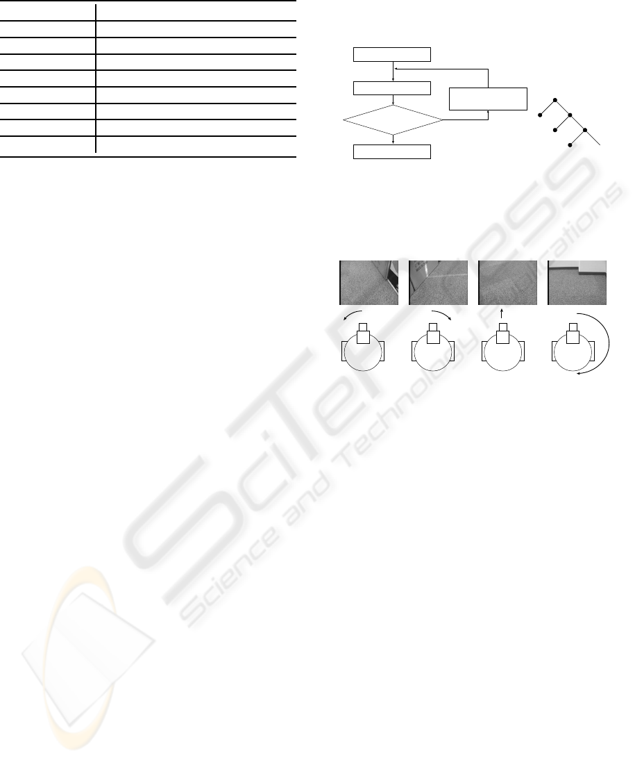
Table 1: Specifications of our mobile robot.
Name Magellan Pro, AAI Systems, Inc.
Size Circular - 16-inch diameter
Weight 50pounds
Drive 2-wheel
CPU 800MHz, AMD-K6 processor
Main memory 256MB
OS Red Hat Linux
Compiler GNU C++ Compiler
Camera SONY EVI-D30
the sequence of these trees, we obtain the control se-
quence hM L L L Mi from this image sequence. The
left row of Fig. 5 shows the robot navigating by this
sequence of directions. This example shows that the
hierarchy of plane segments is acceptable as a cue for
mobile robot navigation.
In the practical experiments, the velocity of the
robot was approximately 5cm/s. The robot au-
tonomously moved in the room in our lab without col-
liding with obstacles and walls using the algorithms
described in the previous section.
Figure 6 shows snapshots of the corridor passing
of the robot without optical and geometrical calibra-
tion. The width of the corridor is approximately twice
of the width of the robot. The robot started from the
outside of the corridor and passed through the corri-
dor centre without colliding with the corridor walls.
Therefore, the camera configuration on our robot al-
lows the collision-free navigation if the width of the
corridor is at least twice the width of the robot.
Figure 7 shows a sparse-obstacle environment. In
this environment, although the obstacles are as large
as the robot, there is a corridor path in front of the
robot. Therefore, the robot detects a free space to pass
and decides a straight path to move in front of the
robot.
Figure 8 shows a dynamic environment. The door
to the corridor is closed by a student while robot is
moving to the door. Furthermore, the student returned
to the outside of the view field of the robot. After the
door is closed, the robot recognises the door as a part
of the wall and decides the path to the left. Since our
robot does not use any maps of the workspace, the
robot detects the wall in front of the robot and decides
the navigation direction to avoid the colliding with the
wall.
As described in section 3, our assumption on the
configuration of the obstacles is that the robot should
observe the first dominant plane as the free space on
the ground floor. The configurations for real experi-
ments satisfy this assumption. Therefore, as an exten-
sion of the featureless visual navigation introduced in
our previous paper (N.Ohnishi and Imiya, 2005), the
hierarchical expression of dominant planes yields the
control information for the navigation direction.
Dominant-plane detection
Dominant plane is detected?
Remove the dominant plane
from the image
Yes
End
Begin
R
D1
D2
D3
...
Figure 1: Extraction binary hierarchy of plane segments.
(a)Iterative plane-segmentation algorithm using dominant-
plane detection. (b) Binary tree extracted from hierarchical
structure of planar areas. R is the root of the tree and D
k
are
planes on the image.
Turn to left Turn to right Move forward Turn 180-degree
Figure 2: The configuration of planes determines the robot
motion. The top row shows examples of the patterns of
plane configurations captured by the camera mounted on
the robot. The bottom row shows the robot motion corre-
sponding to each plane configuration observed by the cam-
era mounted on the robot.
4 CONCLUSIONS
In the previous papers (Fermin and Imiya, 1997;
Imiya and Fermin, 1999), we developed a RANSAC-
based motion analysis algorithm for two- and three-
dimensional motions, respectively. Furthermore,
we developed a RANSAC-based free space analy-
sis method for visual navigation of the autonomous
robot, using a dominant-plane-detection strategy
(N.Ohnishi and Imiya, 2005). The dominant-
plane-based navigation method (Ohnishi and Imiya,
2006) detects the free space from the appearance of
the workspace using images captured by the cam-
era/cameras mounted on the robot. The method used
the mathematical relation between optical flow com-
puted from a series of images captured by a camera
mounted on the robot and homography transform be-
tween captured ground plane in a series of images.
In this paper, we extended these RANSAC-based
results to spatial reasoning to derive the navigation
ON-LINE PLANAR AREA SEGMENTATION FROM SEQUENCE OF MONOCULAR MONOCHROME IMAGES
FOR VISUAL NAVIGATION OF AUTONOMOUS ROBOT
439
Move
Forward
T(t)=TM
T(t)=TL
T(t)=TR
T(t)=TD
Turn
Left
Turn
Right
Turn
180
T(t)=T(t-1)
T(t)=T(t-1)
T(t)=T(t-1)T(t)=T(t-1)
Figure 3: Automaton for the direction control rule. The
labels of the cells show the directions in which the robot
moves. The automaton accepts the sequence of binary trees
corresponding to the spatial configuration of the dominant
plane. The state of the automaton changes in accordance
with Algorithms 5 and 6.
R
2
D
R
D
RL
D
RL
D
L
T
L
=
R
2
D
M
D
M
T
M
=
R
2
D
R
D
LL
D
LR
D
L
T
R
=
T
D
= O
R
2
D
R
D
RL
D
RR
D
L
R
2
D
M
D
M
D
M
R
2
D
R
D
LL
D
LR
D
L
R
2
Figure 4: Binary trees and corresponding images of hierar-
chical structure of dominant planes. R
2
is an image plane
and D
∗
are hierarchical dominant planes. D
M
= R
2
\ D
M
and
/
0.
direction in the visual navigation process. We extend
the dominant-plane detection to planer-area detection
in an image using the same property between opti-
cal flow and the homography transform of the planar
area in the workspace. For the extraction of planes,
we apply the dominant-plane detection algorithm hi-
erarchically to an image. This series of hierarchically
extracted planes expresses configurations of planar ar-
eas in the workspace. We can extract the second dom-
inant plane from the obstacle area, and the third dom-
inant plane from the obstacle area to the second dom-
inant plane. This set theory property of the dominant
planes enables us to define the higher order dominant
planes which describe the appearance configurations
of planer segments in the space. These plane config-
urations allow the extraction of the corridors for the
robot in the polygonal world.
The camera geometry of the imaging system
mounted on the robot is uncalibrated, that is, for the
R
2
D
M
D
M
T
M
=
R
2
D
R
D
RL
D
RL
D
L
T
L
=
R
2
D
R
D
RL
D
RL
D
L
T
L
=
R
2
D
R
D
RL
D
RL
D
L
T
L
=
R
2
D
M
D
M
T
M
=
R
2
D
M
D
M
T
M
=
Figure 5: Experimental result for mobile robot navigation
using hierarchy of plane segments. The left, middle, and
right columns show snapshots of the mobile robot, images
captured by the robot, and corresponding binary trees, re-
spectively. This example shows that the hierarchy of plane
segments is acceptable as a cue for describing the spatial
configuration of planar areas in front of the robot for mo-
bile robot navigation.
spatial reasoning of the navigation direction, the robot
does not use any parameters in the imaging system
and the robot. For the detection of the widths of the
corridors and the sizes of the obstacles, we are re-
quired to calibrate the imaging system of the robot
geometrically, since for geometrical reconstruction of
three-dimensional geometric configuration, geometri-
cal information such that the height of the camera cen-
tre from the ground plane, the downward angle of the
optical axis of the camera, the view-angle of camera,
the focal-length of the camera, the distance between
optical centre of the camera and gravity centre of the
robot are used(Young-Geun and Hakil, 2004). There-
fore, although our robot cannot calculate the sizes of
obstacles and the widths of corridors from images, the
robot can decide the configurations of obstacles and
corridors from the images. We assume that the widths
of the corridors in the workspace are sufficient for the
robot to pass through, since we are interested in spa-
tial reasoning for the direction control for robot nav-
igation. Our experiments showed that the navigation
VISAPP 2010 - International Conference on Computer Vision Theory and Applications
440
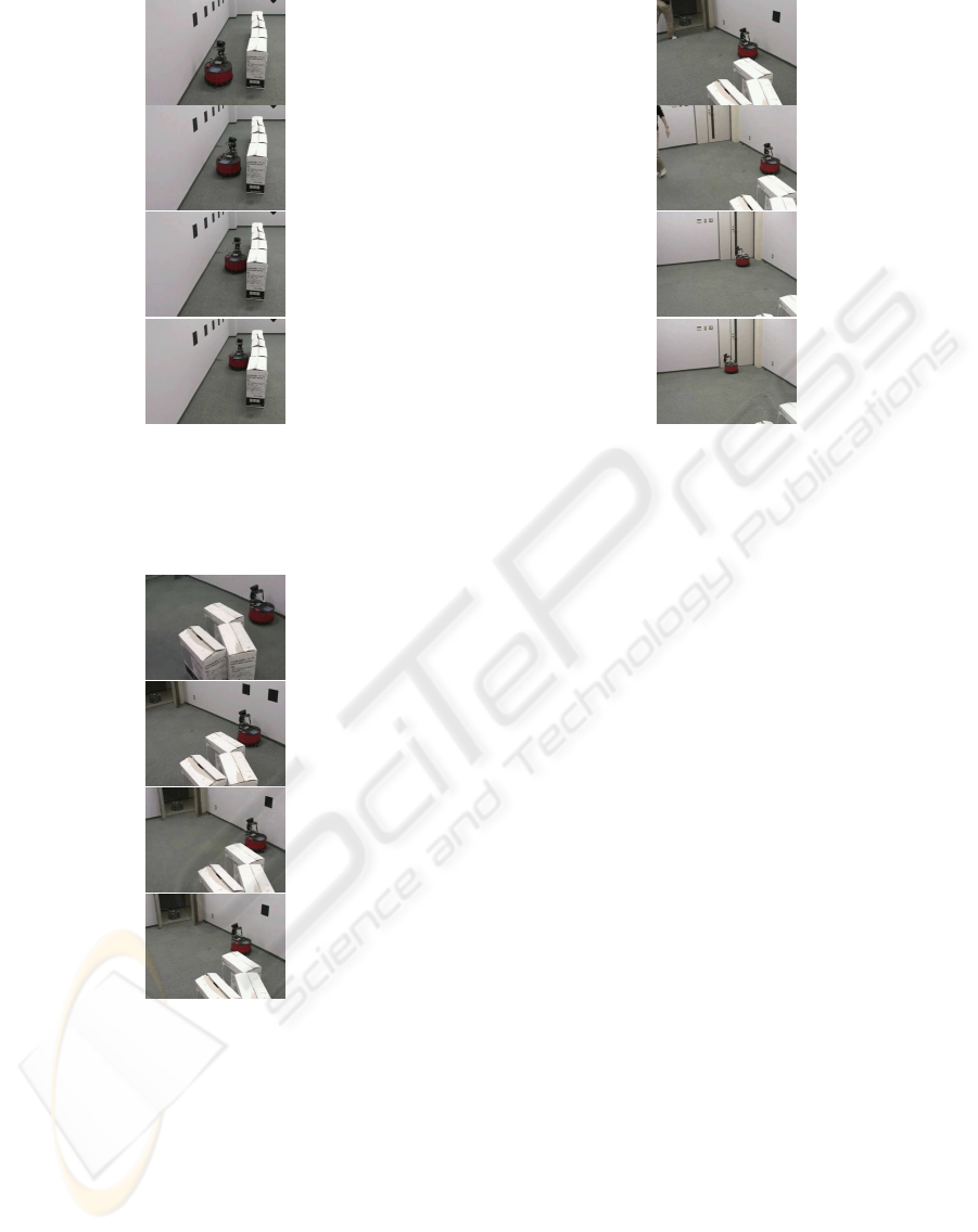
Figure 6: Experimental result for mobile robot naviga-
tion using hierarchy of plane segments. The robot passes
through the corridor, whose width is about the twice of the
width of the robot, without collision to the wall of the cor-
ridor.
Figure 7: A sparse real environment. Although obstacles
are large, the robot decides a straight path in a sparse envi-
ronment.
direction is computed using the topologicalconfigura-
tion of the ground floor and obstacles in the front view
of the robot captured by the imaging system mounted
on the robot.
Appearance-based object recognition is a stable
and robust method of volumetric shape recognition
from a series of images (Murase and Nayar, 1995).
The method is introduced to robotics (Jones et al.,
1997; Ulrich and Nourbakhsh, 2000). Applying the
appearance-based method to the localisation of the
Figure 8: A dynamic environment. After the door to the
corridor is closed , the robot recognises that the door is a
part of wall and find a path to the left.
mobile robot, Jones, Andresen, and Crowley (Jones
et al., 1997; Ulrich and Nourbakhsh, 2000) devel-
oped a method to achieve the localisation of the robot
from images without three-dimensional reconstruc-
tion of the spatial positions of the objects from an
image sequence. The appearance-based method al-
lows the acquisition of spatial features from images
without reconstructing the spatial locations of objects
in the space. The algorithm which we developed in
this paper is an algorithm for robot navigation without
reconstructing the three-dimensional locations of ob-
stacles and landmarks in the workspace. In this sense,
our algorithm can be categorised as an appearance-
based navigation strategy.
The appearance-based navigation is suitable for
the small-payload robot, since the method enables the
robot to navigate without any maps in the memory and
special purpose procedures for the landmark extrac-
tion. In applications, the combination of the prepath
planning and landmark-based localisation allows the
stable, robust and safe navigation of the robot. As
shown in a real experiment, our method allows the
robot to navigate autonomously even if the configu-
ration of the obstacles in the workspace is changed.
In the experiment, the transition of geometric config-
uration of obstacles in workspace is caused by clos-
ing the door to the corridor. Furthermore, a student,
who is an obstacle to the robot, walked to the door to
close it and returned from the view field of the camera
mounted on the robot. This control property is suit-
able for the collaboration of the robot with human be-
ings, since the motion of the human causes the tenta-
tive transition of configuration of the obstacles, which
ON-LINE PLANAR AREA SEGMENTATION FROM SEQUENCE OF MONOCULAR MONOCHROME IMAGES
FOR VISUAL NAVIGATION OF AUTONOMOUS ROBOT
441

is not described in the original map on the workspace.
Psychologically, it is known that the optical-flow
field is a basic cue for the understanding of motion
(Vaina et al., 2004). Our results also suggest that the
optical-flow field is a cue for determining the obstacle
configuration in a workspace.
REFERENCES
Brox, T., Bruhn, A., and Weickert, J. (2006). Varia-
tional motion segmentation with level sets. Proc.
ECCV2006, 1:471–483.
Chum, O., Werner, T., and Matas, J. (2005). Two-view
geometry estimation unaffected by a dominant plane.
CVPR05, 1:772–779.
Fermin, I. and Imiya, A. (1997). Planar motion detection by
randomized triangle matching. Pattern Recognition,
18:741–749.
Fischler, M. A. and Bolles, R. C. (1981). Random sample
consensus: A paradigm for model fitting with appli-
cations to image analysis and automated cartography.
Comm. of the ACM, 24:381–395.
Imiya, A. and Fermin, I. (1999). Motion analysis by random
sampling and voting process. CVIU, 73:309–328.
Jones, S. D., Andresen, C., and Crowley, J. L. (1997).
Appearance based processes for visual navigation.
IEEE/RSJ International Conference on Intelligent
Robots and Systems, 1:551–557.
Kuipers, B. and Byun, Y.-T. (1991). A robot exploration
and mapping strategy based on a semantic hierarchy
of spatial representations. Robotics and Autonomous
Systems, 8:47–63.
Murase, H. and Nayar, S. K. (1995). Visual learning and
recognition of 3-d objects from appearance. IJCV,
14:5–24.
N.Ohnishi and Imiya, A. (2005). Featureless robot naviga-
tion using optical flow. Connection Science, 17:23–
46.
Ohnishi, N. and Imiya, A. (2006). Dominant plane detec-
tion from optical flow for robot navigation. Pattern
Recognition Letters, 27:1009–1021.
Ulrich, I. and Nourbakhsh, I. (2000). Appearance-
based place recognition for topological localization.
ICRA2000, 1:1023–1029.
Vaina, L. M., Beardsley, S. A., and Rushton, S. K. (2004).
Optic Flow and Beyond. Kluwer, Amsteldam.
Wagner, T., Visser, U., and Herzog, O. (2004). Egocentric
qualitative spatial knowledge representation for physi-
cal robots. Robotics and Autonomous Systems, 49:25–
42.
Wang, J. Y. A. and Adelson, E. H. (1994). Representing
moving images with layers. IEEE Trans. on Image
Processing Special Issue: Image Sequence Compres-
sion, 3:625–638.
Weiss, Y. (1997). Smoothness in layers: Motion seg-
mentation using nonparametric mixture estimation.
CVPR97, 1:520–527.
Yang, A. Y., Rao, S., Wagner, A., and Ma, Y. (2005). Seg-
mentation of a piece-wise planar scene from perspec-
tive images. CVPR05, 1:154–161.
Young-Geun, K. and Hakil, K. (2004). Layered ground
floor detection for vision-based mobile robot naviga-
tion. ICRA04, 1:13–18.
VISAPP 2010 - International Conference on Computer Vision Theory and Applications
442
