
RELIABLE LOCALIZATION AND MAP BUILDING BASED ON
VISUAL ODOMETRY AND EGO MOTION MODEL IN
DYNAMIC ENVIRONMENT
Pangyu Jeong and Sergiu Nedevschi
Technical University of Cluj-Napoca, Baritu 28, Cluj-Napoca, Romania
Keywords: Visual Odometry (VO), Ego Motion Model, Ego Motion Control, Localization, Map Building, Temporal
Filter.
Abstract: This paper presents a robust method for localization and map building in dynamic environment. The
proposed localization and map building provide general approaches to use them both in indoor and outdoor
environments. The proposed localization is based on the relative global position starting from initial
departure position. In order to provide reliable positioning information, Visual Odometry (VO) is used
instead of ego robot’s encoder. Unlike general VO based localization, the proposed VO does not use
iterative refinement in order to select inliers. The suggested VO uses ego motion model based on the motion
control. The rotation and translation values of tracked features are guided by the estimated rotation and
translation values obtained by motion control. Namely the estimated motion provides upper and lower limits
of motion variation of VO. This estimated boundary of motion variation helps to reject outliers among
tracked features. The rejected outliers represent tracked features of fast/slow moving objects against ego
robot movement. The map is built along with ego robot path. In order to get rich 3D points in each frame
accumulated dense map based temporal filter method is adapted.
1 INTRODUCTION
The stable and accurate position estimation is a key
issue of the robot/vehicle navigation. The related
researchers have proposed absolute/relative global
position estimation. They have used GPS and INS
(Inertial Navigation System) to estimate
robot/vehicle position. Recently vision based new
approaches have been introduced for localization.
They have been called Visual Odometry (VO). The
VO provides stable position and rotation estimation
comparing with Encoder raw data.
Nister(2004) gives one of the first solutions for
Visual Odometry. He presents implementation
results using single camera and stereo camera in
order to estimate vehicle pose. He uses a feature
tracking method and the 5 point algorithm with
RANSAC to select the motion model in both single
camera and stereo camera. The result of Visual
Odometry is compared to result of INS/DGPS.
Howard(2008) presents a different approach to
Visual Odometry. Features tracked only in two
consecutive frames are triangulated to obtain 3D
points that are used in Visual Odometry. For
computing the rotation and translation parameters, a
back projection equation connecting the 3D tracked
points from the previous frame with the
corresponding 2D image points from the current
frame is optimized. The algorithm is verified
outdoor on many different robot platforms.
Agrawal(2007)
presents Visual Odometry in
rough terrain environment. They track features in
multiple frames rather than just in two consecutive
frames. A two step camera motion computation
process is used on a bundle of frames considering
each camera pose a different camera observing the
same points in space. Re-projecting the same 3D
points on each camera in turn tests for convergence.
Visual Odometry pose is corrected by considering
the gravity normal from IMU (Inertial Measurement
Unit) and the yaw from GPS to maintain global pose
consistency.
Konolige(2006) presents outdoor mapping and
navigation based on stereo vision. They use Visual
Odometry integrated with IMU/GPS for robustness
in difficult lighting or motion situation and for
overall global consistency. The ground surface
316
Jeong P. and Nedevschi S. (2010).
RELIABLE LOCALIZATION AND MAP BUILDING BASED ON VISUAL ODOMETRY AND EGO MOTION MODEL IN DYNAMIC ENVIRONMENT.
In Proceedings of the International Conference on Computer Vision Theory and Applications, pages 316-321
DOI: 10.5220/0002826503160321
Copyright
c
SciTePress

model is determined with RANSAC and used in
obstacle detection. They use an offline learning
method for finding the paths and the extended road
surface.
The related works are mainly focused on VO
based localization. Their methods have problems
with inliers selection in dynamic environment and
with visual information loss in fast changing
situations.
In this paper, for localization, an ego-motion
model based special data filter method is proposed
for selecting as inliers only the static features from
the dynamic environment and for overcoming visual
information loss in fast changing situations.
The 3D images are registered along with position
estimated by VO and ego-motion model in order to
build 3D map. The 3D map also consists of 3D road
surface. Especially road surface extraction is a tough
task for vision.
There are two major problems for the road
surface extraction.
1) The road surface extraction is strongly influenced
by non-uniform illumination, variant road surface
textures, and road surface conditions. Many
researchers have proposed methods of road surface
determination (Guo, Sofman and Dahlkamp, 2006
).
However there are still open issues in terms of
accuracy and time cost efficiency.
2) The road surface, many times, consists of
homogeneous textures. It means that there are no 3D
reconstructed points on the road surface.
In this paper, simple X-Y (Front-view)
projection method is proposed for road surface
extraction, and accumulated dense map (temporal
filter) is used for obtaining 3D positions of road
surface. The method of accumulated dense map
along with robot path provides rich 3D information
even though features of road surface are not
textured.
This paper consists of three main sections. The
localization is presented in the section 2.The map
building is presented in the section 3. The
experiments and their results are presented in the
section 4.
The conclusions highlight the achievements of
the work.
2 PROPOSED LOCALIZATION
2.1 Pre-processing for Selecting Good
Tracking Features
The VO is based on the 3D points obtained by
triangulation of features determined by feature
tracking method (
Shi, 1994). In this paper we do not
use our own triangulation method. We directly used
the 3D points provided by Tyzx (Tyzx.com) dense
stereo engine. Unfortunately the 3D points are
affected by noise due to different reasons. It causes
inaccurate translation/rotation estimation of VO.
Therefore 3D noise elimination procedure is
required before determining inliers for translation/
rotation estimation. This 3D noise is filtered
following image projection procedure. The
coordinate system is configured as X (west-east), Y
(north-south), and Z (current position to ahead)).
There are three ways in which the projection can be
achieved: X-Y projection (Front-view), Y-Z
projection (Side-view), and X-Z projection (Top-
view). The X-Y projection method is adopted in this
paper because noise points and object points are
easily separated. Scoring map (500 x 312) in the X-
Y projection is achieved by following equation:
,
)(
,
)(
minmin
Y
YY
r
X
XX
c
ii
Δ
−
=
Δ
−
=
(1)
(
)()
312/,500/
minmaxminmax
YYYXXX −=
Δ
−
=
Δ
∵
where
c and
r
are column and row of 500 x 312
image,
i
X
and
i
Y
are 3D point coordinates, and
min
X
and
min
Y
are the minimum values of
i
X
and
i
Y
respectively.
Each cell of the scored map is filled with number
of projected 3D points by corresponding Equation
(1). The cells which have smaller scored number
than the threshold (
threshold
N
) are eliminated.
The
threshold
N
is determined by following off-line
recursive iterations only at the beginning. The
threshold
N
starts with “0”, it increments until the
average Y value of X-Y projected points becomes a
positive floating point value. Due to the down
orientation of the Y axis and due to the positioning
of the origin of the world coordinate system on the
road surface, the initial average values are negative
floating point values. In each iteration, the cells
which have smaller scored number than the
threshold are eliminated. After iteration is finished,
the remaining 3D points are restored from scoring
map. These 3D points will be used for VO.
2.2 Inliers Selection for Visual
Odometry
In dynamic environments, the selection of inliers in
Visual Odometry is very important. Unlike other
Visual Odometry approaches (Nistér, Howard,
RELIABLE LOCALIZATION AND MAP BUILDING BASED ON VISUAL ODOMETRY AND EGO MOTION
MODEL IN DYNAMIC ENVIRONMENT
317
Agrawal, Konolige), the proposed Visual Odometry
avoids influences of non-static objects. We select
static features to compute translation/rotation
estimation of robot in terms of X, Z, and yaw (
X
-
Z
plane) angle.
1) In the first step we extract good features in the
intensity image by well-known (Shi-Tomassi, 1994)
method: For tracking these features in two
consecutive images the pyramidal Lukas-Kanade
optical flow based tracking method is used (Lucas,
1981). As a result, we obtain between 300-400 pairs
of features.
2) The ego motion model is used to determine
maximum-and minimum-variation boundary of
translation/rotation.
The ego motion model is based on the kinematics
and dynamics model of a differential-drive robot.
The kinematics and dynamics model is derived from
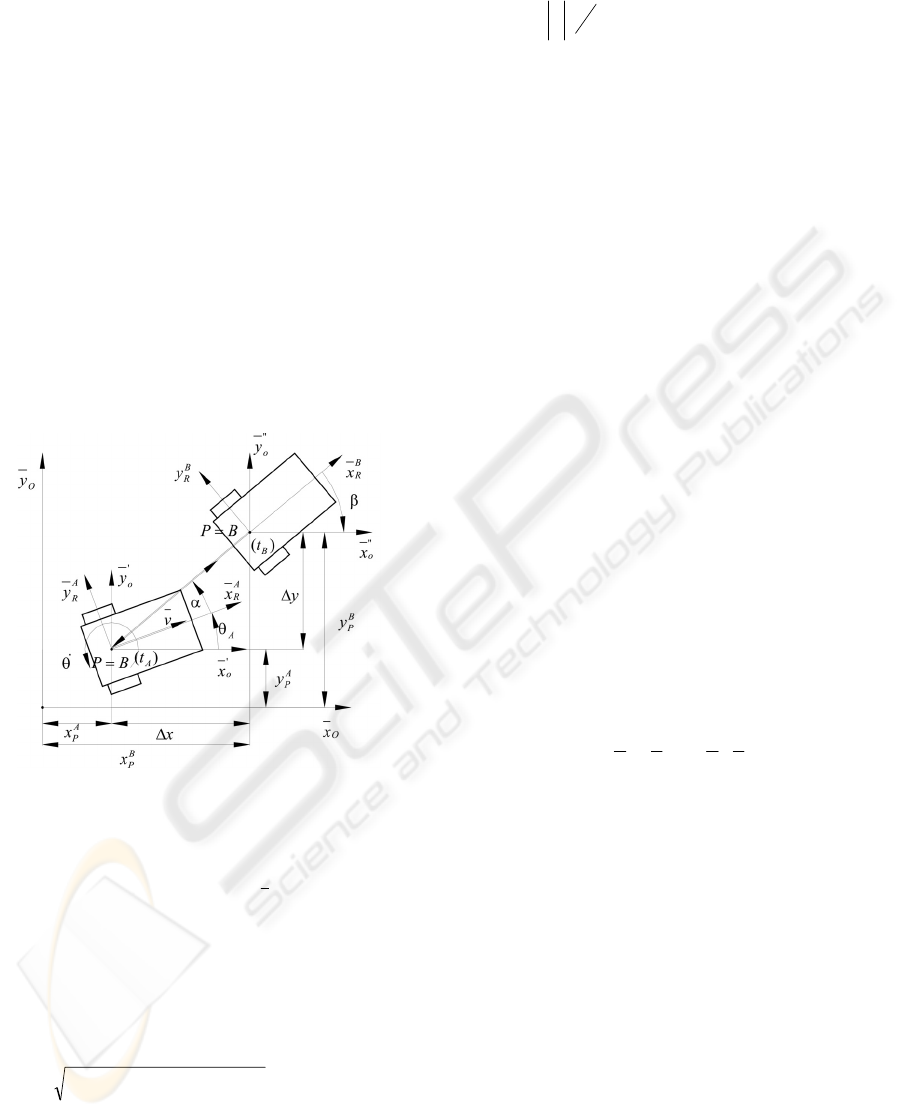
point to point movement. It is descried in Figure 1.
Figure 1: The point
)(
A
tB
to point
)(
B
tB
movement.
During point to point movement, translation
(
yx ΔΔ ,
) and rotation (
α
and /or
β
) is obtained. In
addition, translation velocity
v
and rotational
velocity
•
θ
are also obtained.
The rotation estimation is induced from the ego
robot’s rotational velocity and complex motion
control equation during two consecutive image
frames. The rotational angle follows:
)*4/()180*|(|
tr
EEt ×Δ×±=Δ
•
θθ
⎪
⎩
⎪
⎨
⎧
<−
≥+
•
•
0:
0:
θ
θ
(2)
where
tΔ
is the elapsed time between two
consecutive frames,
r
E
and
t
E
is rotation and
translation error. These
r
E
and
t
E
are determined
experimentally.
n
n
i
i
⎟
⎠
⎞
⎜
⎝
⎛
=
∑
=
••
1
||
θθ
. where n is the number of rotation
velocities during
t
Δ
.
The
x
Δ
and
y
Δ
are induced from forward
kinematics.
)sin(2/)(
θ
Δ×Δ×+−=Δ tvvx
lr
)cos(2/)(
θ
Δ×
Δ
×
+
=
Δ
tvvy
lr
(3)
The x
0
and y
0
of Figure. 1 are equivalent to
X
direction of camera coordinates and
Z
direction
of camera coordinates respectively.
From equation (2) and (3), the physical
movement of ego robot is determined in terms of
translation and rotation. These translation value and
rotation angle are used to filter out features of VO.
Namely the features which have bigger rotational
angles and translation values than the equation (2)
and (3) will be excluded for VO. The excluded
features represent fast moving objects comparing to
movement of ego robot. The remaining features after
excluding fast moving features are used for
computing mean (
T
μ
,
R
μ
) and Absolute Standard
Deviation (ASD:
T
σ
,
R
σ
) in terms of translation and
rotation. As a result of computing ASD, two ASDs
(+/- ASD:
T
σ
±
,
R
σ
±
) are obtained. The features
that have bigger translation values than
TT
σ
μ
−
and
bigger rotational angle than
RR
σ
μ
−
will be kept as
inliers for VO. Therefore finally we can compute a
pair of mean inliers, one corresponding to the
previous frame and the other to the current frame:
(
)
11
,
−− tt
ZX
,
()
tt
ZX ,
They are used for computing translation and
rotation of robot as part of VO.
2.3 Hybrid Filter for Localization
The localization in this paper is relative global. The
robot’s position is accumulated from starting
position along with robot’s path. This relative global
position is obtained by hybrid filter. The hybrid filter
consists of Visual Odometry (VO)-based motion
estimation and ego motion model based motion
estimation. The hybrid filter switches VO estimation
to ego motion estimation according to current
situation. The VO is mainly used for robot’s
localization. The ego motion estimation is used
when visual information is lost and no tracking
features exist in the scene. The case of loss of visual
information especially appears in clumsy and
compact indoor environment when the scene is too
VISAPP 2010 - International Conference on Computer Vision Theory and Applications
318
close. The case of no available tracking features
appears in the poor illuminated or in the no textured
image scenes.
The proposed hybrid-filter-based localization can
be used in both indoor and outdoor environment.
The equation of the relative global localization
follows:
We choose the X, Z coordinates of the 3D feature
points from the previous and current
frames,
()
11
,
−− tt
ZX
,
()
tt
ZX ,
. The position estimation
of robot in terms of X, Z is:
() ()
θθ
Δ−•=Δ−•= cos,sin
currcurr
ZX
curraccumaccumcurraccumaccum
ZZZXXX +=+= ,
(4)
where
()()
2
1
2
1 tttt
ZZXX −+−=•
−−
()
πθ
/180*)/()(arccos BABA ⋅=Δ
,
[]
π
π
θ
,−=Δ
is yaw angle.
tttt
ZZXXBA
11 −−
+=⋅
,
()()
2
1
2
1 −−
+=
tt
ZXA
,
() ()
22
tt
ZXB +=
.
curr
X
is X axis mapping of
•
,
curr
Z
is Z axis
mapping of
•
.
3 PROPOSED MAP BUILDING
The 3D map is registered along with robot’s path.
Tyzx’s stereo camera is used for proposed 3D map
building. The proposed map-building method
generates complete road surface as well as 3D
environment. Two map building algorithms are
introduced to solve the above mentioned problems.
The 3D road pixel determination is based on X-Y
projection. The 3D environment is built through
temporal fusion using a dense accumulation–based
temporal filter.
For the 3D road pixel determination, the row
position with the maximum pixel number in the
filtered X-Y projection map is determined by
searching. Lets call it
indexroad
r
_
.
The 3D points which are in the
indexroad
r
_
row
cells of scoring map are assumed as the 3D points of
the road surface. From experiments the 3D points of
road surface are between
1
_
−
indexroad
r
and
1
_
+
indexroad
r
. This approach was proved to be
very simple and very robust in the structured
environment.
For the 3D environment building, the
successive depth images are fused using a temporal
filter. The temporal filter is implemented by
exploiting two information: position height and its
time stamp. At each step we replace the current
position height if a new height is provided for that
position, or discard the height having a time step
older than the current one with a pre-defined
threshold.
The pixels of road surface which are extracted in
the first case, but also the pixels corresponding to
the other elements of the environment are
accumulated by the temporal filter. Consequently the
accumulated 3D environment surface is generated.
This 3D relative environment surface is registered
by 2D translation and rotation on the 3D world
coordinates.
The obtained local 3D road surface is registered
based on the following equation.
⎥
⎥
⎥
⎦
⎤
⎢
⎢
⎢
⎣
⎡
+
⎥
⎥
⎥
⎦
⎤
⎢
⎢
⎢
⎣
⎡
⎥
⎥
⎥
⎦
⎤
⎢
⎢
⎢
⎣
⎡
−
=
⎥
⎥
⎥
⎦
⎤
⎢
⎢
⎢
⎣
⎡
t
t
t
env
i
env
i
env
i
rr
rr
i
t
i
t
i
t
Z
Y
X
Z
Y
X
Z
Y
X
θθ
θθ
cos0sin
010
sin0cos
(5)
where (
t
X
,
t
Y
,
t
Z
) is the global position of the robot
at time
t
, and
r
θ
is relative yaw at time
t
,
(
env
i
X
,
env
i
Y
,
env
i
Z
) is the relative environment pixel
position at time
t
(
i
goes from 0 to the total number
of 3D pixels) and (
t
i
X
,
i
t
Y
,
t
i
Z
) is the new position
of the pixel relative to the global coordinate system.
The global position (
t
X
,
t
Z
) and relative yaw (
r
θ
)
comes from
{
}
θ
Δ
,,
accumaccum
YX
of equation (4).
The proposed Hybrid-filter-based localization and
map building can be run in real-time conditions and
variant environments (indoor and outdoor).
4 EXPERIMENTS
As mentioned in Section 2.2, the ego robot is
modeled as differential drive robot, and empirical
parameters determination for translation error and
rotational angle error is required. These errors
mainly come from robot’s weight load. In order to
determine translation error and rotational error, robot
navigates pre-defined path with constant
commanded velocity (100 mm/sec). The pre-defined
path is a rectangle (1500 mm x 1500 mm).
As varying empirical parameters (
E
r
and E
t
), the
actual robot trajectory is varying too. The
parameters are determined when the robot trajectory
has the smallest error against pre-defined path. The
behavior of the robot navigation looks like car due to
RELIABLE LOCALIZATION AND MAP BUILDING BASED ON VISUAL ODOMETRY AND EGO MOTION
MODEL IN DYNAMIC ENVIRONMENT
319

differential drive modeling. The results
corresponding to different sets of translation and
rotation error parameters are presented in Figure 2.
-1000 -500 0 500
1000
1500 2000 2500
-500
0
500
1000
1500
2000
2500
-1000 -500 0 500
1000
1500 2000 2500
-500
0
500
1000
1500
2000
2500
(a) In case of
r
E
= 0.08 and
t
E
=940
-1000 -500 0 500
1000
1500 2000 2500
-200
0
200
1000
1200
1400
1800
400
600
800
1600
-1000 -500 0 500
1000
1500 2000 2500
-200
0
200
1000
1200
1400
1800
400
600
800
1600
(b) In case of
r
E
= 0.08 and
t
E
=1010
Figure 2: Ego motion calibration (blue: encoder data, red:
estimated trajectories according to translation and rotation
velocity)
Figure 3: 3D data acquisition in variant environments.
The parameter of rotation error is fixed to 0.08,
and only the parameter of translation error changes
from 940 to 1020. The blue line (rectangle)
represents raw encoder data that is obtained in each
four corners of pre-defined rectangle path.
The red line represents robot’s trajectory that is
computed by translation value and rotation angle
along with time stamps. The minimum mismatched
value (10 cm between departure position and
returned position) is obtained when the parameter of
translation error is about 1000. This case can be seen
in Figure 2(b). These obtained error parameters are
used in Equation (2) in order to provide maximum
accuracy of VO.
The road surface extraction by X-Y projection
and temporal filter is presented in Figure 3. The
extracted road surface pixels by X-Y projection is
presented in blue color on the original image (e.g.
(a)). Their corresponding 3D positions are displayed
in (b), (c), and (d). The green spheres in the (b), (c),
and (d) represents the 3D points before temporal
filtering. The gray points represent the 3D points
added by fusing 10.000 images using temporal
filtering.
The fusion of successive images has as
consequence the increase of the density of the 3D
representation together with the increase of the
representation accuracy.
To evaluate accuracy of localization, robot
passes though 3 known points (2 meters, 6 meters,
and 10 meter) in 5 turns. It is presented in Table 1.
We obtained 1.5875 percentages of average error.
As final experiment, the robot navigates in long
indoor environment. When the robot navigates
indoor, the robot met many different environment
variations (non-uniform illuminations Figure 4. (1-
3), narrow paths Figure 4. (3-6), and non textured
road surface Figure 4. (6-7)). In spite of these facts
3D road surface and 3D environment is well
registered along with the robot path.
5 CONCLUSIONS
This paper proposed a new robust localization and
map building method based on VO and ego motion
model. Robot navigates in dynamic environment hat
contains moving objects, non-uniform illumination,
and non textured road surfaces. The achieved
accuracy of position estimation is 1.5875 errors
percentage in 10 meters.
(a) Indoor (b) 3D data (front-view)
Fusion with Temporal filter: 3475509 points (gray and green);
No fusion: 7192 points (green)
(c) 3D data (side-view) after 1000 frames accumulation
Fusion with Temporal filter: 99571 points (gray and green);
No fusion: 353 points (green)
(d) 3D Road data (side-view) after 1000 frames accumulation
VISAPP 2010 - International Conference on Computer Vision Theory and Applications
320
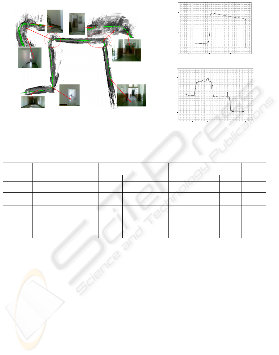
(1)
(2)
(3)
(4)
(5)
(6)
(7)
(a) Raw accumulated image and reconstructed 3D road surface and 3D
environment.
Z (mm)
0 10000 20000 30000 40000 50000 60000
X (mm)
-40000
-30000
-20000
-10000
0
10000
b) Distance variation along with navigation path.
Sampled Data
0 50 100 150 200 250 300 350 400 450
Angle (degree)
-150
-100
-50
0
50
100
150
(c) Angle variation along with navigation path.
Figure 4: Result Localization and map building in the long distance navigation (about 110 meter).
Table 1: Accuracy comparison at each known position.
Measuring
Nr.
2 meters
(mm)
6 meters
(mm)
10 meters
(mm)
Remark
Error
(%)
X Z Yaw X Z Yaw X Z Yaw
1 35.65 1847.5 -1.82 259.46 5625.01 -3.78 789.82 9703.77 -10.57 2.617
2 80.29 2066.14 -4.23 416.25 5981.49 -5.46 900.35 10118.09 -6.98 0.766
3 39.9 2062.2 -2.52 329.59 6095.2 -9.2 1298.73 10270.26 -14.44 1.729
4 95.14 1901.13 -4.98 541.43 5704.66 -6.18 1442.69 9646.03 -15.59 2.042
5 62.85 1975.55 -2.97 305.59 6018.14 -3.99 1063.45 10130.03 -16.25 0.783
REFERENCES
D. Nistér, O. Naroditsky and J. Bergen, 2004 “Visual
odometry”,
Proc.IEEE Computer Society Conference
on Computer Vision and Pattern Recognition (CVPR
2004)
, Vol. 1, pp. 652-659.
A. Howard, 2008, “Real-Time Stereo Visual Odometry for
Autonomous Ground Vehicles”,
International
Conference on Robots and Systems (IROS)
, Sep..
M. Agrawal and K. Konolige, 2007, “Rough terrain visual
odometry”,
In Proc. International Conference on
Advanced Robotics (ICAR)
, Aug..
K. Konolige, M. Agrawal, R.C. Bolles, C. Cowan, M.
Fischler, and BP Gerkey, 2008 “Outdoor mapping and
navigation using stereo vision”,
Intl. Symp. On
experimental Robotics
, pp. 179-190.
J. Shi and C. Tomasi, 1994, “Good Features to Track”,
IEEE conference on Computer Vision and Pattern
Recognition
(CVPR94), pp. 593-600.
B. D. Lucas and T. Kanade, 1981, “An iterative image
registration technique with an application to stereo
vision”,
Proceedings of the 1981 DARPA Image
Understanding Workshop
(pp.121-130).
Y. Guo, V. Gerasimov, G. Poulton, 2006, “Vision-Based
Drivable Surface Detection in Autonomous Ground
Vehicles,” IEEE/RSJ International Conference on
Intelligent Robots and Systems
, pp. 3273–3278.
B. Sofman, E. Lin, J. Bagnell, N. Vandapel, and A. Stentz,
2006, “Improving robot navigation through self-
supervised online learning,” In Robotics: Science and
System (RSS)
, Cambridge.
H. Dahlkamp, A Kaejler, D. Stavens, S. Thrun, G.R.
Bradski, 2006, “Self-supervised Monocular Road
Detection in Desert Terrain,”
Robotics:Science and
Systems II
.
http://www.tyzx.com
RELIABLE LOCALIZATION AND MAP BUILDING BASED ON VISUAL ODOMETRY AND EGO MOTION
MODEL IN DYNAMIC ENVIRONMENT
321
