TESSELLATING OCEAN SURFACES
Anna Puig-Centelles, Francisco Ramos, Miguel Chover
Universitat Jaume I, Castellon, Spain
Oscar Ripolles
Universitat Politecnica de Valencia, Valencia, Spain
Mateu Sbert
Universitat de Girona, Girona, Spain
Keywords:
Ocean simulation, Tessellation, GPU, Geometry Shader.
Abstract:
Modeling and rendering realistic ocean scenes has been thoroughly investigated for many years. Its appearance
has been studied and it is possible to find very detailed simulations with a high degree of realism. Nevertheless,
real-time management of the huge heightmaps that are necessary for rendering ocean is still not solved. We
propose a new technique for tessellating the ocean surface on GPU. This technique is capable of offering
view-dependent approximations of the mesh while maintaining coherence among the extracted approximations
when refining or coarsening the mesh. This feature is very important as most solutions previously presented
must re-tessellate from the initial mesh.
1 INTRODUCTION
Simulating ocean surfaces is a very complicated chal-
lenge, as ocean is composed of different elements that
form a very complex system. Most authors simulate
an ocean as an unbounded water surface that is rep-
resented as a heightmap. In these simulations, the
height of each vertex is modified in real time to of-
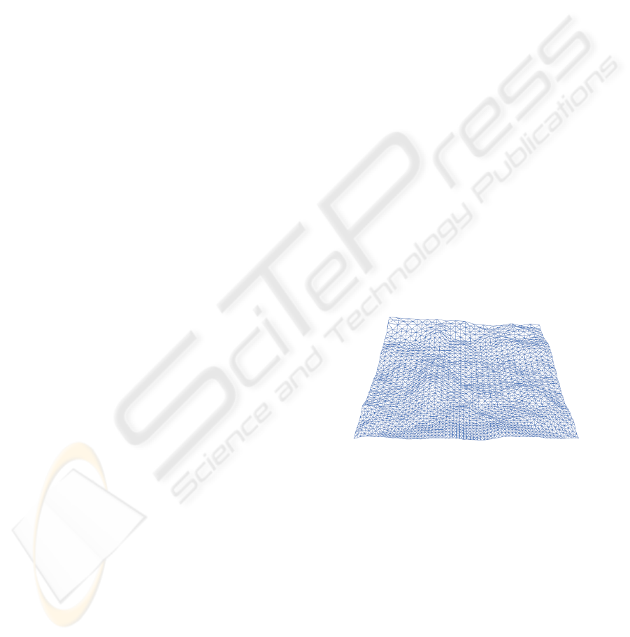
fer the sensation of wave movement. Figure 1 de-
picts a snapshot of a mesh simulating ocean move-
ment in a given instant of the animation. Other com-
plex phenomena, such as foam, spray or splashes are
usually modeled and rendered using particle systems
(Peachey, 1986; Darles et al., 2007).
Managing the mesh representing the ocean still
poses a limitation in simulating ocean. A technique
that several authors propose is the tessellation of the
surface. Moreover, it is possible to find adaptive solu-
tions where some areas of the mesh are more detailed
than the others, depending on the criteria used by the
application. It is possible to find in the literature many
solutions aimed at tessellating by exploiting GPU fea-
tures, although not many have been applied to ocean
surfaces.
This paper introduces a new adaptive tessellation
Figure 1: An ocean can be seen as an animated heightmap.
scheme which works completely on GPU. Figure 1
presents an example of our algorithm where those ar-
eas closer to the camera are more refined. In addi-
tion, our proposed algorithm is capable of maintain-
ing coherence among the extracted approximations as
it can re-use the latest calculated approximation when
increasing or decreasing the detail. Lastly, the simula-
tion that we propose simulates wave movements with
Perlin noise (Perlin, 1985) calculated on GPU.
This paper has the following structure. Section 2
presents the state of the art on ocean simulation and
tessellation. Section 3 thoroughly describes the tes-
sellation technique that we present. Section 4 offers
some results on the presented technique. Lastly, Sec-
319
Puig-Centelles A., Ramos F., Chover M., Ripolles O. and Sbert M. (2010).
TESSELLATING OCEAN SURFACES.
In Proceedings of the International Conference on Computer Graphics Theory and Applications, pages 319-322
DOI: 10.5220/0002827003190322
Copyright
c
SciTePress
tion 5 includes some conclusions on the developed
techniques and outlines our future work.
2 RELATED WORK
In this state of the art we will describe GPU tessel-
lation techniques that have been developed for ren-
dering ocean scenes. There have been several re-
cent attempts to generate in real-time adaptive wa-
ter surfaces on graphics hardware. Hinsinger et al.
(Hinsinger et al., 2002) rely on an adaptive sampling
of the ocean surface and the wave animation, dictated
by the camera position. The tessellation and wave-
form superposition is performed on the CPU and up-
loaded to the GPU each frame, which is the bottleneck
of their approach. Johanson (Johanson, 2004) pre-
sented the projected grid concept, which creates a grid
whose vertices are even-spaced in post-perspective
camera space. This representation provides spatial
scalability and the possibility of developing a fully-
GPU implementation is described. In paper (Yang
et al., 2005), the authors offer GPU-based tessella-
tion by using a previous adaptive scheme for ter-
rain rendering. Their tessellation scheme uses a re-
stricted quad-tree where two neighbouring areas with
different resolutions can only vary to a limited ex-
tent. Lastly, in (Demers, 2005) Demers et al. pre-
sented a simulation which is adaptively tessellated in
eye space, mapping a regular grid to the intersection
of the ocean plane and the camera viewport.
3 OUR GPU-BASED
TESSELLATION SCHEME
Many of the tessellation algorithms presented before
modify the detail of the triangles following some cri-
terion applied to the triangle. The calculations in-
volved could consider the distance of the triangle to
the camera or its position in the screen. Neverthe-
less, applying the level-of-detail criterion in a trian-
gle basis implies a limitation for adaptive solutions,
like the appearance of noticeable cracks and holes in
the mesh. These cracks are due to the introduction of
T-vertices, which appear commonly in tessellation al-
gorithms when a vertex is positioned on the edge of
another triangle.
In order to avoid crack problems, some authors
have proposed to apply the refinement criterion only
to the edges of the triangle. Therefore, if an edge
needed refinement, then both triangles sharing the
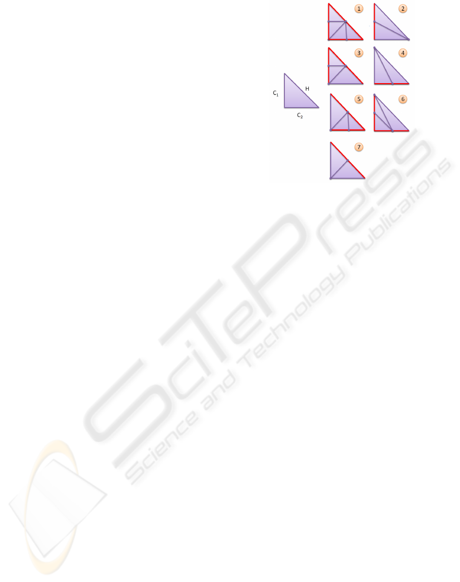
edge would act accordingly. Schmiade et al. de-
Figure 2: Tessellation patterns (Schmiade, 2008).
scribed some edge-based patterns for tessellating tri-
angles which completely avoided the appearance of
T-vertices (Schmiade, 2008). Figure 2 presents, on
the left side, an initial rectangular triangle where its
hypotenuse and catheti (or legs) are depicted anti-
clockwise as H, C
1
and C
2
. Next, the seven tessel-
lation patterns introduced by Schmiade et al. are pre-
sented (labeled from 1 to 7), where the edges of the
original triangle that need refinement are depicted in
red. Each pattern shows the tessellation that would be
necessary depending on the combination of edges that
need refinement.
In our proposal we will use these patterns, as
they can assure that no T-vertices are introduced and
that the continuity of the mesh is maintained. It
is worth mentioning that we will not store precom-
puted patterns on GPU memory as other solutions do
(Boubekeur and Schlick, 2005). We just code in the
Geometry Shader the seven cases that we follow so
that the coordinates of the new vertices can be eas-
ily calculated from the coordinates of the two vertices
that define the edge.
3.1 Our Proposed Algorithm
The main feature of the framework that we are pre-
senting is the possibility of refining or coarsening the
mesh while maintaining coherence. By coherence we
refer to the re-use of information between changes in
the level-of-detail. In such way, the latest extracted
approximation is used in the next step, optimizing the
tessellation process and improving the performance.
When refining the mesh, the algorithm checks
each edge to see whether they need refinement. De-
pending on the combination of edges that need more
detail, the algorithm selects a pattern (see Figure 2).
GRAPP 2010 - International Conference on Computer Graphics Theory and Applications
320

Each of these generated triangles stores the spatial co-
ordinates, the texture information and any other infor-
mation needed for rendering. In addition, it is nec-
essary to output for each new triangle two pieces of
information:
• A number indicating the tessellation depth for the
triangle.
• A number coding the tessellation patterns that
have been applied, keeping this information in
patternIn f o.
The need of storing these two values is due to the
fact that we must know how a particular triangle was
created in order to know how we should modify it
when swapping to a lower level of detail. On the one
hand, the depth value will simply indicate how many
tessellation steps have affected a particular triangle.
On the other, the patternIn f o number is used to store
all the patterns that have been applied to refine a trian-
gle. This value is obtained following Equation 1. In
this equation appliedPattern refers to the type of the
latest pattern, the one that we have used to create this
triangle. The value numberO f Patterns refers to the
number of available patterns that we can apply in our
tessellation algorithm. In our case we will use the 7
patterns presented in Figure 2 and, as a consequence,
numberO f Patterns will be equal to 7.
patternIn f o = patternIn f o + appliedPattern · numberO f Patterns
depth
(1)
This patternIn f o value will not be the same for all
the triangles belonging to the same parent. When tes-
sellating a triangle, for example with the pattern used
when the hypotenuse and both legs are refined (see
pattern 1 in Figure 2), four triangles are output. Nev-
ertheless, only one of these triangles will be needed
when diminishing the detail. Three of them will be
discarded and the other one will be modified to recre-
ate the geometry of the parent triangle. Therefore, the
patternIn f o value will be calculated with Equation 1
for the triangle that survives and will be 0 for the ones
that will be eliminated. We will see the coarsening
process in more detail in the following subsection.
3.1.1 Coarsening the Mesh
A different process should be applied when dimin-
ishing the detail of the mesh. The depth and
patternIn f o values presented above are the elements
that enable our algorithm to recover less detailed ap-
proximations without having to start again from the
coarsest approximation. It is important to underline
that this is one of the main features of the method we
are proposing.
The first step would be to find out whether the pro-
cessing triangle can be discarded or if it is the triangle
in charge of retrieving the geometry of the parent tri-
angle. A positive patternIn f o value indicates that it
is the latter case, the triangle will calculate the spatial
coordinates of its parent triangle.
In order to retrieve the spatial coordinates of the
parent triangle we must know which pattern was ap-
plied to create the existing triangle. This is due to the
fact that for each pattern we will perform different cal-
culations for retrieving the three vertices of the parent
triangle. In this situation the patternIn f o value helps
us to know which pattern was applied, as the latest
pattern can be obtained with the next equation:
latestPattern =
patternIn f o
numberO f Patterns
depth−1
(2)
Once we know which pattern was applied, we cal-
culate the position of the vertices and we output the
new geometry with the new patternIn f o value ob-
tained with Equation 3. The way we calculated this
value assures that we will be able to continue coars-
ening the mesh or refining it without any problem.
patternIn f o = patternIn f o − latestPattern · numberO f Patterns
depth−1
(3)
3.2 Camera Movement
We have described how the tessellation process works
but we have considered that the location of the plane
splitting the area where the mesh is and is not tessel-
lated remains unaltered. Nevertheless, in a real case
this line keeps moving all the time as it is usually re-
lated to the camera position.
In these cases, a slightly different process is ap-
plied to correct the appropriate triangles. This algo-
rithm checks each triangle to see whether, with the
new criterion, their parent triangle would need a dif-
ferent tessellation. In that case, the algorithm will
coarsen the triangles and refine them again. It is
important to underline that both processes (coarsen-
ing and refining again) are executed at the same time
and can be continuously executed while the camera is
moving. In this particular case the depth value is very
important as it enable us to know how many tessella-
tion coarsements and refinements must be executed in
those areas that are affected by the camera movement.
4 RESULTS
In this section we will study the performance of our
tessellation method. Our scheme was programmed
with GLSL and C++ on a Windows Vista Operating
TESSELLATING OCEAN SURFACES
321
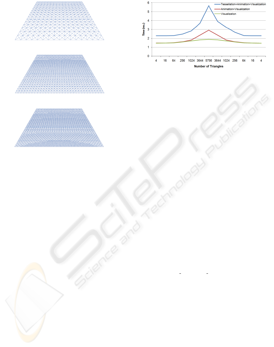
(a) Second tessellation step (1,024 triangles).
(b) Third tessellation step (3,644 triangles).
(c) Fourth tessellation step (5,756 triangles).
Figure 3: Sample tessellation using a distance criterion.
System. The tests were carried out on a Pentium D
2.8 GHz. with 2 GB. RAM and an nVidia GeForce
8800 GT graphics card.
First, we offer some visual results of the tessella-
tion algorithm. Figure 3 presents some snapshots of
a tessellation case where an initial mesh composed of
four triangles is refined according to the distance to
the camera. In the more refined meshes it is possible
to see how the tessellation is not uniform, as those ar-
eas of the mesh which are closer to the observer are
more tessellated than those that are farther. These fig-
ures show how the tessellation process increases the
detail of an input mesh without introducing cracks or
other artifacts. Figure 1 shown at the beginning of this
article presented the most detailed tessellation (Figure
3(c)) with Perlin noise applied to simulate waves.
In order to test the performance of our technique,
Figure 4 presents the time needed for tessellating, an-
imating and rendering the example depicted in Figure
3. This Figure shows how the noise calculations in-
volve increasing the rendering time in 10% while the
tessellation supposes an increase of 60%.
5 CONCLUSIONS
We have presented a method for simulating ocean in
real-time. The presented approach is based on the use
of a new adaptive tessellation scheme which exploits
Figure 4: Performance obtained using a distance criterion.
coherence among extracted approximations. Accord-
ingly, by storing some information, we are capable of
reusing the latest extracted mesh when refining and
coarsening the surface. For future work we are fo-
cused on the inclusion of more effects like refraction
or the interaction of objects with the surface.
ACKNOWLEDGEMENTS
This work has been supported by the Spanish Min-
istry of Science and Technology (TIN2007-68066-
C04-02, TIN2007-68066-C04-01) by Bancaja (P1
1B2007-56) and by ITEA2 (IP08009).
REFERENCES
Boubekeur, T. and Schlick, C. (2005). Generic mesh re-
finement on GPU. In Proc. of the EUROGRAPHICS
conference on Graphics hardware, pages 99–104.
Darles, E., Crespin, B., and Ghazanfarpour, D. (2007). Ac-
celerating and enhancing rendering of realistic ocean
scenes. In Proc. of WSCG 2007, pages 287–294.
Demers, J. (2005). The making of clear sailing, secrets of
the NVIDIA demo team. http://www.nzone.com/
object/nzone clearsailing makingof1.html.
Hinsinger, D., Neyret, F., and Cani, M. (2002). Interactive
animation of ocean waves. In Eurographics sympo-
sium on Computer animation, pages 161–166.
Johanson, C. (2004). Real time water rendering-introducing
the projected grid concept. Technical report, Master of
Science Thesis, Lund University.
Peachey, D. R. (1986). Modeling wave and surf. Computer.
Graphics, 20(4):75–83.
Perlin, K. (1985). An image synthesizer. SIGGRAPH Com-
put. Graph., 19(3):287–296.
Schmiade, T. (2008). Adaptive GPU-based terrain render-
ing. Master’s thesis, University of Siegen.
Yang, X., Pi, X., Zeng, L., and Li, S. (2005). Gpu-based
real-time simulation and rendering of unbounded
ocean surface. In Int. Conf. on Computer Aided De-
sign and Computer Graphics, pages 428–433.
GRAPP 2010 - International Conference on Computer Graphics Theory and Applications
322
