
ADAPTIVE PATCH-BASED INPAINTING FOR IMAGE BLOCK
RECOVERY
Yunqiang Liu
Barcelona Media - Innovation Center, University of Pompeu Fabra, Barcelona, Spain
Jin Wang, Huanhuan Zhang
Philips Research Asia - Shanghai, China
Keywords:
Image block recovery, Inpainting, Error propagation, Combination strategy.
Abstract:
This paper presents an adaptive patch-based inpainting algorithm for image block recovery in block-based
coding image transmission. The proposed approach is based on prior information - patch similarity within
the image. By taking advantage of the information, we recover the lost pixels by copying pixel values from
the source based on a similarity criterion to keep local continuity. The pixel recovery is performed in a
sequential fashion in which the recovered pixels can be used in the recovery process afterwards. In order
to alleviate the error propagation with sequential recovery, we proposed an adaptive combination strategy
which merges different directional recovered pixels according to the confidence of the estimated recovery
performance. Experimental results show that the proposed method provides significant gains in both subjective
and objective measurements.
1 INTRODUCTION
With the advent of multimedia communication, im-
age/video transmission is becoming more and more
important. Unfortunately, transmission error is in-
evitable on most channels such as wireless channels
and the Internet which are not reliable enough to
guarantee error-free transmission. Meanwhile, exist-
ing multimedia compression standards such as JPEG,
MPEG-2 and H.264 (Sullivan and Wiegand, 2005)
use the variable length coding (VLC) with block-
based structure. The bit stream encoded by those stan-
dards is very sensitive to transmission errors (Kung
et al., 2006). Even one single bit error may cause the
loss of a whole block. And in video transmission, the
mistakes in current blocks even propagate to the fol-
lowing blocks or the following frames, which will re-
sult in serious degradation in the visual quality of the
decoded image.
Error recovery as a post-processing module is
widely adopted to alleviate the negative effect of the
erroneous blocks (Wang and Zhu, 1998) which at-
tempts to reconstruct corrupted pixels utilizing the
available neighbor information, without modifying
source and channel coding schemes. Comparing to
other existing error resilient approaches (Wang et al.,
2000) as the Forward Error Correction and the inter-
active methods, no extra delay or redundant informa-
tion will be added to the bit stream.
In general, according to correlation information,
error recovery methods could be divided into two
classifications (Agrafiotis et al., 2006): spatial error
recovery (SER) and temporal error recovery (TER).
The former utilizes spatial neighbor information to fill
the missing area whereas the latter utilizes temporal
information from successive frames. The spatial er-
ror recovery is often adopted in image sequence, intra
coded frame and areas of low temporal redundancy in
inter-coded frame.
A number of spatial recovery approaches have
been proposed already in the literature. Bilinear inter-
polation (Wang et al., 2002) is a simple and efficient
method which utilizes the nearest correctly decoded
pixels to reconstruct the lost areas with weighted av-
erages of these pixels. Rane et al. (Rane et al., 2002)
estimate the lost information in the frequency domain
based on the spatial smoothing constraint on the re-
constructed blocks. While the obtained results are
fairly good, these algorithms provide smooth recon-
structions in image regions. Several methods try to
52
Liu Y., Wang J. and Zhang H. (2010).
ADAPTIVE PATCH-BASED INPAINTING FOR IMAGE BLOCK RECOVERY.
In Proceedings of the International Conference on Computer Vision Theory and Applications, pages 52-59
DOI: 10.5220/0002832000520059
Copyright
c
SciTePress

mitigate this problem by interpolating missing pixels
along estimated edge directions such as directional in-
terpolation (Kim et al., 2006) and verge points based
method (Gao et al., 2007). In (Hong et al., 1999),
error recovery is performed recursively for bands of
missing pixels, using border pixels of surrounding
blocks and already concealed pixels of the recovered
block. The concept of sequential error recovery is also
followed in the orientation adaptive sequential inter-
polation (OASI) approach (Li and Orchard, 2002).
Some methods address the problem of recovering
missing data from different point of view. The best
neighborhood matching (BNM) method (Wang et al.,
1998) exploits block wise similarities within an image
to replace whole missing blocks through a search pro-
cess in the vicinity. Texture inpainting method, trig-
gered in part by texture synthesis (Efros and Leung,
1999), has shown promising results on restoring cor-
rupted image data, which is based on the similarity
between their local neighborhood and the surround-
ing neighborhoods. Criminisi et al. (Criminisi and
Perez, 2003) present an order-based image inpainting
method that extends the texture synthesis approach by
imposing higher priorities in the restoration order for
pixels lying in the neighborhood of edges, thereby
preserving better edge sharpness and continuity. In
(Arias et al., 2009) the authors propose a non-local
variational model to address the texture-oriented in-
painting problem and provide impressive results. In
(Bertalmio et al., 2003) Bertalmio et al. decompose
the image into two functions, one for the texture in-
gredient and the other for the geometry structure of
the image. Then they fill in the texture component
using texture synthesis, and fill in the structure part
using a classical inpainting approach based on partial
differential equation models (Bertalmio et al., 2000)
(Chan and Shen, 2001).
This paper presents an adaptive patch-based in-
painting algorithm for image block recovery in block-
based coding image transmission. The proposed ap-
proach is based on prior information - patch similarity
within the image. By taking advantage of this infor-
mation, we recover the lost pixels by copying pixel
values from the source based on a similarity criterion
to keep local continuity. The pixel recovery is per-
formed in a sequential fashion in which the recovered
pixels, as well as the uncorrupted pixels in the neigh-
bor area, can be used in the recovery process after-
wards. In order to alleviate the error propagation with
sequential recovery, we proposed an adaptive com-
bination strategy to reconstruct the lost block, which
merges different directional recovered pixels accord-
ing to their confidence. The confidence is estimated
by the dissimilarity and the amount of reliable infor-
mation in the patch.
The remainder of this paper is structured as fol-
lows. In Section 2, we give an overview of the
proposed adaptive patch-based inpainting algorithm.
Section 3 presents the proposed method in detail. Sec-
tion 4 gives the results and comparisons, and conclu-
sions are drawn in Section 5.
2 ALGORITHM OVERVIEW
Before the application of our image recovery ap-
proach, it is assumed that that we can locate the error
region in the decoded video or image with some
error detection algorithms. Most of traditional error
recovery methods, such as bilinear interpolation,
directional interpolation and OASI, perform as a low
pass filter or directionally low pass filter in nature.
They cannot recover accurately the sharp edge and
texture within the lost region, however, the edge and
texture information is very important for the human
vision system. It is introduced by the following two
reasons (Wang et al., 1998). First, the information
source to estimate pixels in the missing blocks is the
neighboring pixels in a very limited local region.
Second, these methods rely on some predefined
constraints on the lost blocks such as the recovered
blocks should be smoothly connected with adjacent
regions either in spatial or in transform domain.
(a) (b)
(c) (d)
Figure 1: Textural and edge images.
ADAPTIVE PATCH-BASED INPAINTING FOR IMAGE BLOCK RECOVERY
53
In order to overcome the above problems, the BNM
method exploits block wise similarities within an im-
age to replace whole missing blocks through a search
process in not only neighboring regions, but also re-
mote regions within the image. The method can re-
construct the simple texture block (Figure 1(a)) and
single strong edge (Figure 1(b)) effectively, and it can
keep the sharp edge and details of texture in the lost
block. However, BNM fails to recover the region with
multiple edges (Figure 1(c)) or complex texture (Fig-
ure 1(d)), because there are much less matching pos-
sibilities for the lost blocks in the image. The BNM
method takes the missing block as a whole to find a
similar area in the vicinity. When the missing block
is large, such as 8x8 or 16x16 which is very common
in block-based image-coding systems, it is very diffi-
cult to find the similar area especially for the situation
in Figures 1(c) and 1(d). Based on this observation,
we adopt the approach of patch-based inpainting to
reconstruct the missing regions. The approach grows
the missing area pixel by pixel, based on prior infor-
mation - patch-wise self-similarity within the image.
By taking advantage of the information, we recover
the lost pixels by copying pixel values from the source
based on a similarity criterion to keep local continu-
ity. The pixel recovery is performed in a sequential
fashion in which the recovered pixels, as well as the
uncorrupted pixels in the neighbor area, can be used
in the recovery process afterwards (Li and Orchard,
2002). This sequential fashion introduces a bias on
the later recovered pixels. Because the later recovered
pixels depend on the previous recovered pixels, error
propagation is inevitable. The quality of the recovered
image is highly influenced by the order in which the
filling process proceeds. The pattern of error prop-
agation varies with the recovery order. In order to
alleviate the error propagation with sequential recov-
ery, we perform the patch-based inpainting algorithm
from different directions. Then we calculate the con-
fidence of the interpolated pixels from different direc-
tions, and finally combine them by adaptive weighting
according to the confidence.
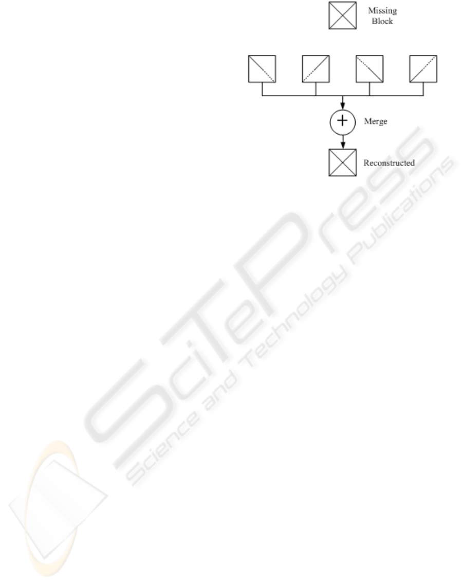
The proposed adaptive combination strategy is in-
spired by the work in (Li and Orchard, 2002). The
authors adopt a linear merge strategy, in which the
weights only depend on the distances of the given
pixel to the four borders of the block. These distances
cannot fully reflect the contribution of the pixels from
different directions to the interpolated pixel. In our
method, we introduced two confidence measurements
to evaluate the contribution: reliability confidence
and similarity confidence. The former measures the
amount of the reliability of the available pixels for
recovering the missing one. The latter evaluates the
Figure 2: Reconstruction of lost blocks.
quality of the contribution of the available pixels to
the interpolated pixel. And the final weights are deter-
mined by the two confidence measurements together.
Based on the above analysis, the reconstruction of lost
blocks follows three main steps:
a) Choose the scan direction as recovery order;
b) Patch-based inpainting for each determined di-
rection;
c) Merge them by adaptive weighting according to
the confidence.
3 ADAPTIVE PATCH-BASED
INPAINTING
In the proposed adaptive patch-based inpainting al-
gorithm, we first determine the recovery order for
single-directional pixel interpolation. For each deter-
mined recovery order, we then recover the missing
block using patch-based inpainting algorithm based
on patch-wise similarity within the image. Finally,
we reconstruct the missing block by an adaptive com-
bination strategy according the confidence of the in-
termediate recovered pixels. A sketch map of the pro-
cedure of our method is shown in Figure 2.
3.1 Recovery Order
For single directional error recovery, error propaga-
tion is inevitable because the later recovered pixels
depend on the previous recovered pixels. Different
recovery orders may introduce different error propa-
gation patterns. In practice, a specific recovery order
is very effective for its specific area and direction of
edge in the image. For example, the raster scanning
order from left to right can reconstruct the horizontal
VISAPP 2010 - International Conference on Computer Vision Theory and Applications
54
edge more accurately than the vertical edge. More-
over, the pixels in the top-left area can be recovered
more accurately that those in the bottom-right area.
Single order recovery cannot represent the correct and
acceptable result especially for the area with complex
structure. Each recovery order has its own advantage
on its specific area and direction of edge in the im-
age. Therefore, it is expected that we can reconstruct
the image with high quality after carefully merging
the result from different recovery order, as shown in
Figure 2. Theoretically, if there are K continuous cor-
rupted pixels, there are K! different orders to get K!
recovery results(Li and Orchard, 2002). The compu-
tation is tremendous complex for searching all the or-
ders. In fact, lots of recovery orders are not practical.
For example the recovery beginning from the center
of the corrupted areas has little available information.
It is reasonable to choose several typical orders. In
this way, the reconstructed quality doesn’t decrease so
much whereas the computation complexity decreases
significantly. In our method, we use raster recovery
order due to its simplicity of implementation. Starting
from each corner, there are two directions to reach the
diagonal corner and traversal all the missing pixels.
Therefore, we adopt eight single-directional recovery
orders, which is introduced by X. Li et al. the detailed
information can be found in (Li and Orchard, 2002).
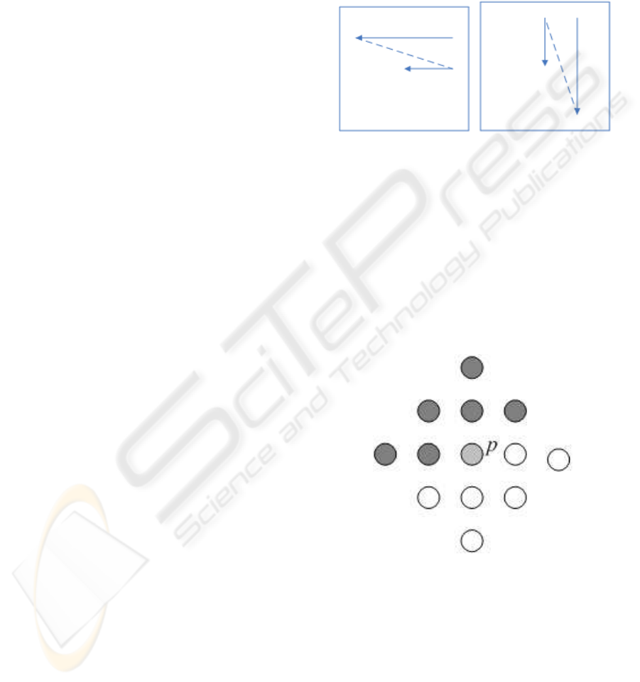
Take the top-right corner as an example as shown in
Figure 3, the recovery process starts from the pixels in
the top-right corner, there are two directions to reach
the diagonal corner. In Figure 3(a), it recovers the
missing pixels with the direction from right to left for
each line and repeats the process till the bottom-left
corner. The missing block will be recovered using
patch-based inpainting in each determined direction.
3.2 Patch-based Inpainting
For each determined recovery order, the patch-based
inpainting algorithm uses patch-wise similarity within
the image to reconstruct the missing block.
The missing block is referred to as the unknown
area, denoted by Ω. The area will now be filled, pixel
by pixel, in a raster fashion. The known area, denoted
by Φ, provides samples used in the filling process. Let
Ψ denote the patch. The patch may be a square, rect-
angle, triangle, or any other shape, and all the pixels
within the patch are contiguously connected.
In this paper, the patch centered at the pixel p
0
=
(i, j) is here defined to be a diamond shaped window,
as:
Ψ(p
0
) = {p = (x, y), 0 ≤ (|x−i| + |y− j|) ≤ T
0
} (1)
where T
0
is the order of the patch, which controls
the size of the patch. A target patch with T
0
= 2 is
shown in Figure 4, where the light-gray pixel p is the
current pixel to be recovered, and the dark-gray pixels
represent the available pixels, available means uncor-
rupted or recovered, the white pixels are the missing
pixels. A source patch is the corresponding area in Φ,
which has the same shape and size as the target patch.
(a) (b)
Figure 3: Textural and edge images.
To recover the lost pixels, a search procedure is
applied within a large range in the image. The pur-
pose of the search procedure is to find a source patch
in the image that has the best similarity with the target
patch. We then replace the current pixel being filled in
the lost block by the value of the corresponding pixel
of the best matched source patch, as shown in Figure
5. Then we recover the rest of pixels using the same
approach under the mentioned recovery order.
Figure 4: Target patch with the order of 2.
The similarity of the source patch and the target
patch is measured by the normalized sum of absolute
differences. Since it is desirable to give more impor-
tance to the pixels that are uncorrupted than those re-
covered previously, different weights are taken for the
two kinds of pixels. The pixels within the patch that
have not been recovered yet are not taken into account
in the distance. The distance between the source patch
and target patch can thus be expressed as:
ADAPTIVE PATCH-BASED INPAINTING FOR IMAGE BLOCK RECOVERY
55
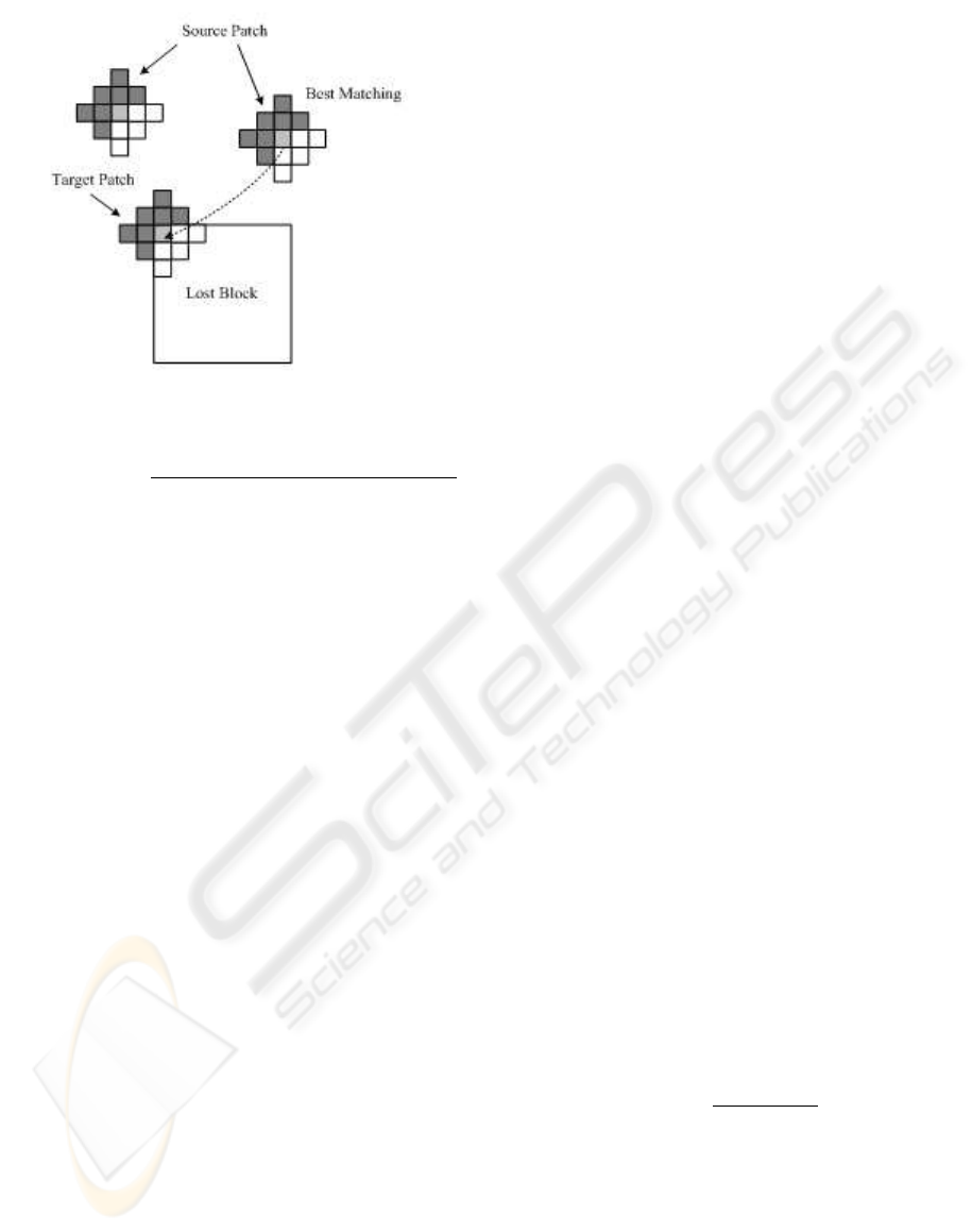
Figure 5: Pixel recovery.
d(Ψ(p
s
), Ψ(p
t
)) =
∑
q∈Ψ(q
0
)
a(p
t
+ q)| f(p
s
+ q) − f(p
t
+ q)|
∑
q∈Ψ(q
0
)
a(p
t
+ q)
(2)
where p
s
and p
t
are the centers of the source patch
Ψ(p
s
) and the target patch Ψ(p
t
), respectively, f (p)
is the value of the pixel p, Ψ(q
0
) is the diamond win-
dow defined in (1) and q
0
= (0, 0), The weight map
a(p) is assigned for each pixel in target patch, as fol-
lows:
a(p) =
1, p is uncorrupted
0.5, p is revcovered
0, p is lost
(3)
The recovered pixel has some distortion and is
given a lower weight compared with the uncorrupted
one. And a(p) is set to 0.5 for the recovered pixel,
experimentally.
In summary, the patch based inpainting algorithm
for single directional recovery proceeds as follows:
1. Choose a pixel to be recovered in Ω as current
pixel according to the predetermined recovery or-
der, such as that in Figure 3(a).
2. Get the target patch Ψ(p
t
) centered by the cur-
rent pixel, and search as the best matching
source patch Ψ(p
s
) with Ψ(p
t
) , which minimizes
d(Ψ(p
s
), Ψ(p
t
)). In this paper, the search range is
selected as 32× 32.
3. Copy the pixel in the center of the source patch to
the current pixel. Alternatively, in order to accel-
erate the computation, we can fill all the unknown
pixels in the target patch by the corresponding
pixels in the source patch. In this case, the com-
putation will be decreased significantly with ac-
ceptable reduction of the performance.
4. Repeat steps 1, 2, and 3 until all the lost pixels are
filled.
3.3 Combination Strategy
In single-directional inpainting, the error of restored
pixels will increase along the recovery direction be-
cause of unconfident recovered pixel results. Dif-
ferent recovery orders may introduce different error
propagation patterns. The error from one recovery or-
der can be compensated by results from the other or-
der. Therefore, we can reconstruct the image through
merging the result from different recovery orders as:
p =
8
∑
n=1
w
n
(p) f (p
n
) (4)
where w
n
(p) is the weighting coefficient control-
ling the contribution of the n
th
recovery order for the
pixel p, and f(p
n
) is the value of the recovered pixel
in the n
th
order.
In this paper, the weight is associated with the
confidence of the recovery performance in a specific
recovery order. The confidence consists two items:
similarity confidence S
n
(p) and reliablility confidence
R
n
(p).
The similarity confidence S
n
(p) can be expressed
by the Gaussian function of the Euclidean distance
between the source patch and the target patch, and we
simplified it as:
S
n
(p) = 2
−αd
∗
(Ψ(p
s
),Ψ(p
t
))
(5)
where d
∗
(Ψ(p
s
), Ψ(p
t
)) is the difference between
the target patch and the best match source patch,
which is defined in (2), and the parameter α regulates
the relative influence of the difference on the weights.
It is set to 0.125, experimentally.
The reliability confidence R
n
(p) measures the
amount of reliable information surrounding the pixel
p. Our aim is to give higher weight to the pixel whose
patch has more pixels which are known or have al-
ready been recovered. R
n
(p) is defined as:
R
n
(p) =
∑
q∈Ψ(p)
R
n
(q)
A(Ψ(p))
(6)
where Ψ(p) is the target patch centered on the
pixel p, A(Ψ(p)) is the area of the patch Ψ(p), i.e.
the number of pixels in the patch. Initially, we define
R
n
(p) = 0 if p is a missing pixel, R
n
(p) = 1 if not.
For each pixel p to be recovered, we define its
weight for a specific recovery order associated with
the product of above two terms:
w
n
(p) ∝ S
n
(p)R
n
(p) (7)
VISAPP 2010 - International Conference on Computer Vision Theory and Applications
56
The weighting provides an efficient and flexible way
to select the appropriate pixels contributing to the es-
timation of the lost pixel for the final result.
We compute the confidence for all the recovery
order for each lost pixel, and normalize the weight
coefficients as:
w
n
(p) =
S
n
(p)R
n
(p)
8
∑
k=1
S
k
(p)R
k
(p)
(8)
After obtaining these weight coefficients, we recover
the lost pixels through combining the intermediate re-
sults from all the recovery orders.
4 EXPERIMENT RESULTS
In order to illustrate the performance of our error re-
covery method, we take many experiments on test im-
ages: Lena, Baboon, Pepper and Barbara. We con-
sider the situation of the 16× 16 block since the im-
age or video are often encoded in 16× 16 block size.
Different block-loss situations are investigated in the
paper: isolated block loss and consecutive block loss.
For objective evaluation, we use a modified peak
signal-to-noise ratio (PSNR) as the objective measure
in our experiments, which is defined just on the cor-
rupted areas instead of the entire image:
PSNR = 10log
10
255
1
M
∑
p∈Ω
( f
0
(p) − f
r
(p))
(9)
where f
o
(p) and f
r
(p) are the pixel values in the
original and the recovered image, and M is the num-
ber of the lost pixels. We first give the implementation
details in our experiments and then compare it with
several existing error recovery algorithms.
4.1 Implementation Details
For the implementation of the proposed algorithm,
there remain some choices, which include the follow-
ing:
1. The patch size. The size of the patch affects how
well the filled pixels capture the local characteris-
tics of the known region. The patch size is con-
trolled by T
0
, which is defined in (1).
2. The filling manner. The filling manner means
whether the pixel centered on the target patch
(pixel-filling) or the unknown part of the target
patch (patch-filling) will be filled in the step 3 of
the patch based inpainting algorithm.
In the first experiment, we illustrate how the choice
of patch size affects the recovery performance. We
fix the search range as 32× 32 with pixel-filling. And
we investigate the isolated block loss situation with
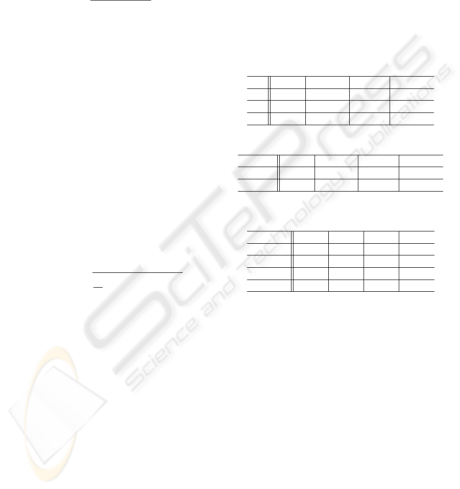
about 10% loss rate. Table 1 shows the evolution of
PSNR values with different patch size using pixel-
filling. Smaller patch size allows more matching pos-
sibilities, thus implies weaker statistical constraints.
Up to a certain limit, bigger patch size can capture
the texture characteristics better, however with much
higher computation complexity. From the results in
Table 1, T
0
= 2 is a good balance.
Table 1: The impact of patch size for block loss (dB).
T
0
Lena Baboon Pepper Barbara
1 26.63 20.94 28.34 24.13
2 27.35 21.25 29.10 26.01
3 27.33 21.24 29.31 26.40
Table 2: The impact of patch size for block loss (dB).
Filling Lena Baboon Pepper Barbara
Pixel 27.35 21.25 29.10 26.01
Patch 27.06 20.88 28.12 25.94
Table 3: Performance comparison for isolated block loss
(dB).
Image BI OI OASI Ours
Lena 24.03 23.74 25.98 27.35
Baboon 20.25 18.46 20.16 21.25
Pepper 24.85 24.34 26.67 29.10
Barbara 20.69 21.62 22.84 26.01
In the second experiment, we demonstrate the im-
pact of the filling manner on the recovery perfor-
mance. Table 2 shows the performance of the two
different filling manners with T
0
= 2. It can be seen
that pixel-filling shows better performance than the
patch-filling and the gap ranges from 0.07 to 0.98 dB.
4.2 Comparison Results
To demonstrate the effectiveness of our algorithm, we
compare it with several previous existing error recov-
ery algorithms: bilinear interpolation (BI), the ori-
entation adaptive sequential interpolation (OASI) (Li
and Orchard, 2002), order-based inpainting (OI) (Cri-
minisi and Perez, 2003). For our algorithm, in the
experiment, we set T
0
= 2 and use pixel-filling man-
ner in the recovery process.
Table 3 and Table 4 give the PSNR comparisons
between the compared methods and our algorithm
under the following two loss situations: the isolated
block loss (about 10%) and consecutive block loss
ADAPTIVE PATCH-BASED INPAINTING FOR IMAGE BLOCK RECOVERY
57
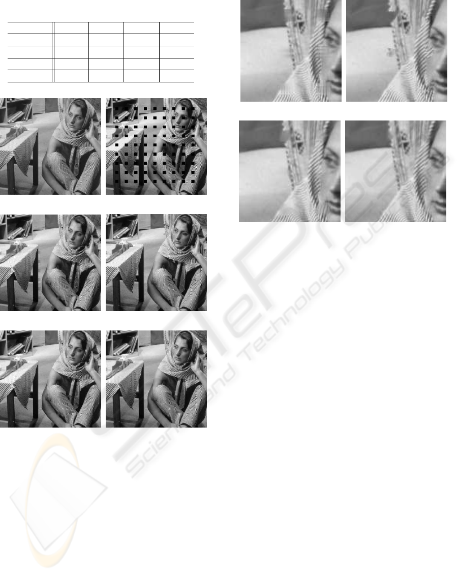
Table 4: Performance comparison for consecutive block
loss (dB).
Image BI OI OASI Ours
Lena 22.21 21.32 22.07 24.21
Baboon 19.15 17.94 19.08 20.24
Pepper 25.22 23.26 24.00 26.05
Barbara 19.98 18.21 20.06 23.11
(a) Origin (b) Corrupted
(c) Bilinear Interpolation (d) Order-based Inpainting
(e) OASI (f) Our Method
Figure 6: Reconstructed images for Barbara for isolate
block loss.
(about 25%). It can be seen that we have achieved
1.09-3.17 dB improvement in the case of isolated
block loss and 1.16-3.05 dB improvement in the case
of consecutive block loss over OASI. To subjectively
evaluate the results, Figure 6 shows the comparison
of the reconstructed images for Barbara by the com-
pared methods and our algorithm in the situation of
isolated block loss. It can be observed that our new
approach has achieved significant improvements in
the area of complex texture structures. For better sub-
jective evaluation, we show some enlarged examples
for sharp edge areas, texture areas and very complex
areas in Figure 7. The visual quality of the recov-
(a) Bilinear Interpolation (b) Order-based Inpainting
(c) OASI (d) Our Method
Figure 7: Enlarged part of the images in Figure 6.
ered blocks are very good even when the areas con-
tain a lot of detail information. Figure 8 shows the
comparison of the reconstructed images for Lena by
the compared methods and our technique in the situa-
tion of consecutive block loss. Significant improve-
ments can be found in the recovered image by the
proposed method, especially on the blocks with the
strong edges or complex texture. And the similar re-
sults are obtained for other test images.
5 CONCLUSIONS
In this paper, we present an adaptive patch-based in-
painting algorithm for image block recovery in block-
based coding image transmission. The proposed ap-
proach is based on a prior information - patch simi-
larity within the image. By taking advantage of the
information, we recover the lost pixels by copying
pixel values from the source based on a similarity cri-
terion to keep local continuity. The pixel recovery is
performed in a sequential fashion in which the recov-
ered pixels can be used in the recovery process after-
wards. In order to alleviate the error propagation with
sequential recovery, we proposed an adaptive combi-
nation strategy which merges different directional re-
covered pixels according to the confidence of the es-
timated recovery performance. Experimental results
show that the proposed method provides significant
improvements in terms of both subjective and objec-
tive evaluations.
VISAPP 2010 - International Conference on Computer Vision Theory and Applications
58
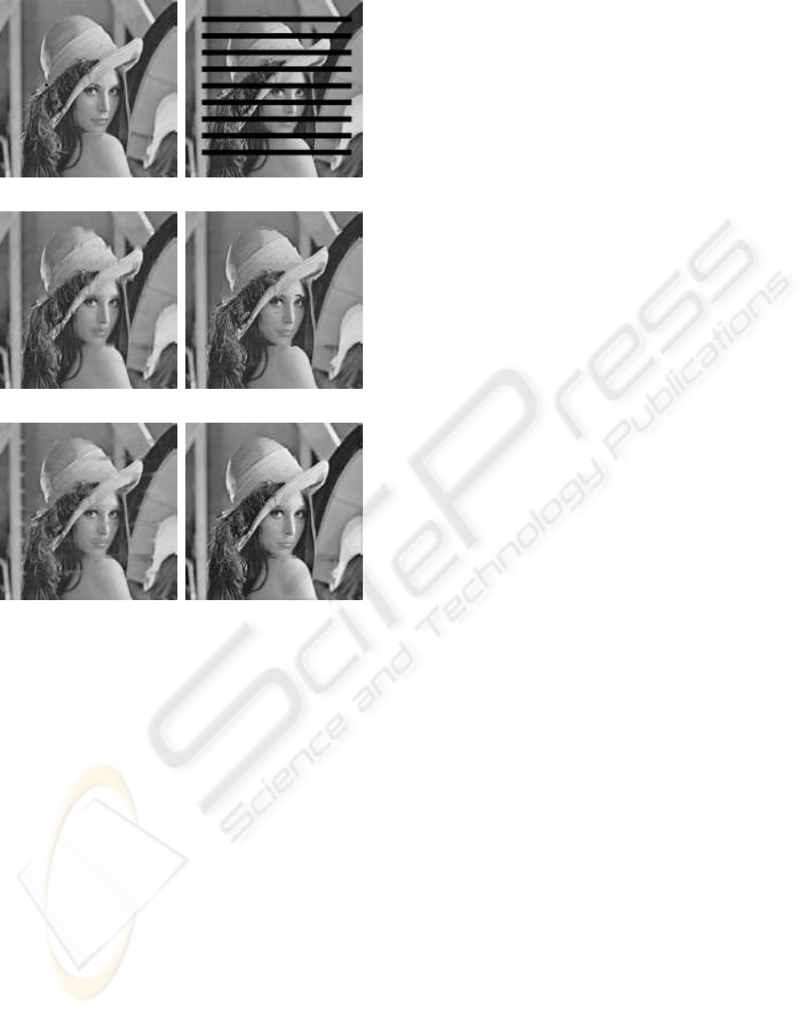
(a) Origin (b) Corrupted
(c) Bilinear Interpolation (d) Order-based Inpainting
(e) OASI (f) Our Method
Figure 8: Reconstructed images for Lena for consecutive
block loss.
ACKNOWLEDGEMENTS
The authors deeply appreciate the constructive sug-
gestions and insightful comments from Prof. Vicent
Caselles.
REFERENCES
Agrafiotis, D., Bull, D., and Canagarajah, C. (2006). Error
resilient video coding techniques. IEEE Trans. Cir-
cuits Syst. Video Technol., 16(8):960–973.
Arias, P., Caselles, V., and Sapiro, G. (2009). Varia-
tional framework for non-local image inpainting. In
Proc.EMMCVPR, pages 345–358, Bonn, Germany.
Bertalmio, M., Sapiro, G., Caselles, V., and Ballester, C.
(2000). Image inpainting. In Proc. Computer Graph-
ics (SIGGRAPH 2000), pages 417–424.
Bertalmio, M., Vese, L., Sapiro, G., and Osher, S. (2003).
Simultaneous structure and texture image inpainting.
IEEE Trans. on Image Processing, 12(8):882–889.
Chan, T. and Shen, J. (2001). Mathematical models for
local nontexture inpainting. SIAM J. Appl. Math.,
62(3):1019–1043.
Criminisi, A. and Perez, P. (2003). Object removal by
exemplar-based inpainting. In Proc. Int. Conf. Comp.
Vision Pattern Rec., pages 721–728, Madison, WI.
Efros, A. and Leung, T. (1999). Texture synthesis by non-
parametric sampling. In Proc. Int. Conf. Computer
Vision, pages 1033–1038, Kerkyra, Greece.
Gao, Y., Wang, J., Liu, Y., Yang, X., and Wang, J.
(2007). Spatial error concealment technique using
verge points. In Proc. IEEE ICASSP, pages 309–312,
Honolulu, HI.
Hong, M. C., Scwab, H., Kondi, L., and Katsaggelos, A. K.
(1999). Error concealment algorithms for compressed
video. Signal Processing: Image Communication,
14:473–492.
Kim, W., Koo, J., and Jeong, J. (2006). Fine directional in-
terpolation for spatial error concealment. IEEE Trans.
Consumer Electronics, 52(3):1050–1055.
Kung, W.-Y., Kim, C.-S., and Kuo, C.-C. J. (2006). Spatial
and temporal error concealment techniques for video
transmission over noisy channels. IEEE Trans. Cir-
cuits Syst. Video Technol., 16:789–802.
Li, X. and Orchard, M. T. (2002). Novel sequential error-
recovery techniques utilizing orientation adaptive in-
terpolation. IEEE Trans. Circuits Syst. Video Technol.,
12(10):857–864.
Rane, S. D., Remus, J., and Sapiro, G. (2002). Wavelet-
domain reconstruction of lost blocks in wireless im-
age transmission and packet-switched networks. In
Proc.IEEE ICIP, pages 309–312, Rochester, NY.
Sullivan, G. J. and Wiegand, T. (2005). Video compression
- from concepts to the H.264/AVC standard. Proceed-
ings of the IEEE, 93(1):18–31.
Wang, Y., Hannuksela, M. M., Varsa, V., Hourunranta, A.,
and Gabbouj, M. (2002). The error concealment fea-
ture in the H.26L test model. In Proc. IEEE ICIP,
pages 729–732, Rochester, NY.
Wang, Y., Wenger, S., , and Katsaggelos, A. K. (2000). Er-
ror resilient video coding techniques. IEEE Signal
Processing Mag., 17(4):61–82.
Wang, Y. and Zhu, Q.-F. (1998). Error control and conceal-
ment for video communication: A review. Proceed-
ings of the IEEE, 86(5):974–997.
Wang, Z., Yu, Y., and Zhang, D. (1998). Best neighborhood
matching: An information loss restoration technique
for block-based image coding systems. IEEE Trans.
on Image Processing, 7(7):1056–1061.
ADAPTIVE PATCH-BASED INPAINTING FOR IMAGE BLOCK RECOVERY
59
