
INTERACTIVE DESIGN AND DEBUGGING
OF GPU-BASED VOLUME VISUALIZATIONS
Jennis Meyer-Spradow, Timo Ropinski, J
¨
org Mensmann and Klaus Hinrichs
Visualization and Computer Graphics Research Group (VisCG), University of M
¨
unster, Germany
Keywords:
GPU-based volume rendering, Visual programming, Data flow networks.
Abstract:
There is a growing need for custom visualization applications to deal with the rising amounts of volume data
to be analyzed in fields like medicine, seismology, and meteorology. Visual programming techniques have
been used in visualization and other fields to analyze and visualize data in an intuitive manner. However, this
additional step of abstraction often results in a performance penalty during the actual rendering. In order to
prevent this impact, a careful modularization of the required processing steps is necessary, which provides
flexibility and good performance at the same time. In this paper, we will describe the technical foundations
as well as the possible applications of such a modularization for GPU-based volume raycasting, which can
be considered the state-of-the-art technique for interactive volume rendering. Based on the proposed mod-
ularization on a functional level, we will show how to integrate GPU-based volume ray-casting in a visual
programming environment in such a way that a high degree of flexibility is achieved without any performance
impact.
1 INTRODUCTION
In many domains the amount of volume data is ris-
ing due to new or refined sensing and simulation tech-
nologies and the more widespread use of data acquisi-
tion techniques. For example, well established imag-
ing techniques such as computed tomography (CT)
and magnetic resonance imaging (MRI) and more
recent functional imaging techniques like positron
emission tomography (PET) are increasingly used in
daily medical routine. In addition, due to the om-
nipresence of volume data and the increasing familiar-
ity with these data the problems posed and the ques-
tions asked by the users become more and more com-
plex.
To answer such a question often new visualiza-
tion techniques need to be designed. Many mod-
ern volume visualizations employ GPU-based ray-
casting (Kr
¨
uger and Westermann, 2003), which can
be considered the state-of-the-art technique for ren-
dering volumetric data. Its main advantages are the
high flexibility and the achieved image quality. By
utilizing modern graphics processing units (GPUs)
for all computations performed during the ray traver-
sal, interactive frame rates are achievable even when
applying quite complex effects. However, graphics
programming and especially GPU programming is
complex, error-prone, and time-consuming.
Applications intended for the design of new vi-
sualization techniques often use visual programming
paradigms in order to manage the described complex-
ity. The rendering process is decomposed into func-
tional components which can be flexibly arranged in
data flow networks. Since usually this decomposition
is done on a rather high level, the resulting entities
are quite complex, e. g., a component which performs
a complete GPU-based volume raycasting. This level
of abstraction results in rather general components,
which consequently leads to reduced performance.
In this paper, we present a careful modularization
of the GPU-based volume raycasting process and its
realization on current graphics hardware. By decom-
posing the raycaster itself into small-grained func-
tional components (called processors), we are able to
exploit the visual programming paradigm on a lower
level and are thus able to achieve unbiased rendering
performance. By introducing the visual programming
concept to low-level GPU-rendering, we are able to
transparently interweave it with the visual program-
ming concepts used on a higher level, e. g., for appli-
cation prototyping. Thus, complex visualization ap-
plications can be generated exploiting a single perva-
sive visual programming paradigm, which gives full
control on the application level as well as the GPU
239
Meyer-Spradow J., Ropinski T., Mensmann J. and Hinrichs K. (2010).
INTERACTIVE DESIGN AND DEBUGGING OF GPU-BASED VOLUME VISUALIZATIONS.
In Proceedings of the International Conference on Computer Graphics Theory and Applications, pages 239-245
DOI: 10.5220/0002832302390245
Copyright
c
SciTePress
level. The latter is essential in order to generate
applications, which can visualize today’s data sets at
interactive frame rates. To further support the rapid
development of such applications, we introduce vi-
sual debugging functionality, which gives access to
intermediate results otherwise not accessible in the fi-
nal application. All the described concepts are avail-
able as open source within the Voreen
1
volume ren-
dering engine (Meyer-Spradow et al., 2009). Within
this framework, new visualization applications can be
generated in the development mode, in which the user
has full access to all available processors, the under-
lying data flow network as well as a preview visual-
ization (see Figure 1 (a)). To test these applications,
the visualization mode can be used, which gives only
access to the user interface components specified by
the application developer (see Figure 1 (b)). In the re-
mainder of this paper, we will describe the proposed
modularization of the GPU-based volume raycasting
and demonstrate the implications on the application
development.
2 RELATED WORK
The analysis and visualization of volume data has
become a frequent task for scientists, and therefore
many libraries, applications, and rapid prototyping
environments (RPEs) are available. Since the use
of libraries requires extensive programming skills
and applications are limited to built-in tasks, RPEs
are very popular. They often use visual program-
ming (Johnston et al., 2004) to let the user graph-
ically combine objects in order to achieve the de-
sired goals. All concepts described in this paper
are realized within the Voreen volume rendering en-
gine (Meyer-Spradow et al., 2009), which is freely
available.
The established RPEs like Amira (Stalling et al.,
2005), AVS/Express (Hewitt et al., 2005), Mevis-
Lab (Rexilius et al., 2006), SCIRun (Weinstein et al.,
2005), and VisTrails (Bavoil et al., 2005) focus on
the entire process of analyzing data; the visualiza-
tion is only the final step and in some systems even
a minor aspect. Mostly slice-based methods are used
for the visualization of volumetric data which have
algorithm-immanent disadvantages such as less flexi-
bility and worse image quality in comparison to ray-
casting. MevisLab also provides a GPU-based ray-
casting block which supports reconfiguration of the
renderer on a per-object basis (Link et al., 2006),
but it does not allow to decompose the raycaster.
1
www.voreen.org
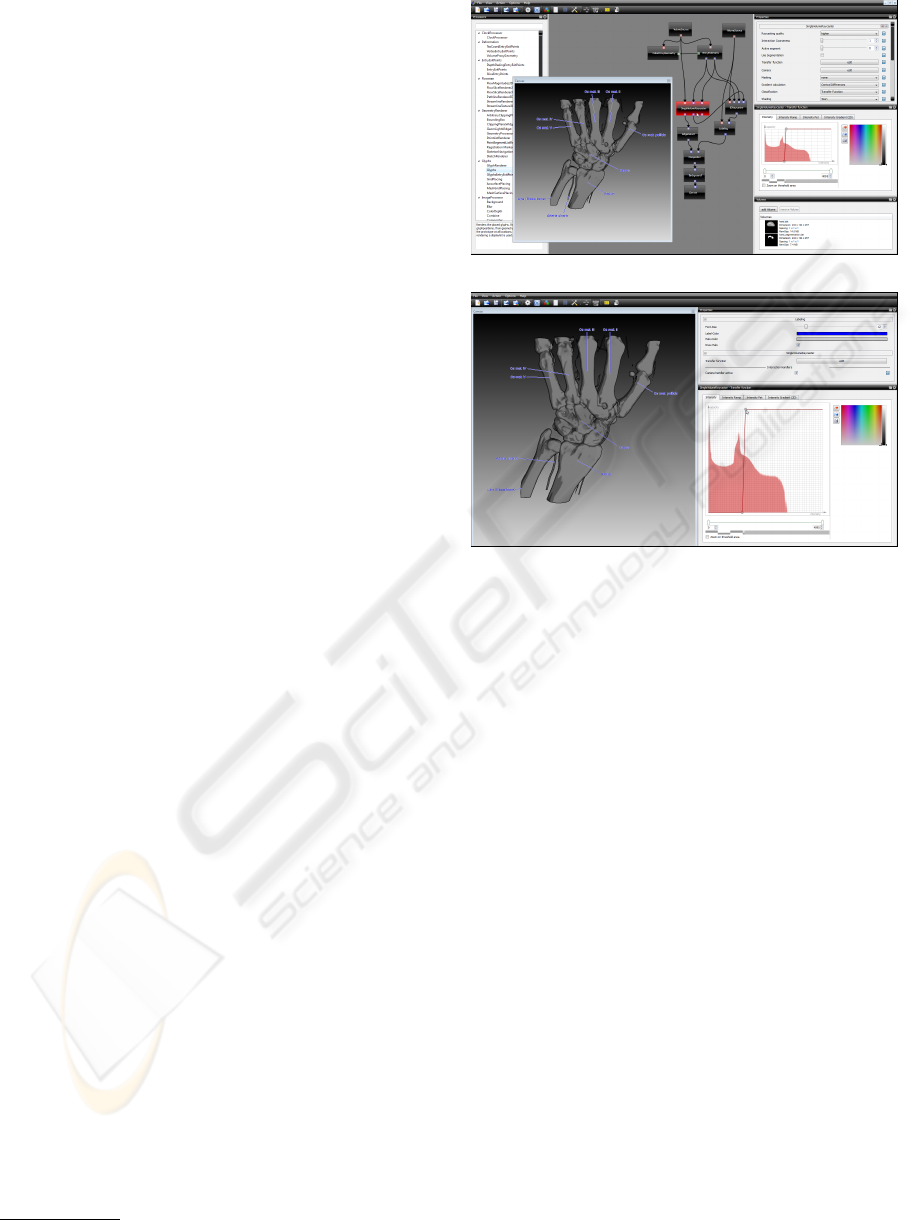
(a) development mode.
(b) visualization mode.
Figure 1: Visual programming is possible on multiple lev-
els of abstraction: in the development mode, the user can
modify the data flow network and choose, which properties
are editable in the visualization mode. In the visualization
mode only these properties are shown while the data flow
network is hidden.
Furthermore, the relatively new open source RPE
XIP (Prior et al., 2007) also uses only slicing for
volumetric rendering. Overviews and comparisons
of some of these packages are given in (Hahn et al.,
2003; Bitter et al., 2007). Caban et al. compared sev-
eral open-source libraries and applications in (Caban
et al., 2007). Botha presented an RPE in his PhD
thesis (Botha, 2005); a special feature is the hybrid
scheduling approach which supports event-driven as
well as demand-driven scheduling (Botha and Post,
2008). It uses the VTK library for visualization which
supports slicing only.
A rendering framework for using different
GPU-based raycasting techniques is presented
in (Stegmaier et al., 2005), it provides some basic
functionality and achieves its flexibility by replacing
the shaders. Since raycasting is not split into sub-
tasks, the advantage of combining small blocks is
missing. R
¨
oßler et al. present a framework (R
¨
oßler
et al., 2008) which allows the dynamic creation of a
volume rendering graph. Specific fragment programs
are derived from the graph to obtain and combine
GRAPP 2010 - International Conference on Computer Graphics Theory and Applications
240

various GPU-based rendering techniques. However,
these systems only focus on the shader development
and do not provide the visual programming paradigm
on all abstraction levels. Plate et al. introduced
a framework for rendering arbitrarily intersecting
volumes with the support of volume lenses (Plate
et al., 2007). Each configuration is tiled into convex
regions, which are rendered separately using a
slicing algorithm. By using a graphical editor each
region can be treated individually, and the resulting
renderings are combined into the final image.
To summarize, several visual programming envi-
ronments support modularized data processing, but to
the best of our knowledge there is no one which pro-
vides a sufficient interweaving of GPU programming
and application development, which is essential in or-
der to generate interactive applications used for visual
exploration.
3 ENABLING MULTI-LEVEL
VISUAL PROGRAMMING
In this section, we describe our modularization
of GPU-based raycasting (Kr
¨
uger and Westermann,
2003), which allows to apply the visual programming
paradigm on multiple abstraction levels in order to
generate high-quality interactive visualization appli-
cations. GPU-based raycasting can be considered the
state-of-the-art technique for interactive volume ren-
dering. For each screen pixel a ray is cast from the
virtual camera through the pixel into the scene, and
the emission and absorption characteristics of each
voxel intersecting the ray are calculated. In general, a
voxel’s intensity is not used directly, but as an argu-
ment of a color and transparency transfer function.
The rendering is performed on the graphics pro-
cessing unit (GPU), the volume data is stored in a
3D volume texture. Since knowledge about the con-
cepts behind GPU-based volume raycasting is essen-
tial, we briefly review the technique. A proxy geom-
etry is used to represent the geometric shape of the
data set. For each ray the intersection points with
the proxy geometry, i. e., an entry point and an exit
point, have to be determined. To do this, the color
parameters of the vertices of the proxy geometry are
initialized with the (color-coded) coordinates neces-
sary for fetching the voxels from the 3D texture. In
order to calculate the entry points the proxy geome-
try is transformed into the current view, rendered, and
the result is stored in a 2D texture. Due to the ini-
tial color-coding of the vertices of the proxy geom-
etry, during rendering the GPU’s color interpolation
unit automatically produces for each pixel’s ray the
color-coded position information of its entry point.
The exit points are created in a second pass by render-
ing only the back-faces. During the subsequent ray-
casting performed within a fragment shader, the entry
and exit points are used to calculate a ray’s direction
and length.
In our system, complex volume visualizations can
be composed by visually combining several func-
tional building blocks called processors, each per-
forming a specific task. Data, such as images and vol-
umes, flow between the processors, i. e., the output of
one processor is transferred as input to one or more
other processors through processor ports. Inports are
used for input and outports for output. Different types
of ports are defined to determine which inport/outport
pairs are compatible and thus can be connected for
transfer. Typical port types allow to transfer volume,
image, or geometry data. So far several processors
exist for processing volumes or images, similar as in
the systems discussed in Section 2. However, addi-
tionally we have transferred the processor concept to
the GPU level, by decomposing GPU-based raycast-
ing into separate processors, which can be combined
flexibly without. The challenge of this decomposition
is to gain flexibility through abstraction by still allow-
ing interactive frame rates, which requires to incorpo-
rate the boundary conditions of GPU programming.
Furthermore, our decomposition leads almost auto-
matically to an object-oriented design: processors are
objects, they encapsulate information, and inheritance
can be used to extend their functionality. However,
the architecture of the underlying graphics system,
OpenGL, is not object-oriented. For efficiency rea-
sons OpenGL’s state is determined by global vari-
ables, and polygonal data or textures are accessible
via references from anywhere within an OpenGL pro-
gram. Encapsulating such data into objects would re-
sult in a significant loss of performance. Thus, we had
to carefully trade-off between achieving high graphics
performance and following guidelines for pure object-
oriented design.
3.1 Decomposing GPU-based
Raycasting
We have decomposed the raycasting process into
three modules: proxy geometry management (PGM),
entry and exit point generation (EEPG), and the ac-
tual ray traversal (RT). The EEPG uses the PGM to
create entry and exit point textures from which the RT
processor fetches the entry point and the exit point for
each ray and performs the raycasting. This decompo-
sition gives us a flexibility on the GPU level, which
allows to reuse as well as adapt selected functional-
INTERACTIVE DESIGN AND DEBUGGING OF GPU-BASED VOLUME VISUALIZATIONS
241
ities. Thus, for each of these three components dif-
ferent implementations can be generated which per-
form specific tasks. For instance, by modifying the
proxy geometry, the part of the volume data to be
visualized can be changed. An example is apply-
ing clipping planes to a cuboid-shaped proxy geom-
etry. This leaves a clipped proxy geometry, and the
entry and exit points are adjusted automatically be-
cause they are calculated using the color-coded posi-
tions of the changed vertices. More complex effects
can be achieved by applying a proxy geometry pro-
cessor which uses a more elaborate mesh represen-
tation for the proxy geometry and relaxes the rela-
tion between vertex positions and colors. Thus, keep-
ing the colors constant and changing the vertex posi-
tions can produce a rendering of a deformed volume.
Similarly the EEP generation can be modified to pre-
pare a volume rendering for the integration of polyg-
onal objects, e. g., glyphs. Assuming that the polyg-
onal objects are opaque, it is sufficient to initialize
the colors of the vertices with their positions (in tex-
ture coordinates—just the same as in the PGM) and
render them onto the exit point image. Rays which
intersect such polygonal objects will terminate at the
foremost intersection points, and the resulting volume
rendering can be combined later with an image of the
polygonal objects.
Thus, the raycasting process is split into mainly
three functional components, which have been real-
ized as individual C++ classes. Instances of these
classes form the processor network. To propagate the
decomposition further towards the GPU, the proces-
sors themselves are also decomposed into combinable
functional modules, which can be realized through
shader code. For instance, the ray traversal proces-
sor uses a GLSL fragment shader for the actual com-
putations. This shader code is separated into logical
tasks whose replacement might be desired. Thus, we
are for instance able to easily change the compositing
without affecting the rendering performance. In the
following subsection we describe this decomposition
on a shader level.
3.2 Modularization of the Ray Traversal
In order to identify the necessary logical units, we
have analyzed several shader implementations and
identified four points in which they typically differ:
• Gradient calculation: gradients can be calcu-
lated with different methods or pre-calculated
ones can be used; possibly a visualization method
does not need any gradients.
• Transfer function: a transfer function can be one
or multi dimensional; some visualization methods
1 vec4 r ayT ra ver sa l ( in vec3 first , in vec3 la st )
2 {
3 vec4 result = vec4 (0 .0 ) ;
4
5 // calculate ray parameters
6 float t Inc r , tE nd ;
7 vec3 rayDir ;
8 raySe tu p ( first , las t , r ayDi r , tI ncr , tE nd ) ;
9
10 float t = 0 .0 ;
11 RC_ BE GIN _L OOP {
12 vec3 sam pl eP os = f ir st + t* ra yD ir ;
13 vec4 vo xe l = get Vo xe l ( vol_ , vo lP ar am s_ ,
14 sam pl eP os );
15
16 // calculate gradients
17 vo xe l . xy z = RC_ CA L C_ GRA DI E NT S ( v ox el . xyz ,
18 sa mp le Po s , vol_ , vo lP ar am s_ ,
19 t , r ayDi r , e nt ryPts _ );
20
21 // apply classification
22 vec4 co lo r = R C_ A PL _CL ASS IF I CA TIO N ( v ox el ) ;
23
24 // apply shading
25 co lo r . rg b = RC_ AP L_S HA DIN G ( v oxel . xyz ,
26 sa m p l e P o s , volParams_ ,
27 colo r . rgb , color . rgb ,
28 colo r . r gb ) ;
29
30 // if opacity greater zero,
31 // apply compositing
32 if ( c o l o r . a > 0 .0)
33 result = R C_ A P L_ C O MP O S I T I N G ( r esul t ,
34 color , sa m p l e P o s , voxel . xyz ,
35 t, tDepth ) ;
36 }
37 RC _ E N D_L O O P ( resu l t ) ;
38 return result ;
39 }
Listing 1: The generic fragment program for ray traversal.
The methods named RC * are replaced at shader compile
time with specialized methods.
may use the intensity values directly without us-
ing a transfer function.
• Shading: the shading can be calculated in differ-
ent ways (local, local with shadows, global); some
visualizations do not need any shading.
• Compositing: the compositing determines how
the current value will be combined with the al-
ready calculated ones, e. g., DVR differs from
MIP.
By providing different alternatives for one or more
of these functional blocks a lot of flexibility can be
GRAPP 2010 - International Conference on Computer Graphics Theory and Applications
242
gained. An obvious solution is to implement for
each alternative a separate function, which is exe-
cuted at runtime. However, when introducing such a
degree of abstraction, the limitations of GPUs have
to be taken into account in order to achieve good
performance results. For instance, a switch-case
block (resp. an equivalent if-else if structure since
GLSL does not support the former) in each case
would be the straight-forward but unacceptable solu-
tion, since due to the branching this would be excep-
tionally time-consuming on GPUs. Since OpenGL
shader programs are not compiled together with the
host program during application development but by
the graphics driver at runtime of the application, we
have decided to generate the shader from arbitrary
components at runtime. In contrast to using uni-
forms, this approach is especially beneficial when
dealing with changes occurring at a low frequency.
Listing 1 shows the fragment program skeleton we
use. Method placeholders can be replaced at runtime
with specific versions that begin with the prefix RC .
The #define directive of GLSL is used for defining
macros for these placeholders.
This approach gives us the flexibility to replace
function calls during runtime. To still achieve a com-
prehensive shader, which is not fraught by all defined
alternatives for a function, we have extended GLSL
with an #include directive known from the C prepro-
cessor in order to be able to store different implemen-
tations of the methods in separate files. Thus we pro-
vide a set of shader includes, which define the func-
tions to be used. To illustrate the reuse of the shader
decomposition, the placeholder for the compositing
methods (lines 33–35) is specified as an example be-
low.
RC _ A PP L Y _ C O MP O S IT I N G ( r esul t , c olo r , sa m p l e P o s ,
vo x e l . xyz , t , t Depth ) ;
The parameters passed to the method contain the fol-
lowing information: result represents the accumu-
lated values of the ray traversal up to now, color is
the processed (i. e., classified and shaded) data value
of the current position, samplePos is the current ab-
solute position in the volume, voxel.xyz stores the
gradient information, t is the current position on the
ray, and tDepth contains the currently designated
depth value for this parameter. The signatures of the
implementing methods vary and depend on the inter-
nally needed variables. For DVR, MIP and isosurface
raycasting, they look as follows:
vec4 co m p osi t e DV R ( in vec4 r esul t , i n vec4 c olo r ,
in float t , in o u t float t D epth ) ;
vec4 co m p osi t e MI P ( in vec4 r esul t , i n vec4 c olo r ,
in float t , in o u t float t D epth ) ;
vec4 co m p osi t e IS O ( in vec4 r esul t , i n vec4 c olo r ,
1 hdrSrc += " # d e f ine R C _ A P P L Y _ C OM P O S I T IN G ( r esul t ,
2 color , sa m p l e P o s , grad i e n t ,
3 t, tDepth ) " ;
4 switch ( com p o s i t ing M o d e _ - > get () ) {
5 case 0:
6 hd rSrc += " c o m pos i t eDV R ( color , resu l t , t ,
7 tD e pth ) ;\ n " ;
8 break;
9 case 1:
10 hd r Src += " c o m pos i t eMI P ( color , resu l t , t ,
11 tDepth ) ;\ n ";
12 break;
13 case 2:
14 hd r Src += " c o m pos i t eIS O ( color , resu l t , t ,
15 tDept h , is o V a l u e ) ;\ n " ;
16 break;
17 }
Listing 2: Placeholders such as RC APPLY COMPOSITING
are replaced by creating a header which substitutes them
with functional methods.
in float t , in o u t float t Dep t h ,
in float is o V a l u e ) ;
All these return the composited value; changes of
other variables can be returned by declaring them
as inout as it is done for tDepth. To choose one
of these function alternatives, we generate an appro-
priate shader header, which defines the placeholder
RC APL COMPOSITING. This header is recreated by a
C++ function each time one of the replaceable func-
tions should be exchanged (see Listing 2).
The ray initialization (raySetup()) as well as the
begin and the end of the loop are also defined sepa-
rately (RC BEGIN LOOP and RC END LOOP) in order to
make them reusable in other raycasters (the variable
tDepth which is used in the compositing header is
also defined there).
4 VISUAL DEBUGGING
Debugging shader programs is complex, since besides
the general problem of debugging parallel programs
and the lack of debugging features such as break-
points, often the interplay between different proces-
sors does not work as expected. To help software en-
gineers to debug GLSL code, several GPU-oriented
debuggers such as gDEBugger (Graphic Remedy,
2010), glslDevil (Strengert et al., 2007), or Total Re-
call (Sharif and Lee, 2008) are available, which al-
low to inspect variables, to set breakpoints and so on.
INTERACTIVE DESIGN AND DEBUGGING OF GPU-BASED VOLUME VISUALIZATIONS
243
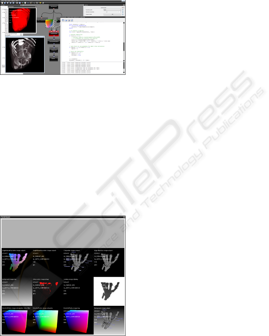
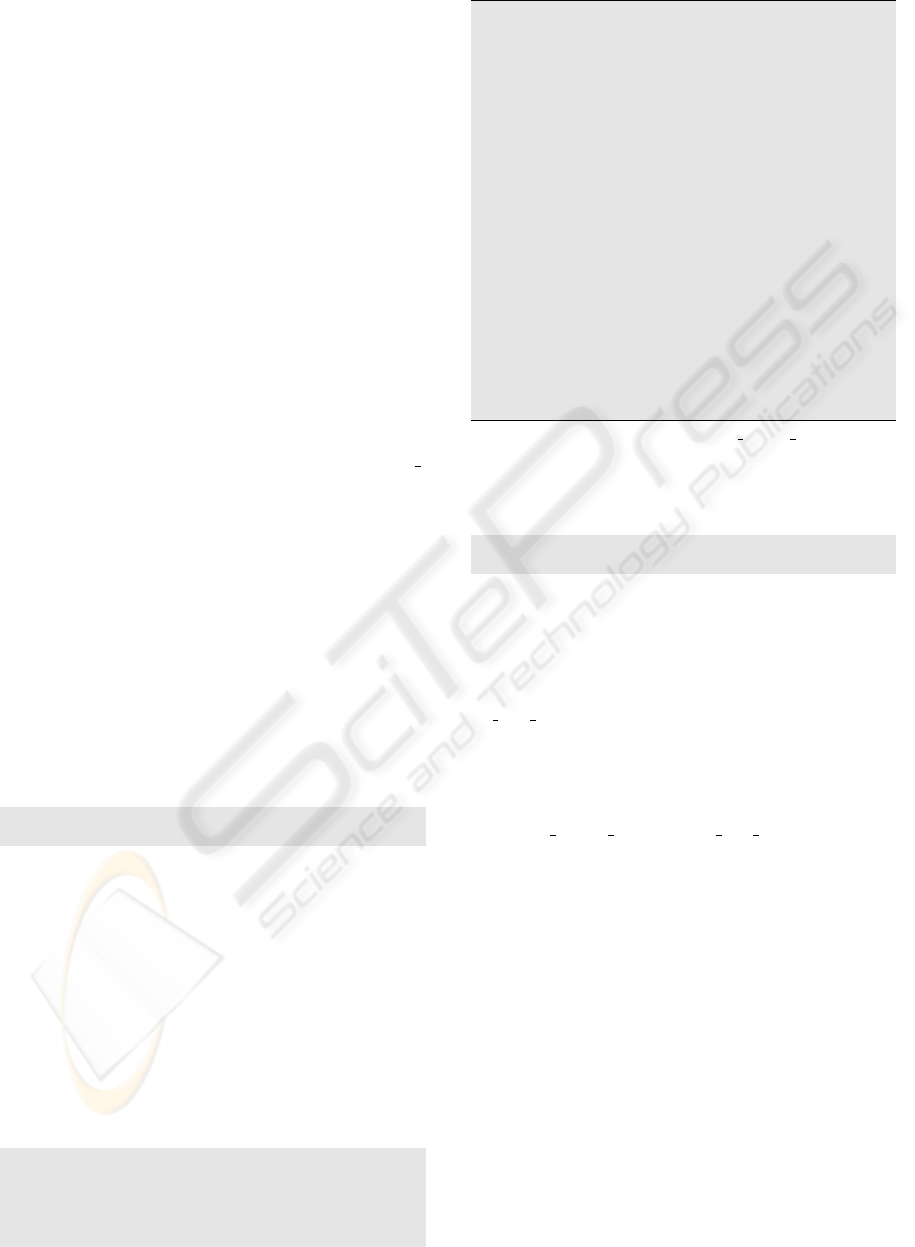
Figure 2: Shader programs can be edited in the development
mode, while shader errors can be accessed (bottom right).
Furthermore, intermediate output images can be inspected
through tooltip windows by hovering with the mouse cur-
sor over an arbitrary connection (middle) and the content of
selected rendering targets can be inspected (top left).
Our visual debugging features are not intended to re-
place such tools but rather to rapidly localize possible
bugs on a higher level by inspecting intermediate re-
sults which are created as outputs of the processors.
In a second step the conspicuous processors can then
be analyzed using one of the before mentioned pro-
grams.
We support the diagnosis of this kind of errors by
giving the user visual access to the output images of
all processors. This can be done in different ways,
either by hovering the mouse cursor over a connec-
tion between processors in the network editor where
a tooltip window then shows the image which is cur-
Figure 3: All produced images can be inspected using the
texture container window. Besides the color channels also
the alpha channel and the depth buffer can be visualized
using pseudo-colors.
rently transferred through this connection (see Fig-
ure 2), or by inspecting the texture container window
(see Figure 3). This window shows the content of all
images stored in the texture container. Each proces-
sor can label its output images and therefore makes
it possible to relate each image to the processor by
which it was generated. Furthermore, also the alpha
channel and the depth buffer can be visualized using
pseudo-colors.
Once an error is recognized it needs to be re-
solved. Since shader programs are generally com-
piled at runtime, a user can just reload the shader pro-
gram without having to restart the application. There-
fore, we have decided to integrate the used shaders
as properties of the according processors. Thus, it
becomes possible to simply edit a shader within our
environment (see Figure 2) and serialize the changes
together with the network. Thus it becomes easily
possible to have different versions of the same shader,
which have been adapted to the needs of a specific
application case. Together with the visual debugging
feature, this allows development on a GPU level di-
rectly within our visual programming environment.
5 CONCLUSIONS
In this paper we have presented a framework for the
rapid prototyping of GPU-based volume visualiza-
tions with special focus on raycasting. By decom-
posing the GPU-based raycasting process into dif-
ferent functional components—which are realized by
different processors—visual programming can be ap-
plied to easily create new visualizations. Thus, the
paradigm can be used on all abstraction levels which
need to be considered during application develop-
ment. To our knowledge, this is the first approach,
which allows rapid prototyping of interactive visual-
ization applications, by providing a convenient and
flexible abstraction layer, while still allowing high-
quality volume ray-casting at interactive frame rates.
ACKNOWLEDGEMENTS
This work was partly supported by grants from
Deutsche Forschungsgemeinschaft (DFG), SFB 656
MoBil, Germany (project Z1). The presented con-
cepts have been integrated into the Voreen volume
rendering engine (www.voreen.org).
GRAPP 2010 - International Conference on Computer Graphics Theory and Applications
244

REFERENCES
Bavoil, L., Callahan, S., Crossno, P., Freire, J., Scheidegger,
C., Silva, C., and Vo, H. (2005). VisTrails: enabling
interactive multiple-view visualizations. In Proceed-
ings of IEEE Visualization ’05, pages 135–142.
Bitter, I., Van Uitert, R., Wolf, I., Ib
´
a
˜
nez, L., and Kuhnigk,
J. (2007). Comparison of four freely available frame-
works for image processing and visualization that use
ITK. IEEE Transactions on Visualization and Com-
puter Graphics, 13(3):483–493.
Botha, C. P. (2005). Techniques and Software Architectures
for Medical Visualisation and Image Processing. PhD
thesis, Delft University of Technology.
Botha, C. P. and Post, F. (2008). Hybrid scheduling in the
DeVIDE dataflow visualisation environment. In Pro-
ceedings of Simulation and Visualization, pages 309–
322. SCS Publishing House Erlangen.
Caban, J. J., Joshi, A., and Nagy, P. (2007). Rapid devel-
opment of medical imaging tools with open-source li-
braries. Journal of Digital Imaging, 20(Suppl 1):83–
93.
Graphic Remedy (2010). Graphic remedy, gDEBugger.
www.gremedy.com.
Hahn, H. K., Link, F., and Peitgen, H. (2003). Concepts
for rapid application prototyping in medical image
analysis and visualization. In Simulation und Visu-
alisierung, pages 283–298.
Hewitt, W. T., John, N. W., Cooper, M. D., Kwok, K. Y.,
Leaver, G. W., Leng, J. M., Lever, P. G., McDerby,
M. J., Perrin, J. S., Riding, M., Sadarjoen, I. A.,
Schiebeck, T. M., and Venters, C. C. (2005). Vi-
sualization with AVS. In Hansen, C. D. and John-
son, C. R., editors, The Visualization Handbook, chap-
ter 35, pages 749–767. Elsevier.
Johnston, W. M., Hanna, J. R. P., and Millar, R. J. (2004).
Advances in dataflow programming languages. ACM
Comput. Surv., 36(1):1–34.
Kr
¨
uger, J. and Westermann, R. (2003). Acceleration tech-
niques for GPU-based volume rendering. In Proceed-
ings of IEEE Visualization ’03, pages 287–292.
Link, F., Koenig, M., and Peitgen, H. (2006). Multi-
resolution volume rendering with per object shading.
In Proceedings of Vision, Modeling, and Visualization
2006 (VMV06), pages 185–191.
Meyer-Spradow, J., Ropinski, T., Mensmann, J., and Hin-
richs, K. H. (2009). Voreen: A rapid-prototyping envi-
ronment for ray-casting-based volume visualizations.
IEEE Computer Graphics and Applications (Applica-
tions Department), 29(6):6–13.
Plate, J., Holtkaemper, T., and Fr
¨
ohlich, B. (2007). A flexi-
ble multi-volume shader framework for arbitrarily in-
tersecting multi-resolution datasets. Transactions on
Visualization and Computer Graphics, 13(6):1584–
1591.
Prior, F. W., Erickson, B. J., and Tarbox, L. (2007). Open
source software projects of the caBIG in vivo imaging
workspace software special interest group. In Journal
of Digital Imaging, volume 20(Suppl 1), pages 94–
100.
Rexilius, J., Kuhnigk, J. M., Hahn, H. K., and Peitgen, H. O.
(2006). An application framework for rapid prototyp-
ing of clinically applicable software assistants. In Lec-
ture Notes in Informatics, volume P-93, pages 522–
528.
R
¨
oßler, F., Botchen, R. P., and Ertl, T. (2008). Dynamic
shader generation for GPU-based multi-volume ray
casting. IEEE Computer Graphics and Applications,
28(5):66–77.
Sharif, A. and Lee, H.-H. S. (2008). Total recall: a debug-
ging framework for GPUs. In GH ’08: Proceedings of
the 23rd ACM SIGGRAPH/EUROGRAPHICS sympo-
sium on Graphics hardware, pages 13–20. Eurograph-
ics Association.
Stalling, D., Westerhoff, M., and Hege, H.-C. (2005).
Amira: A highly interactive system for visual data
analysis. In Hansen, C. D. and Johnson, C. R., edi-
tors, The Visualization Handbook, chapter 38, pages
749–767. Elsevier.
Stegmaier, S., Strengert, M., Klein, T., and Ertl, T. (2005).
A simple and flexible volume rendering framework
for graphics-hardware–based raycasting. In Proceed-
ings of the International Workshop on Volume Graph-
ics ’05, pages 187–195.
Strengert, M., Klein, T., and Ertl, T. (2007). A Hardware-
Aware Debugger for the OpenGL Shading Lan-
guage. In Proceedings of the ACM SIGGRAPH/EU-
ROGRAPHICS conference on Graphics Hardware,
pages 81–88. Eurographics Association.
Weinstein, D. M., Parker, S., Simpson, J., Zimerman, K.,
and Jones, G. M. (2005). Visualization in the SCIRun
problem-solving environment. In Hansen, C. D. and
Johnson, C. R., editors, The Visualization Handbook,
chapter 31, pages 749–767. Elsevier.
INTERACTIVE DESIGN AND DEBUGGING OF GPU-BASED VOLUME VISUALIZATIONS
245
