VECTOR SEGMENTATION OF VOLUMETRIC IMAGE DATA
Tetrahedral Meshing Constrained by Image Edges
Michal
ˇ
Span
ˇ
el, P
ˇ
remysl Kr
ˇ
sek, Miroslav
ˇ
Svub and V
´
ıt
ˇ
Stancl
Department of Computer Graphics and Multimedia
Faculty of Information Technology, Brno University of Technology, Czech Republic
Keywords:
CT/MR data, Medical image segmentation, Surface reconstruction, Delaunay triangulation, Variational tetra-
hedral meshing, Isotropic meshing, Graph-cut segmentation.
Abstract:
In this paper, a vector segmentation algorithm of volumetric data based on the 3D Delaunay triangulation is
presented. A modified variational meshing method is used to adapt tetrahedral mesh to the underlying CT/MRI
volumetric data. Moreover, to classify tetrahedra in the mesh into regions whose characteristics are similar,
a clustering scheme viewing the mesh as undirected graph with edges weighted according to similarity of
tetrahedra is discussed.
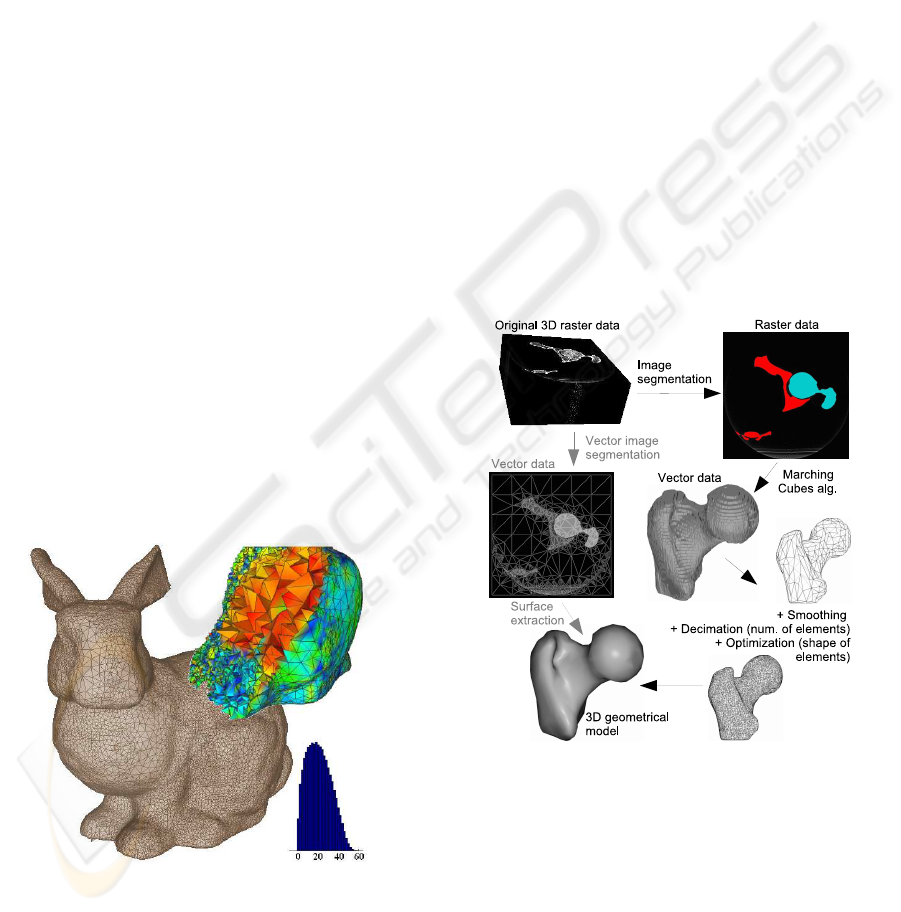
1 INTRODUCTION
Traditional raster-based segmentation methods pro-
duce data which are not suitable for geometrical 3D
modeling. Most often, an algorithm such as March-
ing Cubes (Lorensen and Cline, 1987) is applied to
reconstruct surfaces from the raster data. Therewith,
further decimation and smoothing of the model are
required.
Figure 1: Result of the proposed tetrahedral meshing
method, and histogram of the minimal dihedral angles in
the final mesh. The bunny was printed using rapid proto-
typing machine (3D printer) and scanned on a CT machine.
Afterwards, the volumetric data was processed.
Principal task of an image segmentation is the im-
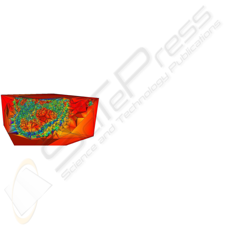
Figure 2: Comparison of the traditional raster-based seg-
mentation (black labeling) and the presented vector seg-
mentation method (gray).
age partitioning into a set of non-overlapping regions
so that variation of some property within each region
follows a simple model. It has been shown that 2D
Delaunay triangulation can be used to effectively par-
tition the image (Gevers, 2002), while the mesh is
adapted to the image structure by combining region
and edge information.
In this paper, recent advances in a vector segmen-
134
Spanel M., Krsek P., Svub M. and Stancl V. (2010).
VECTOR SEGMENTATION OF VOLUMETRIC IMAGE DATA - Tetrahedral Meshing Constrained by Image Edges.
In Proceedings of the International Conference on Computer Graphics Theory and Applications, pages 134-138
DOI: 10.5220/0002833201340138
Copyright
c
SciTePress

tation technique based on a 3D Delaunay Triangula-
tion are presented. This work follows principles pre-
viously described in (Spanel et al., 2007). Tetrahedral
mesh is used to partition volumetric image data into
regions (see Figure 2). Process of the mesh construc-
tion respects significant image edges, so surfaces of
image regions are well described and can be easily
derived.
2 TETRAHEDRAL MESHING
A mesh generation (George and Borouchaki, 1998)
aims at tessellation of a bounded 3D domain Ω with
tetrahedra. Algorithms for 3D mesh generation have
been intensively studied over the last years. Basi-
cally, three main families of algorithms have been de-
scribed: Octree methods, Advancing front methods,
and Delaunay-based methods (Owen, 1998).
2.1 Delaunay Triangulation (DT)
Every tetrahedron of the DT satisfies the Delaunay
criterion. This criterion means that circumsphere as-
sociated with the tetrahedron does not contain any
other vertices. This criterion is a characterization of
the Delaunay triangulation. The Delaunay triangula-
tion generates regularly shaped tetrahedra and is very
attractive from a robustness point of view due to sim-
plicity of the Delaunay criterion.
Constrained Delaunay triangulation (CDT) is a
triangulation where constraints given as set of edges
and faces in 3D remain as entities of the resulting
mesh. There are two classes of methods depending on
how the constraints must be satisfied. The first kind
acts by local modifications to enforce the given con-
straints, while the other kind tends to modify the con-
straints and creates an admissible set of constraints.
A Constraint partitioning method is a simple rep-
resentative of the second class. Every tetrahedron in-
tersected by a constrained edge/face is divided ensur-
ing that the created sub-edges are in the resulting tri-
angulation. Advantage of the constraint partitioning
method is that it can be easily extended to 3D.
Many Delaunay refinement methods (Shewchuk,
2002) exist that improve tetrahedra locally by insert-
ing new nodes to maintain the Delaunay criterion.
2.2 Isotropic Meshing
Many applications have specific requirements on the
size and shape of elements in the mesh. The aim of the
isotropic meshing is to locate vertices so that the re-
sulting mesh consists of almost equilateral tetrahedra.
In addition, the element size is close to a predefined
size constraint.
One of the existing methods to create vertices in
accordance with the size specifications, creation of
points along the edges, is discussed in (George and
Borouchaki, 1998). The idea is to create new points
along existing edges in the triangulation and obtain
nearly equilateral tetrahedra having edges of length h.
In (Spanel et al., 2007), this method has been modi-
fied for isotropic meshing of volumetric image data.
2.3 Variational Tetrahedral Meshing
Many approaches based on energy minimization (Du
and Wang, 2003) have been proposed as a powerful
tool in meshing. In this paper, a vector segmentation
technique, built upon a Variational Tetrahedral Mesh-
ing approach (Alliez et al., 2005), is presented. A
simple minimization procedure alternates two steps:
• Delaunay triangulation optimizing connectivity,
• local vertex relocation,
to consistently and efficiently minimize a global en-
ergy over the domain. It results in a robust meshing
technique that generates high quality meshes in terms
of radius ratios as well as angles.
To extend the approach to allow isotropic mesh-
ing, the sizing field H is introduced A mass density
in space can be defined and used in computation of
the optimal vertex position. This density should agree
with the sizing field. Alliez uses a one-point approxi-
mation of the sizing field in a tetrahedron. In geomet-
ric terms, an optimal position of the interior vertex X
i
in its 1-ring can be expressed as:
X
∗
i
=
1
∑
T
k
∈Ω
i
|T
k
|
h
3
(G
k
)
∑
T
j
∈Ω
i
|T
j
|
h
3
(G
j
)
c
j
. (1)
where G
k
is the centroid of tetrahedron T
k
.
In (Alliez et al., 2005), a default sizing field is
proposed, robust for a large spectrum of mesh types.
Definition of the sizing field is build on the notion of
local feature size that corresponds to the combination
of domain boundary curvature and thickness as well.
The local feature size l fs(P) at a point P of do-
main boundary is defined as the distance d(P, S(Ω))
to a medial axis S(Ω). The medial axis, or skeleton,
is the locus of all centers of maximal balls inscribed
in the boundary. Given the local feature size on the
boundary, we need a controllable way to extrapolate
this function to the interior. The function
h
P
= min
S∈δΩ
[Kd(P) + l fs(S)] (2)
satisfies this criterion. The parameter K controls gra-
dation of the resulting field.
VECTOR SEGMENTATION OF VOLUMETRIC IMAGE DATA Tetrahedral Meshing Constrained by Image Edges
135

3 DELAUNAY-BASED VECTOR
SEGMENTATION
Based on the introduced principles, the vector seg-
mentation was originally proposed as follows:
1. 3D edge and corner detection - Candidate vertices
lying on regions boundaries, meaningful edges
and corners are located.
2. Initial Delaunay triangulation - Tetrahedral mesh
is constructed from the sampled set of can-
didate vertices by the common Incremental
Method (George and Borouchaki, 1998).
3. Iterative adaptation - The triangulation is adapted
to the underlying image structure.
4. Mesh segmentation - Classification of tetrahedra
into image regions.
This paper introduces several changes in the orig-
inal segmentation. The mesh of the DT is adapted to
the image structure by means of isotropic edge split-
ting and variational meshing. The image is classified
into regions using a graph-based clustering algorithm.
3.1 3D Edge and Corner Detection
The triangulation starts with a set of candidate ver-
tices distributed over the entire image. In all our ex-
periments, the well known Canny edge detector ex-
tended to the 3D space has been used.
In order to respect significant features in the volu-
metric data during the meshing, we have modified the
Susan corner detector (Smith and Brady, 1996) ex-
tending its functionality into 3D space. The Susan
(Smallest Univalue Segment Assimilating Nucleus)
detector was originally developed to locate feature
points in 2D images.
Analogous to Smith and Brady, the modified 3D
SUSAN places a spherical mask R over the voxel to
be tested (the nucleus). The voxel in this mask is rep-
resented by v ∈ R. The nucleus is at v
0
. Every voxel is
compared to the nucleus using a distance function c
v
.
Final response of the SUSAN detector is proportional
to an area n(R) of the SUSAN given by:
n(R) =
1
N
∑
v
i
∈R
c
v
i
. (3)
In the equation (3), N is the number of voxels within
a spherical mask R used as a normalization factor. If
c
v
is the rectangular function, then the previously de-
fined area represents the number of voxels in the mask
having brightness similar to the nucleus.
Figure 3: Sampled initial set of vertices found by the edge
and corner detection.
3.2 Iterative Adaptation
Fundamental part of the proposed segmentation
method is adaptation of the mesh to cover the under-
lying image structure. Following two main steps are
repeated several times:
1. Isotropic edge splitting - creation of points along
existing edges, introduces new points to the mesh.
2. Variational meshing - optimization of the tessel-
lation grid by means of vertex moving.
Isotropic Edge Splitting. In this phase, the isotropic
meshing algorithm creating new points along existing
edges and another well known technique of tetrahe-
dral mesh optimization, splitting of maximal/longest
edge, are combined together. The splitting phase is
similar to the one described in (Spanel et al., 2007).
The only difference is definition of the sizing field, so
called control space.
The control space prescribes length of edges in
the mesh. In our case, control space enforces cre-
ation of larger tetrahedra inside image regions and
smaller ones along region boundaries (image edges).
Apparently, definition of the sizing field strongly af-
fects quality of the final mesh.
In this sense, one can define the control space
H(Ω) in the same way as the sizing field given by the
equation (2). This definition is robust and produces
high quality meshes. Instead of the conventional do-
main boundary, we define the control space to respect
found image edges. Thus, we generate the control
space differently:
1. Estimate distance transform from all detected im-
age edges first.
2. Find local maxima of the distance transform in or-
der to identify medial axis.
3. Evaluate local feature size l f s(P) on image
edges using inverse distance transform propagat-
ing value from the medial axis.
GRAPP 2010 - International Conference on Computer Graphics Theory and Applications
136
4. Generate control space distributing l f s(P) from
edges using the formula (2).
This sizing field is relative. It describes the
inhomogeneity of required edge length. The real
edge length is proportional to this relative value, and
depending on the prescribed number of vertices.
Variational Meshing. The variational meshing
phase, alternating connectivity and geometry opti-
mization, is an important part of the algorithm. The
energy is minimized by moving each interior vertex
to its optimal position. Further, the energy is mini-
mized by computing the 3D Delaunay triangulating
of these new sites.
Analogous to (Alliez et al., 2005), the boundary
vertices are treated differently. In order to identify
the current boundary vertices, each voxel V
i
lying on
an image edge is examined. Its nearest vertex S
j
in
the mesh is located, and the distance d(V
i
, S
j
) as well
as the coordinates of V
i
(multiplied by the distance
d) are accumulated at that vertex. To deal with cor-
ner points, the distance d is weighted according to
the point type. Corner points have the weight signifi-
cantly greater than edge points, thus the closest vertex
is attracted directly in place of the image corner.
Figure 4: Result of the adaptation of the mesh (K = 0.8).
Afterwards, all vertices with a non-zero distance
sum are the desired boundary vertices. These vertices
are moved to the average value they each have accu-
mulated during the pass over all edge voxels.
3.3 Mesh Segmentation
Every tetrahedron t
i
of the mesh is characterized by
its feature vector. Individual features detail image
structure of the tetrahedron and its close neighbour-
hood. In fact, the first two components are mean pixel
value and intensity variance of voxels inside the tetra-
hedron, other features may cover image texture.
Topology of the tetrahedral mesh is suitable for
graph-based segmentation techniques. Instead of pix-
els and the traditional 4– and 8– pixel connectedness,
tetrahedra and graph adjacency are incorporated.
Graph-based Segmentation. Viewing the mesh as
undirected graph, with edges weighted according to
similarity of feature vectors, allows one to use graph
algorithms (graph cuts, path algorithms, etc.) for the
segmentation.
In our experiments, we have used the Min-
Cut/Max-Flow algorithm proposed in (Boykov and
Kolmogorov, 2004) to cut a graph whose edges are
evaluated according to the similarity of two adjacent
tetrahedra.
4 RESULTS AND DISCUSSION
The proposed segmentation algorithm was tested on a
real CT imaging data (about 120− 150 slices, resolu-
tion 512x512 pixels per slice). The whole segmenta-
tion process, including iterative mesh adaptation and
final classification, takes approximately 15− 25 min-
utes on standard PC with Intel DualCore 2.54GHz
processor depending on concrete number of slices,
and parameters of the meshing algorithm.
Results of the segmentation shown in Figure 5
outperforms the original method (Spanel et al., 2007).
Especially, the overall mesh quality in the sense of
shape of tetrahedra has been improved. In the Fig-
ure 5, histograms show distribution of the minimal di-
hedral angles within regions of the tetrahedral mesh.
The graph-based mesh segmentation algorithm
designed for the unsupervised clustering of feature
vectors performs almost same, sometimes slightly
better, then the original method based on Fuzzy C-
means and GMM+EM clustering techniques. Further
improvement of the classification phase must incorpo-
rate more sophisticated image features modeling 3D
texture and spatial image properties.
An inconvenience of the described meshing tech-
nique is that slivers appear in the mesh, especially
close to the image edges. Regarding recent research
in this area, methods like the modified sliver exuda-
tion (Cheng et al., 1999), or sliver perturbation must
be incorporated in the meshing process in the future.
5 CONCLUSIONS
In this paper, the vector segmentation algorithm
based on isotropic Delaunay triangulation proposed
in (Spanel et al., 2007) is extended. To improve qual-
ity of the tetrahedral mesh, the variational meshing
is utilized. Instead of original clustering techniques,
the graph-cut algorithm is used to classify tetrahedra
VECTOR SEGMENTATION OF VOLUMETRIC IMAGE DATA Tetrahedral Meshing Constrained by Image Edges
137
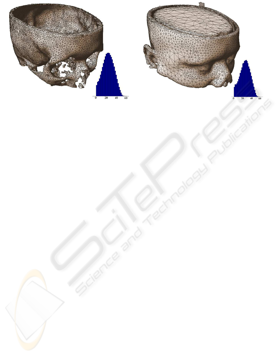
a) b)
Figure 5: Result of the vector segmentation. Polygonal surfaces of meaningful image regions were extracted directly from the
classified tetrahedral mesh: soft tissues (a), hard tissues (b).
into individual regions. Both modifications have im-
proved quality of the output mesh without significant
increase of runtime. Besides, there is still space for
improvement. It is necessary to deal with slivers, and
more sophisticated image features might be incorpo-
rated into the mesh classification.
In general, this concept of the volumetric im-
age segmentation has several advantages. Tetrahe-
dral representation of image regions provides con-
tinuous approximation of region boundaries (image
edges), while the process of raster data vectorization
is eliminated. Moreover, a more effective representa-
tion of the image structure is obtained. Mesh structure
decreases complexity of any classification algorithm
that processes a reduced number of tetrahedra instead
of voxels.
ACKNOWLEDGEMENTS
The authors were supported by the Faculty of
Information Technology, BUT under project no.
MSM0021630528 CZ, and CESNET association un-
der project no. MSM6383917201 CZ.
REFERENCES
Alliez, P., Cohen-Steiner, D., Yvinec, M., and Desbrun, M.
(2005). Variantional tetrahedral meshing. ACM Trans.
Graph., 24(3):617–625.
Boykov, Y. and Kolmogorov, V. (2004). An experimental
comparison of min-cut/max-flow algorithms for en-
ergy minimization in vision. In IEEE Transactions
on PAMI, 26(9):1124–1137.
Cheng, S. W., Dey, T. K., Edelsbrunner, H., Facello, M. A.,
and Teng, S. H. (1999). Sliver exudation. In In Proc.
15th ACM Symp. Comput. Geom., pages 1–13.
Du, G. and Wang, D. (2003). Tetrahedral mesh generation
and optimization based on centroidal voronoi tessella-
tions. Inter. Journal on Numerical Methods in Engi-
neering, 56(9):1355–1373.
George, P. L. and Borouchaki, H. (1998). Delaunay Tri-
angulation and Meshing: Application to Finite Ele-
ments. Editions HERMES, Paris, France.
Gevers, T. (2002). Adaptive image segmentation by com-
bining photometric invariant region and edge informa-
tion. In IEEE Trans. on Pattern Analysis and Machine
Intelligence, volume 24.
Lorensen, W. E. and Cline, H. E. (1987). Marching cubes:
A high resolution 3d surface construction algorithm.
In SIGGRAPH’87, volume 21, Anaheim. Computer
Graphics.
Owen, S. (1998). A survey of unstructured mesh genera-
tion technology. In Proceedings of the Seventh Inter-
national Meshing Roundtable, Dearborn, Michigan.
Sandia National Laboratories.
Shewchuk, J. R. (2002). Delaunay refinement algorithms
for triangular mesh generation. Computational Ge-
ometry: Theory and Applications, 22:21–74.
Smith, S. M. and Brady, J. M. (1996). Susan - a new ap-
proach to low level image processing. Inter. Journal
of Computer Vision.
Spanel, M., Krsek, P., Svub, M., Stancl, V., and Siler, O.
(2007). Delaunay-based vector segmentation of vol-
umetric medical images. In In Proc. of CAIP 2007,
pages 261–269. LNCS 4673.
GRAPP 2010 - International Conference on Computer Graphics Theory and Applications
138
