
IMPLEMENTATION ANALYSIS FOR A HYBRID PARTICLE
FILTER ON AN FPGA BASED SMART CAMERA
I. Zuriarrain, N. Arana
Signal Processing and Communications Group, University of Mondragon, Loramendi 4, Mondragon, Spain
F. Lerasle
Groupe Robotique, Action et Perception, Laboratoire d’Analyse et d’Architecture des Systemes, Toulouse, France
Keywords:
Multitarget tracking, SystemC, Smart camera, Field programmable gate arrays, Transaction level modeling.
Abstract:
Design and development of embedded devices which perform computer vision related task presents many
challenges, many of which stem from attempting to ?t the complexity of many higher level vision algorithms
into the constraints presented by programmable embedded devices. In this paper, we follow a simulation-
based methodology in order to develop an architecture which will allow us to implement a mixed Particle
Filter/Markov Chain Monte Carlo tracking algorithm in an FPGA-based smart camera, using tools such as
SystemC and Transaction LevelModeling (TLM). Use of these tools has allowed us to make some preliminary
predictions as to the memory usage and performance of the system, which will be compared to the results of
more detailed simulations obtained in the way towards implementing this system.
1 INTRODUCTION
Implementing any sort of complex vision algorithm
within the restrictions imposed by use of an embed-
ded platform is not a trivial task. There are many
challenges that stem both from the limited resources
(processing time, memory, power), and from unde-
fined architectures (when compared, for example, to
a desktop computer, where the architecture is both
well-known and standard). Deciding which architec-
ture suits a particular algorithm the best is often, in
itself, a challenge.
With that in mind, simulation turns out to be an
invaluable tool. It allows the developers to coalesce
the known data (e.g., functional characteristics of the
algorithm, quality restrictions, physical limits of the
platform) of the different elements that compose the
system, and explore and analyze different architec-
tures that might fit the problem at a fraction of the
cost of actual implementation.
In Zuriarrain et al. (2008) a hybrid Particle Fil-
tering/Markov Chain Monte Carlo algorithm was pro-
posed that performs the detection and tracking of mul-
tiple humans in an indoors environment, which was
developed using a PC. In this paper, we take that al-
gorithm as a base and present a design for its imple-
mentation in an FPGA based smart camera, following
a simulation-based methodology.
This methodology intends to take advantage of the
resources that simulation provides us in order to de-
tect conflict areas in the implementation early on (e.g.,
does the algorithm require more memory than the sys-
tem can provide?), as well as develop an architecture
for the implementation of said algorithm within the
limits imposed by the hardware platform. We will
present some results from the preliminary simulation,
and compare them to results obtained from simula-
tions that are more detailed (by virtue of being closer
to being an RTL implementation of the algorithm) for
a subset of the architecture, in order to establish the
reliability of the original data.
First, in Section 2 we will explain the smart cam-
era architecture we are working with. Then, in Sec-
tion 3 we will explain the hybrid tracking algorithm
and its structure. In Section 4 we will take a look at
the methodology used to arrive to a working model of
the hardware system. In Section 5 we will discuss the
experimental results derived from the simulations and
the accuracy of said results, by comparing them with
the results of the simulation of a more detailed model.
Finally, we will close with the conclusions and a few
comments on future works.
174
Zuriarrain I., Arana N. and Lerasle F. (2010).
IMPLEMENTATION ANALYSIS FOR A HYBRID PARTICLE FILTER ON AN FPGA BASED SMART CAMERA.
In Proceedings of the International Conference on Computer Vision Theory and Applications, pages 174-179
DOI: 10.5220/0002834101740179
Copyright
c
SciTePress
2 THE SMART CAMERA
PLATFORM
The field of smart cameras has become very popu-
lar thanks to its advantages in scalability, both in pro-
cessing power (since an important part of the process-
ing is done by each sensor, there is no need for an
overly powerful central station) and network perfor-
mance (as the cameras can transmit only the informa-
tion they extract from the images, and avoid actually
transmitting video until it becomes necessary). This
has led to the development of a number of approaches
to smart camera development, as we are going to de-
scribe in the next paragraphs.
The integration of a microprocessor (whether an
embedded one, or the more powerful desktop proces-
sors) within the camera is perhaps the most intuitive
form of developing a smart camera, and there are cur-
rent off-the-shelf comercial smart cameras that fol-
low this design (Bramberger et al., 2004). However,
most common microprocessors have very limited par-
allelization options, being mainly sequential, and do
not take advantage of the parallelization possibilities
of many low level image processing algorithms.
A variation on this theme is to use a SIMD (Sin-
gle Instruction Multiple Data) processor. SIMDs are
basically an array of simple processors, which can ex-
ecute the same operation on multiple pieces of data at
the same time (Kleihorst et al., 2004). This allows the
system to operate on multiple pixels in parallel, mak-
ing it very well suited for low-level image processing,
and other cases in which we need to process multiple
pieces of completely independent data.
Another possibility for smart camera design is
based on reconfigurable hardware, such as FPGAs
(Leeser et al., 2004). This enables a great amount
of flexibility, since the device can be programmed to
best suit our architecture, as well as offering posi-
bilities for online reconfiguration(Dias et al., 2007).
However, FPGAs are best used in processing paral-
lel algorithms, as they are not quite as well suited to
sequential algorithms as classic microprocessors.
There is nothing constraining a design to using
only one of these approaches, and various hybrid ap-
proaches have been developed that integrate an ele-
ment well suited for parallel processing with an em-
bedded processor or a DSP for the sequential process-
ing, such as the camera used by Fleck et al (Fleck et
al., 2007).
Since particle filtering is a popular approach for
human tracking, there have been previous efforts to
implement particle filters in FPGA based devices.
Hong et al. (2004) utilize block level pipelining
and dataflow structure transformations in order to im-
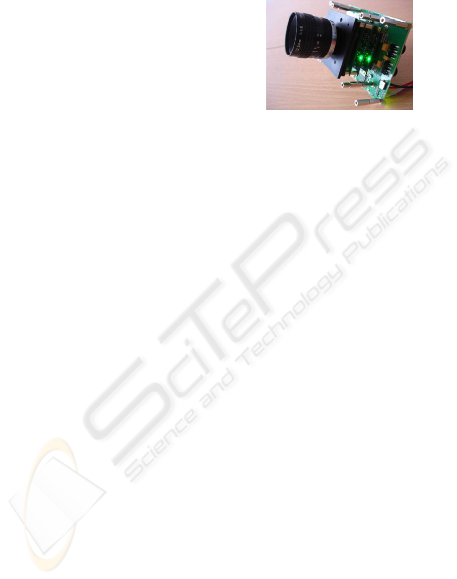
Figure 1: DTSO smart camera.
plement different kinds of particle filters, taking ad-
vantage of common blocks in the different particle fil-
ter variants. However, so far this methodology has not
been extended to multiple target tracking and is not
particularly oriented towards vision-based tracking.
In this vein, but oriented towards human tracking,
we can find the work of Cho et al. (2006), who im-
plement a grayscale particle filter in an FPGA. The
main differences with our work are three: first, the
algorithm is different, since we use a hybrid particle
filter, also making use of colour cues while they work
in grayscale; also, in our case, the FPGA module is
integrated in the camera, while Cho et al. keep it sep-
arate, which makes the communication with the cam-
era more complex; third, no mention is made of which
methodology Cho et al. followed in their work. In our
case, the methodology is explicitly explained in Sec-
tion 4.
The camera we have selected to work with is
an FPGA based smart camera (Figure 1) by Delta
Technologies Sud Ouest (DTSO), a company from
Toulouse, France. DTSO has taken part in the project
that has resulted in this research, and they have
also been collaborators in earlier computer vision
projects(Fillatreau et al., 2009).
The DTSO iCam camera is currently fitted with
two FPGA modules. Each of these modules is based
on an Altera Cyclone-II FPGA, and includes a 18
megabit memory module (with 18 bit words), as well
as the communications with the neighbouring mod-
ules. Currently, all programming of the FPGA mod-
ules must be done using the JTAG cable while the
camera is out of its enclosure, so there is no means
for online reconfiguration.
Communications between the camera and other
external devices is currently done using wither an
Ethernet communications module or a Wi-Fi module,
since the camera is intended not as a stand-alone prod-
uct, but as a member of a network of cameras. This
also allows for some of the processing to be done in
a more conventional processor, since the communica-
tions module includes a Freescale processor.
IMPLEMENTATION ANALYSIS FOR A HYBRID PARTICLE FILTER ON AN FPGA BASED SMART CAMERA
175
The first version of the camera could only take im-
ages in greyscale, but it has been extended for colour
image capture as well. The colour sensor of our smart
camera captures images in a bayer mosaic format, so
a part of the first FPGA module has been dedicated to
a debayering block, using a simple value average for
neighbouring pixels.
3 THE MIXED MCMC/PF
TRACKING ALGORITHM
In Zuriarrain et al. (2008), a mixed Markov Chain
Monte Carlo/Particle Filtering algorithm was pro-
posed in order to track a variable number of people
in an indoors scene. An overview of the algorithm
follows, though with implementation details mostly
omitted.
The principle of the tracker is depicted in algo-
rithm (1). It is based on the original ICONDENSA-
TION framework (Isard and Black, 1998) which has
nice properties for sampling thanks to both visual de-
tectors and target dynamics.
Algorithm 1: Hybrid MCMC/PF algorithm at
frame k.
1: Generate detection saliency maps
2: Generate dynamic model saliency map
3: Generate unified saliency map S
4: for i = 0 to N
p
do
5: repeat
6: Draw position for particle x
i
k
7: Draw threshold α
r
8: until S(x
i
k
) > α
r
9: for j = 0 to N
i
do
10: Draw new state x
0
and threshold α
m
11: Evaluate proposal probability for x
0
12: if Proposal probability ≥ α
m
then
13: x
i
k
= x
0
14: else
15: x
i
k
= x
i
k
16: end if
17: end for
18: end for
19: Calculate particle weights
20: Calculate MAP estimator
The importance function for this algorithm is
based on saliency maps which encode information
about target dynamics and visual detectors. These
maps are then merged (step 3) in a single saliency
map that shows all high probability areas for particle
placement. All these saliency maps (except for the fi-
nal merged map, for obvious reasons) are completely
independent and so can be computed in parallel.
The particle sampling is done using a process
of rejection sampling (step 5). This combination of
saliency maps and rejection sampling ensures that the
particles will be placed in the relevant areas of the
state space.
The process so far assumes the number and identi-
ties of the targets remain constant. In order to manage
such discrete variables, a Markov chain is used(step
9). In this step, changes to the configuration of the
target set are proposed for each particle, which are
accepted or rejected based on their proposal probabil-
ities. Traditionally, a MCMC process requires a high
number of burn-in iterations. In this case, the itera-
tion number N
i
can be reduced drastically as: (1) the
particle set introduces diversity in the jump dynamics,
(2) the continuous parameters are handled by the im-
portance sampling. Given the particles sampled in the
previous step, the initial state configuration is usually
close to the final one.
In the weighting phase (step 19), the likelihood
of each particle is measured and a weight is assigned
to each particle. These measurements are detailed in
(Zuriarrain et al., 2008), but in general suffice to say
that both colour and motion cues are used.
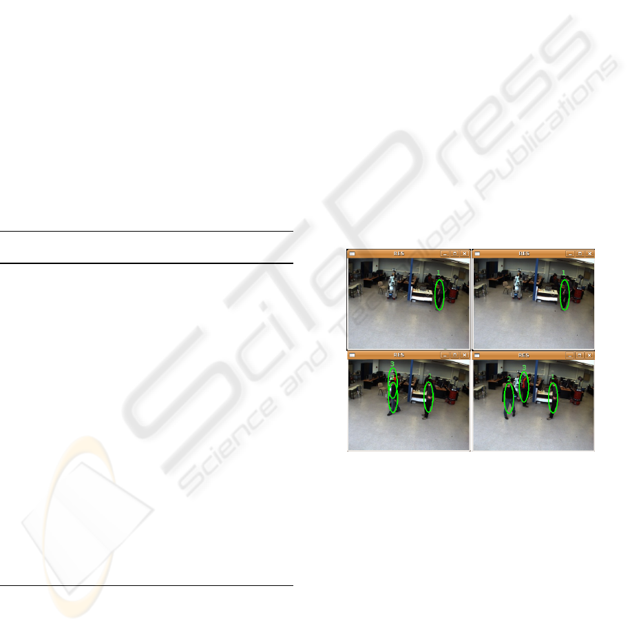
Figure 2: Snapshots of a test sequence involving three peo-
ple.
Finally, the most probable state vector is selected
from between the particles (step 20).
In a 2.4GHz Pentium IV computer, this algorithm
ran unoptimized at around 1 fps. While this is not
fast enough for real time video monitoring efforts, and
would certainly slow even further if more process-
ing was added (e.g., for pose and activity interpreta-
tion), simulations show that performance is much im-
proved when implemented in an FPGA-based device
(as shown in section 5).
The architecture of the software model for the
above algorithm can be divided in two phases: de-
tection and tracking. In the detection phase, we run
VISAPP 2010 - International Conference on Computer Vision Theory and Applications
176
all the detectors for a given image, generating the
saliency map. Then, in the tracking phase, we draw
the particles based on that saliency map, and then a
short MCMC process is applied to predict changes in
the number of targets.
4 SYSTEMC AND TLM
MODELING
Implementing any non-trivial algorithm in hardware
is in itself a non-trivial problem that requires both a
good knowledge of low level design and program-
ming techinques, and a very intimate knowledge of
the target algorithm. Even then, there are a number of
design decision that might have unforeseen effects on
the final implementation.
In order to lessen the effect of these factors, a
working model of how the algorithm will behave
when implemented in a certain manner is an invalu-
able tool, in that it allows us to test the outcome of
changes performed to the implementation in a frac-
tion of the time and cost it would take to actually im-
plement and test it, as well as giving us a clear idea
of what the non-functional parameters of the process
(such as execution speed or reliability) will be. Also,
for those cases where the system has both a hardware
and a software component, having a clear model al-
lows for easier and more efficient partitioning (Jin and
Sin-Chong, 2006).
In this context, we can find efforts such as the
Hardware Resource Model promoted by the Object
Management Group (Taha et al., 2007), which of-
fers a framework in which the developers may de-
scribe a model of the hardware. This model is part
of a bigger framework for the modeling of real time
systems named MARTE (Modeling and Analysis of
Real-Time and Embedded systems). On the other
hand, there are also a variety of languages oriented
towards codification of the model in a high level lan-
guage, such as HandelC or SystemC.
SystemC has been used in a number of works,
such as Gerin et al. (2006), Jin et al. (2006), Helm-
stetter et al. (2008) and Amer et al. (2005), perhaps as
a result of the introduction of TLM (Transaction Level
Modeling). The basis behind TLM is that, when mod-
eling a hardware system, having models at different
abstraction levels enables the developer to maintain a
working model at all times during the development of
the system, from the functional model down to a cycle
accurate RTL model. A common classification of the
different abstraction levels for these models is shown
in Table 1.
In order to arrive to a working model of the al-
Table 1: Detail levels of Transaction-Level Models(Black
and Donovan, 2004).
Model Communication Functionality
SAM Untimed Untimed
Component Assembly Untimed Approximated
Bus Arbitration Approximated Approximated
Bus Functional Cycle Accurate Approximated
Cycle Accurate Computation Approximated Cycle Accurate
RTL Cycle Accurate Cycle Accurate
gorithm explained in Section 3, we have followed an
iterative methodology based on SystemC and TLM.
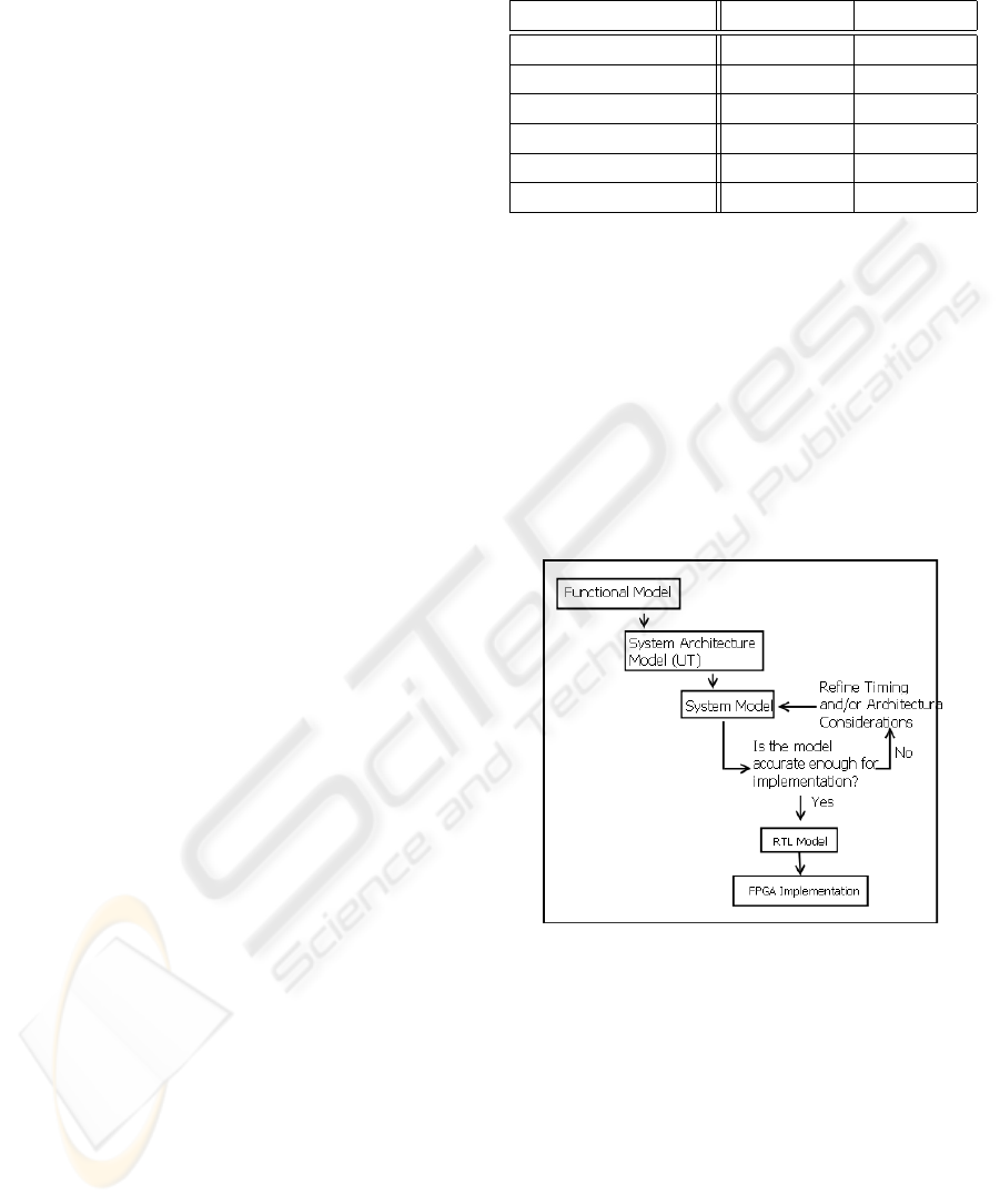
The workflow for the methodology we have used
is shown in 3, and follows a common iterative pat-
tern. The model starts as a functional model with no
information of how the system is going to be imple-
mented (i.e., a C++ implementation of the algorithm),
and goes through several iterations of increasingly de-
tailed analysis, with each of these iterations produc-
ing a new model with greater implementation infor-
mation.
Figure 3: Simplified workflow for the implementation of an
algorithm in hardware using TLM.
In our case, we have started with the Functional
Model, which has been refined into a System Archi-
tecture model by iterative partitioning of the different
subsystems: at the highest levels, the whole system is
comprised of a single block, which allows us to model
input and output to the whole system. Further refining
shows the major blocks of the algorithm, until finally,
the end architecture somewhat mirrors the original al-
gorithm, as shown in Figure 4.
A similar process is followed when adding timing
information to the different parts of the design, in that
we begin with general timing information (e.g., ”the
system takes 9.6 milliseconds to receive a frame”) and
IMPLEMENTATION ANALYSIS FOR A HYBRID PARTICLE FILTER ON AN FPGA BASED SMART CAMERA
177

Figure 4: Architecture of the tracking algorithm hardware
after refinement with the simulation.
keep adding detail as we move to lower level models.
Obviously, the initial prediction is not perfectly accu-
rate except in trivial cases, being a global generaliza-
tion, but as we refine the model and start adding tim-
ing information to more precise operations (e.g., the
transmission of a single pixel, as opposed to the whole
image), the accuracy of the predictions increases.
5 SIMULATION RESULTS
According to the simulation, the algorithm has a max-
imum runtime of 55 ms (approximation made by as-
suming the most pessimistic case for all processes
with a variable number of iterations), which would al-
low it to run at slightly better than 18 fps. Further op-
timisation of the design (e.g., by using multiple parti-
cle processing modules, introducing pipelining at cer-
tain points of the particle probability calculation, and
using the data generated in previous calculations of
the histogram to reduce the number of necessary op-
erations) is still possible, and would be desirable in
order to allow for the ampliation of the functionality
of the tracker.
Although initially it was believed that the camera
(with the current amount of FPGA modules) would
not be able to run this particular algorithm due to an
insufficient amount of onboard memory, simulations
have shown that assumption to be incorrect. The cam-
era has one 18 mbit memory chip per FPGA board,
totalling 36 mbits of internal memory. According to
the simulation, operation of the algorithm can be done
in 31.5 mbits, which would put it well inside the ca-
pabilities of the camera.
The main obstacle to implementation of the al-
gorithm in the selected smart camera is that the cur-
rent communication modules for connecting the dif-
ferent FPGA boards were designed to allow for uni-
directional communication. The feedback loop in the
particle filtering algorithm that allows the system to
calculate the dynamic model for the targets becomes,
then, very inconvenient, since it means a redesign of
the communication modules would be necessary in
order to implement the full algorithm in the camera.
In order to establish the validity and accuracy of
these results, a component of the algorithm has been
taken further along the model chain than the rest of the
model. The component chosen was the background
subtraction module, which we believe has enough
complexity to be a representative sample of the algo-
rithm, while still being simple enough that the imple-
mentation effort would not be overly demanding.
The detailed hardware architecture model for this
component can be seen in Figure 5. It is divided
in three areas, corresponding to reception of images
(left), background subtraction (middle) and connected
components clustering (right).
The results of this new model are threefold: first,
it has become clear that an assumption in an ear-
lier model (that there would be no memory conflicts)
doesn’t hold, and so there are a number of waiting
times that need to be taken into account that were ig-
nored in earlier models. While this doesn’t really af-
fect the runtime, since this section of the algorithm
still runs faster than it receives data, it does imply
that other sections of the model might be likewise
affected. Second, the connected component cluster-
ing part of the system would perform better in a se-
quential processor, as opposed to an FPGA, due to its
Figure 5: Detailed HW architecture model for the Back-
ground Subtraction component.
VISAPP 2010 - International Conference on Computer Vision Theory and Applications
178

inherently sequential nature. Third, the memory re-
quirements of the system were correctly modeled in
the original model, so the camera should still be able
to run the algorithm with the available memory (once
the feedback communication problem is solved).
6 CONCLUSIONS
Computer vision is an area where implementation in
hardware is highly beneficial, due to the parallel na-
ture of many vision algorithms. However, this is not a
trivial task, and a variety of methodologies and tools
have been used during the years in order to limit the
amount of effort necessary.
In this paper, we have presented the results of a
simulation model for a hybrid particle filter/markov
chain monte carlo algorithm to be implemented in
an FPGA-based smart camera. This model was
built using the SystemC modeling language and TLM
methodologies, which help reduce the amount of
work necessary before having concrete results.
These results show that the camera will need some
modifications to be able to run the algorithm, due
to some design constraints and the amount of mem-
ory available in each FPGA module, but also show a
marked improvement in execution performance when
compared to the same algorithm running in a PC (18
fps in the simulation vs 1 fps in the PC).
In more general terms, the results confirm that
simulation, even from an early level in the develop-
ment, can provide us with information that can help
make informed decisions w.r.t. system architecture
and capabilities at a fraction of the effort necessary
for actual implementation in a HDL language.
REFERENCES
I. Amer, M. Sayed, W. Badawy and G. Jullien, (2005)
”On the way to an H.264 HW/SW reference model:
A SystemC modeling strategy to integrate selected
IP-blocks with the H.264 software reference model”,
IEEE Workshop on Signal Processing Systems, SiPS:
Design and Implementation, Athens, Greece.
D. C. Black and J. Donovan, (2004) ”SystemC: From the
Ground up”, Springer.
M. Bramberger, J. Brunner, B. Rinner, and H. Schwabach,
(2004) ”Real-time video analysis on an embedded
smart camera for traffic surveillance” in Proc. RTAS
2004, pp. 174-181.
Jung Uk Cho, Seung Hun Jin, Xuan Dai Pham, and Jae
Wook Jeon, (2006) ”Object Tracking Circuit using
Particle Filter with Multiple Features”, SICE-ICASE.
F. Dias, F. Berry, J. Serot, and F. Marmoiton, (2007) ”Hard-
ware, design and implementation issues on a FPGA-
based smart camera”, First ACM/IEEE International
Conference on Distributed Smart Cameras, Vienna,
Austria.
S. Fleck, F. Busch, and W. Straßer, (Jan. 2007) ”Adap-
tive Probabilistic Tracking Embedded in Smart Cam-
eras for Distributed Surveillance in a 3D Model” in
EURASIP Jounal on Embedded Systems, vol. 2007.
P. Fillatreau, N. Arana, E. Saenz de Argandoa, A. Izagirre,
I. Zuriarrain, and R. Pop, (2009) ”An Industrial Val-
idation of Artificial Vision Techniques for the Con-
trol of Future High Speed Forming Processes”, Flex-
ible Automation & Intelligent Manufacturing, Mid-
dlesbrough, UK.
P. Gerin, Shen Hao, A. Chureau, A. Bouchhima, and
A. Jerraya, (2007) ”Flexible and executable hard-
ware/software interface modeling for multiprocessor
SoC design using SystemC”, Asia and South Pacific
Design Automation Conference, Yokohama, Japan.
C. Helmstetter and V. Joloboff, (2008) ”SimSoC: a Sys-
temC TLM integrated ISS for full system simulation”,
IEEE Asia Pacific Conference on Circuits and Sys-
tems, Macao, China.
S. Hong, X. Liang, and P.M. Djuric, (2004) ”Reconfig-
urable particle filter design using dataflow structure
translation”, IEEE Workshop on Signal Processing
Systems, Austin, TX, USA.
M. Isard and A. Blake, (1998) ”ICONDENSATION: Uni-
fying low-level and high-level tracking in a stochastic
framework” in European Conf. on Computer Vision,
London, UK.
Lee Jin and Park Sin-Chong, (2006) ”Transaction
level modeling for hardware architecture exploration
with IEEE 802.11n receiver example”, International
Conference on Communication Technology, Guilin,
China.
R. Kleihorst, M. Reuvers, B. Krose, and H. Broers, (2004)
”A smart camera for face recognition”, Internation
Conference on Image Processing, Singapore.
M. Leeser, S. Miller, and Yu Haiqian, (2004) ”Smart cam-
era based on reconfigurable hardware enables diverse
real-time applications” in Proc. 12th Annual IEEE
Symposium on Field-Programmable Custom Comput-
ing Machines, pp. 147-155.
S. Taha, A. Radermacher, S. Gerard, and J.-L. Dekeyser,
(2007) ”An open framework for detailed hardware
modeling” in Proc. 2007 Symposium on Industrial
Embedded Systems, pp. 118-125.
I. Zuriarrain, F. Lerasle, N. Arana, and M. Devy, (2008)
”An MCMC-based Particle Filter for Multiple Per-
son Tracking”, International Conference on Pattern
Recognition, Tampa, FL, USA.
IMPLEMENTATION ANALYSIS FOR A HYBRID PARTICLE FILTER ON AN FPGA BASED SMART CAMERA
179
