
XFEM FRAMEWORK FOR CUTTING SOFT TISSUE
Including Topological Changes in a Surgery Simulation
Luis F. Guti
´
errez and F
´
elix Ramos
Department of Computer Science, CINVESTAV-Guadalajara, Av. Cient
´
ıfica 1145, Zapopan, Jalisco, 45015, Mexico
Keywords:
XFEM, Cutting soft tissue, Surgery simulation.
Abstract:
Currently, there are many approaches in computer graphics (CG) that deal with topological changes; some of
these are non-interactive animations, unstable or not precise enough to medical applications. It has been found
that the Extended Finite Element Method (XFEM) is stable, accurate, with excellent performance and suitable
for virtual surgery in real time; nevertheless, to maintain the provided advantages, the selection and creation of
a set of CG methods is required that fulfill the requirements of the XFEM. We propose an embedded mapping
method that enables the relation of the XFEM elements, with the visual and collision meshes, making the user
interaction more dynamic. Furthermore, based on this new mapping method an interactive cutting algorithm is
suggested considering a geometric analysis. The XFEM, as a core of our framework, efficiently simulates the
topological changes consequently, making the interaction in real time possible, which will allow the creation
of more complex simulations of higher impact in the medical area.
1 INTRODUCTION
From the perspective of computer graphics in
medicine, the computer can allow surgeons or med-
ical students to analyze patients before performing
the surgery by simulating the physical behavior of the
body, giving the possibility to train the procedures,
avoiding the risks caused to patients by the lack of
experience. In order to simulate the incisions in a
realistic manner, the physical based methods are re-
quired, these give the adequate accuracy; Neverthe-
less, an interactive and real time simulation is desir-
able; therefore, it is necessary to look for efficiency in
the methods and the stability in the simulation. De-
spite many approaches deal with topological changes,
these do not fulfill the necessary characteristics previ-
ously described.
We identify the XFEM as a method that ensures a
robust simulation; however, there is no framework to
exploit its benefits to make it applicable to complex
simulations as surgery simulation. Hence, it is neces-
sary to design a framework completely focused on the
XFEM in order to obtain efficient responses.
This paper explains how to introduce the XFEM
in a surgery simulation including a geometric analysis
of our cutting method considering how this affects the
collision algorithm, mapping method and the remesh-
ing process. Moreover, many other aspects have been
considered in order to achieve a real time simulation
such as haptic interaction, handling multiple topolo-
gies, etc.
There are many researches that work with soft tis-
sue deformation without changing the topology, how-
ever, the majority of surgery procedures require inci-
sions and dissections; thus, this paper aims to provide
a framework that is easy to implement and suitable
for an interactive virtual surgery simulation including
topological changes.
This paper is organized as follows: a review of the
related work is analyzed in Section 2. After, in Sec-
tion 3 the design of our framework is explained based
on the XFEM and the embedded mapping method
that works as mediator between the physical origi-
nal mesh and the other meshes (visual and collision),
also the creation of a specific cutting algorithm that
quickly updates the associations of the meshes. Fur-
thermore, the implementation and testing employing
SOFA framework in 2D and 3D is showed in Section
4. Finally, in Section 5 the main contributions of our
framework are emphasized; moreover, the limitations
and the future work are also mentioned.
275
Gutiérrez L. and Ramos F. (2010).
XFEM FRAMEWORK FOR CUTTING SOFT TISSUE - Including Topological Changes in a Surgery Simulation.
In Proceedings of the International Conference on Computer Graphics Theory and Applications, pages 275-283
DOI: 10.5220/0002836402750283
Copyright
c
SciTePress
2 CUTTING APPROACHES
The majority of the applications oriented to medicine,
model the tissue using physically-based methods (Vi-
dal et al., 2006); the most popular is the FEM because
of its accuracy on the results. An overview of phys-
ically based models and applications can be found in
(Nealen et al., 2005).
Complex medical simulations require topological
changes; but, this is a challenging work to simulate in
real time with enough accuracy.
A surgery simulation must show the split of the
elements according to the cutting trajectory. A simple
manner to cut a tetrahedron is subdividing it into more
small sub-tetrahedrons (Bielser et al., 2003). Nev-
ertheless, subdividing can cause simulation instabil-
ity because it generates ill-conditioned elements (sliv-
ers); moreover, the subdivision increments the de-
grees of freedom (DOFs) impacting directly on the
simulation performance. Another alternative con-
sists of removing the elements in contact with the
blade (Forest et al., 2005); despite this method has
the advantage that it does not affect the simulation
stability, it is physically inaccurate and visually un-
even; another option, to avoid the previous meth-
ods, is a successive snapping of nodes to the cut-
ting trajectory (Serby et al., 2001); unfortunately,
this kind of method leads to degenerated elements.
Other approaches merge methods like snapping and
subdivision (Steinemann et al., 2006), but only non-
progressive cutting is enabled.
For fractures simulation, the virtual node algo-
rithm is proposed (Molino et al., 2004); it consists
of replicating cut elements assigning a portion of ma-
terial to each copy, it maintains the initial FEM mesh
conditioning, creating a minimal number of elements;
however, the slivers are not completely avoided; the
limitations of the virtual node algorithm were re-
solved by (Sifakis et al., 2007), avoiding slivers and
allowing arbitrary cutting of tetrahedrons in any num-
ber of sub-elements; nonetheless, both previous ap-
proaches have been tested in an offline simulation
which is undesirable for a surgery simulation.
(Je
ˇ
r
´
abkov
´
a and Kuhlen, 2009) employ the XFEM
to physically control the mesh when a cut appears,
while the user is cutting no new elements are cre-
ated (in the original mesh); thus the simulation perfor-
mance is not greatly impacted moreover, the XFEM
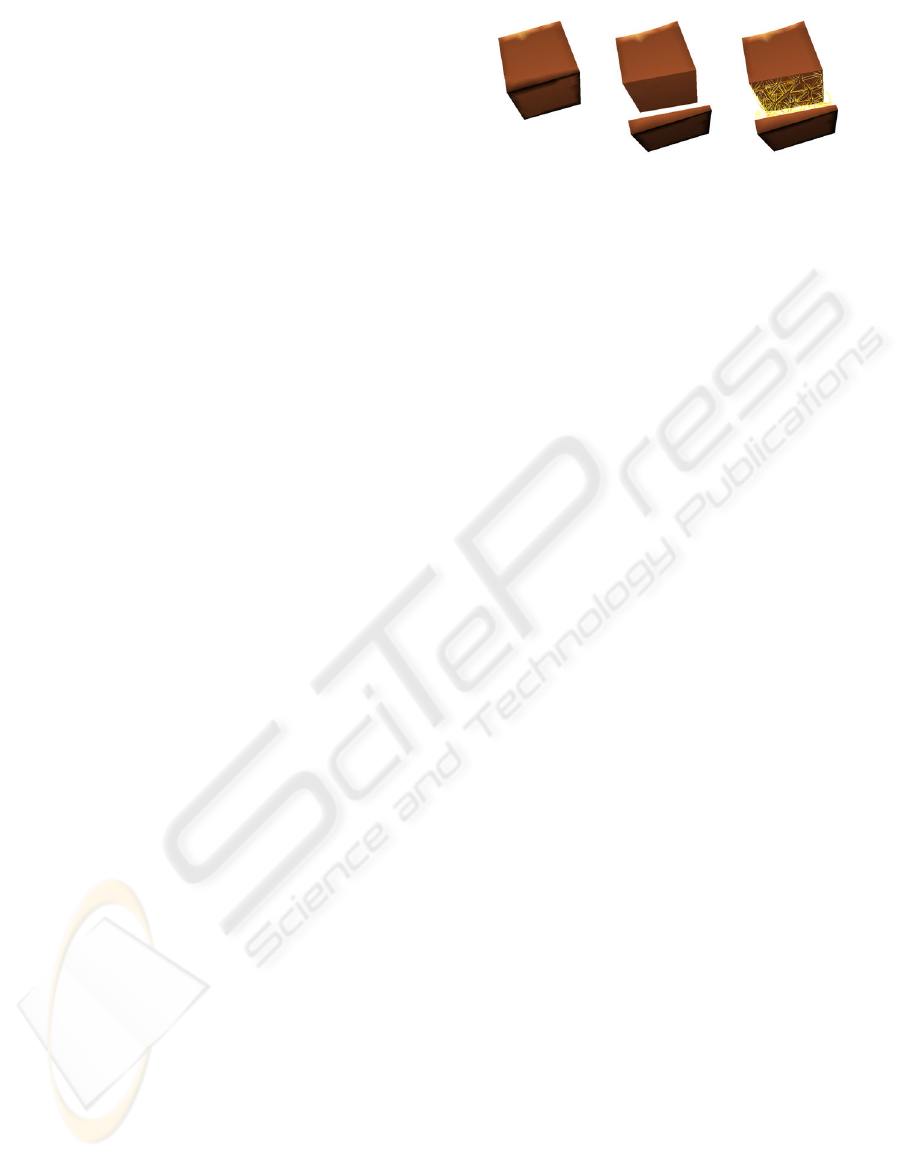
avoids ill-conditioned elements. Figure 2 shows how
the XFEM allows the simulation of the discontinuities
maintaining the original mesh.
The XFEM adds local enrichment functions in
sub-regions with discontinuities; this method, pro-
posed in 1999 by (Belytschko and Black, 1999), ex-
Figure 1: The alternative mesh helps to map the visual el-
ements with its corresponding physical elements, this mesh
is displayed on the right side.
ploits the partition of unity property of finite elements
(Babuska and Melenk, 1997). The XFEM was ini-
tially utilized for fracture mechanics to simulate the
crack growth with stiff materials, this method has
been improved and can be applied to different do-
mains such as material interfaces, 3D elasto-plastic
deformations, fluid mechanics, material-nonmaterial
interfaces and topology optimization considering void
spaces (Nesme et al., 2009). We explain the basics of
the XFEM in the appendix.
The XFEM was introduced to simulation of sur-
gical cuts by (Vigneron et al., 2004), implementing
a simulation of 2D MRI image with small defor-
mations. (Linblad and Turkiyyah, 2007) propose a
framework based on the FEM considering predefined
boundaries for cutting and suturing; to cut arbitrary
surfaces they employ the XFEM; this approach also
allows small deformation as a linear discontinuous
FEM was used. Later, (Turkiyyah et al., 2009) de-
scribe an algorithm for cutting using discontinuous
FEM considering large deformations; nevertheless,
this approach is described considering only the sur-
face triangular mesh.
3 XFEM FRAMEWORK
The fundamentals of the XFEM are described by
(Je
ˇ
r
´
abkov
´
a and Kuhlen, 2009), they use the XFEM
leading into a stable and accurate simulation. Never-
theless, their approach is very general, omitting how
the XFEM must interact with other methods of CG
without losing its advantages. Thus, our objective is
to create a specific framework that exploits the ad-
vantages of the XFEM and, by setting the XFEM as a
core of the simulation, create more complex surgery
simulations which we know will be stable, accurate
and interactive in real-time.
3.1 Corotational XFEM
The co-rotational FEM has been used for some ap-
proaches such as (M
¨
uller and Gross, 2004), show-
ing that it is physically accurate and suitable for real-
GRAPP 2010 - International Conference on Computer Graphics Theory and Applications
276
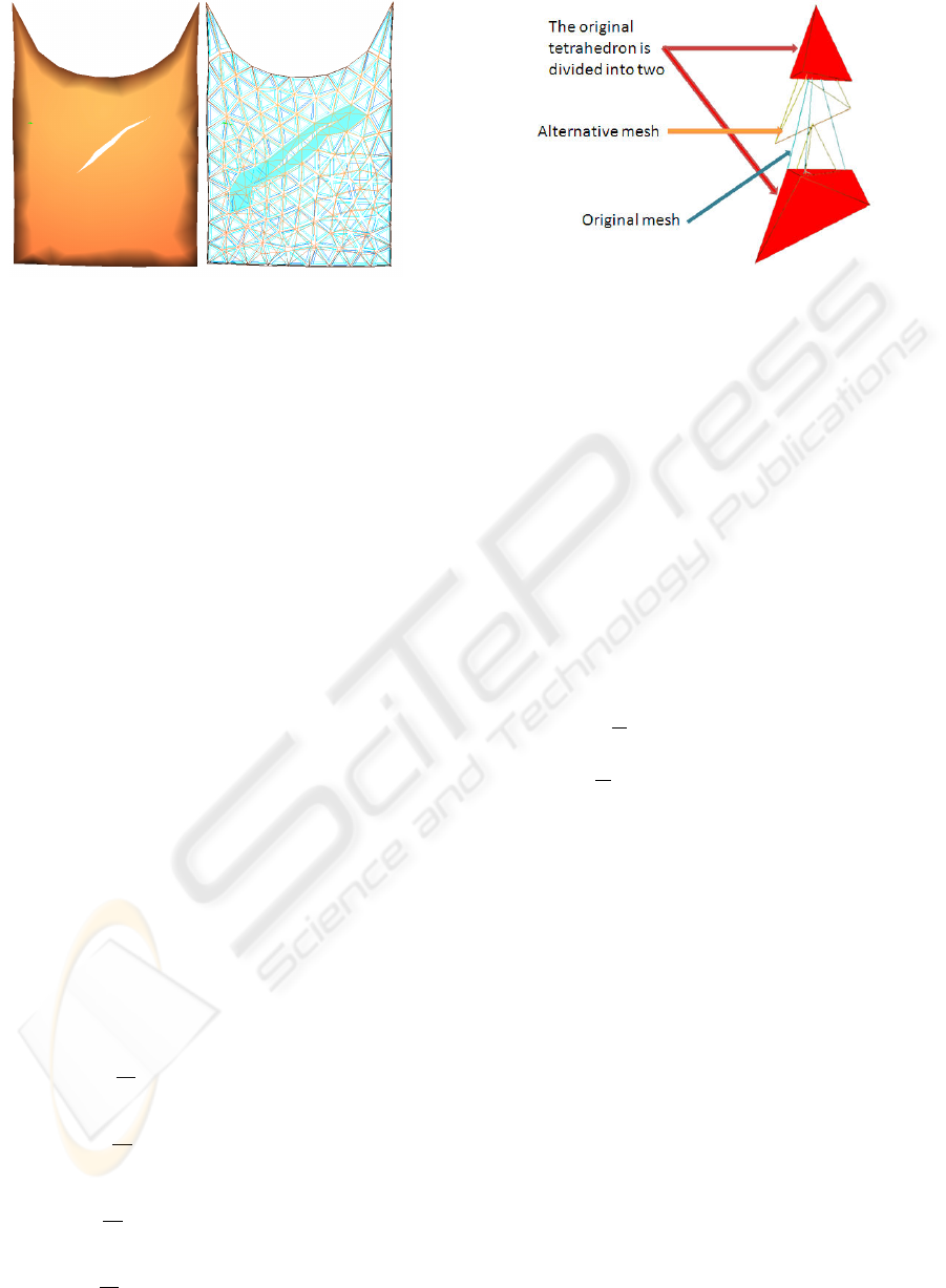
Figure 2: The XFEM adds new DOFs allowing to simulate
discontinuities on the elements. This figure shows the orig-
inal physical mesh composed by tetrahedral elements, this
mesh continues even after the elements are split, those orig-
inal elements must be hidden, showing only the cut of the
model.
time applications. This formulation allows us to in-
clude large deformations using a Cauchy’s strain ten-
sor. We employ the the co-rotational XFEM formula-
tion given by (Je
ˇ
r
´
abkov
´
a and Kuhlen, 2009).
The forces in the co-rotational XFEM, must con-
sider that the rotation of a discontinuous element will
have different behavior in each part of the cutting
plane (above and below). The rotation for the part
above of the cut plane is denoted as R
a
and the ro-
tation below as R
b
; the equations of the deformation
forces of the co-rotational XFEM are defined as
f
X
i
=
n
∑
j=1
R
a
Z
V
a
B
XT
i
cB
X
j
dV (R
T
a
p
X
j
− p
X
0 j
)
}
Above
+
n
∑
j=1
R
b
Z
V
b
B
XT
i
cB
X
j
dV (R
T
b
p
X
j
− p
X
0 j
)
}
Below
(1)
where B
X
i
is the strain matrix defined as B
X
=
[B
1
··· B
n
ψ
1
B
1
···ψ
n
B
n
] where n is the number of
element nodes; c is a matrix of material properties.
From the above equation, the equations of the defor-
mation forces of the standard DOFs and the added
DOFs can be computed separately as follows
f
i
=
V
a
V
R
a
n
∑
j=1
K
i j
(R
T
a
p
a j
− p
0 j
)
+
V
b
V
R
b
n
∑
j=1
K
i j
(R
T
b
p
b j
− p
0 j
)
(2)
f
a
i
=
V
a
V
R
a
Ψ
ai
n
∑
j=1
K
i j
(R
T
a
p
a j
− p
0 j
)
+
V
b
V
R
b
Ψ
bi
n
∑
j=1
K
i j
(R
T
b
p
b j
− p
0 j
)
(3)
Figure 3: When an element is divided, the alternative mesh
is generated with the new virtual elements formed by the
added DOFs, this mesh allows to create a visual mapping to
show the corresponding volume. Note that in the alternative
mesh the virtual elements can overlap, however, this mesh
is only required to make the association of topologies easier.
where the positions of the element nodes are calcu-
lated
p
s j
= p
0 j
+ u
j
+ Ψ
s j
a
j
where s = a or s = b (4)
where the subscript s indicates that it can be applica-
ble for the parts above and below the cut plane.
In order to directly obtain the physical position of
the DOFs we use the shifted enrichment function (see
eq. 9); as a result the deformation forces of the added
DOFs yield
f
a
i
=
∑
n
j=1
−
V
b
V
R
b
K
i j
(R
T
b
p
b j
− p
0 j
) if H
i
= +1
∑
n
j=1
V
a
V
R
a
K
i j
(R
T
a
p
a j
− p
0 j
) if H
i
= −1
(5)
and the positions of the element nodes
p
a j
=
p
0 j
+ u
j
if H
j
= +1
p
0 j
+ u
j
+ a
j
if H
j
= −1
p
b j
=
p
0 j
+ u
j
− a
j
if H
j
= +1
p
0 j
+ u
j
if H
j
= −1
(6)
Employing the framework of the co-rotational
FEM proposed by (Nesme et al., 2005), thus we never
store the whole stiffness matrix, instead, we generate
the displacements by computing the dynamic equa-
tion of the FEM updating the strain matrix and com-
puting directly the forces as is shown in eq. 1. To
obtain the rotation values we use polar decomposition
as is explained by (M
¨
uller and Gross, 2004).
3.2 Mapping Method
Considering topological changes, the XFEM adds
DOFs each time a discontinuity appears remaining the
XFEM FRAMEWORK FOR CUTTING SOFT TISSUE - Including Topological Changes in a Surgery Simulation
277
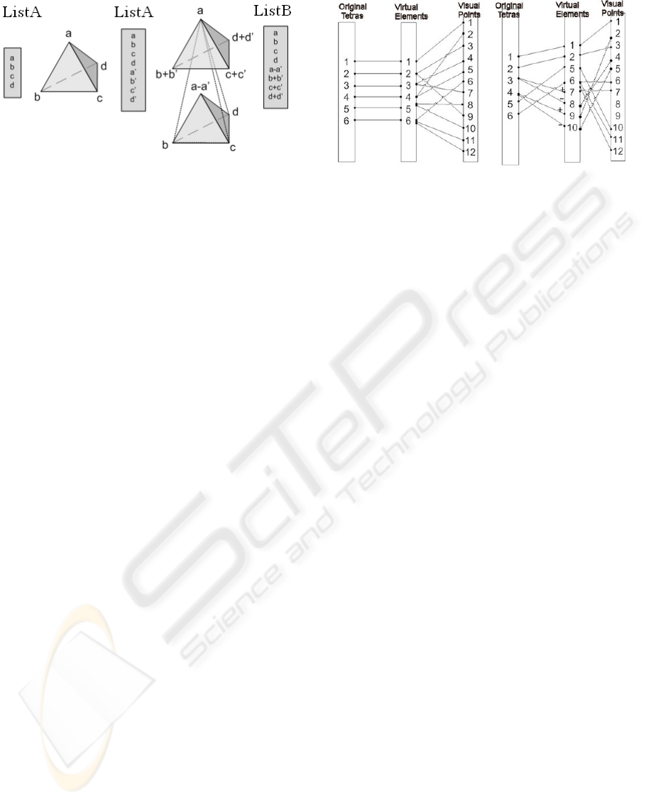
Figure 4: Added DOFs. The original nodal displacements
(on the left) of a tetrahedron are four, when the tetrahedron
is split new DOFs are added (list on the middle); in order to
use the less memory, the alternative mesh stores in the place
of the added DOFs the real position of the vertexes of the
virtual tetrahedron(on the right).
number of elements of the original mesh; thus, an el-
ement is divided using the values of the added DOFs.
Then, how should the triangular mesh be associated
to the tetrahedrons that do not explicitly exist? If the
association of visual points with the physical points
(mapping) is done directly to the original mesh (initial
FEM mesh), the result will not be correct, because the
discontinuous elements do not show the same physi-
cal meaning of the original.
We propose a FEM-XFEM mapping that allows us
to easily control the discontinuous elements; it con-
sists in creating an alternative tetrahedral mesh that
inserts elements each time the element is subdivided
as shown in Figure 1 and Figure 3. The alternative
mesh will always have the same number of DOFs
as the original mesh, storing only the real values of
the vertexes of the new tetrahedrons (i.e. virtual el-
ements) as is shown in Figure 4, which are classified
according to the side of the cut plane (i.e. above or
below). Note that if an element is split, the mapping
method creates two new virtual elements in the same
place, for that reason, it is necesary to identify them
in order to avoid mapping errors.
Another important advantage of the alternative
topology is its speed that takes to reassign the visual
or collision mesh nodes to their corresponding phys-
ical tetrahedron when a cut occurs by recording the
points associated to the tetrahedron of the alternative
mesh as is shown in Figure 5. The alternative mesh
is controlled directly from the physical topology; in
this manner, all the changes in the alternative mesh
are quickly performed and also the search of associ-
ated elements is fairly straightforward. The vertices
of the alternative topology are not DOFs; thereby, the
alternative mesh does not harm the performance of the
simulation.
Figure 5: Initially the association of points is direct, and is
updated when an element is cut. For instance the elements 3
and 4 are cut, then, two new virtual tetrahedrons are created
for each element (4 in total); after, the visual points (only
those connected with the discontinuous elements) must be
re-associated to its tetrahedrons considering the cut plane
(above + or below −).
3.3 Cutting Algorithm
A progressive cut generates many unnecessary faces
of very small sizes, instead we split the tetrahedron
until the tool crosses the whole element obtaining a
semi-progressive cut because there is a delay before
showing the incision. For a well refined mesh the de-
lay in the semi progressive cut can be considered suit-
able in surgical simulations as is shown in Sec.4.3.
When the interactive tool touches a tetrahedron (indi-
cated by the collision detection algorithm), the nearest
tetrahedron to the collision point is sought, right af-
ter, all the neighbors of the tetrahedron are stored in a
list which is used to find the next tetrahedron touched
by the cutting tool. Employing the collision detection
and the assignation of points, it is possible to quickly
extract the list of neighbors for the collided region.
If an element has three crossed edges, it can be
cut; however, it is needed to ensure that the three in-
tersections must be in different edges, the error may
happen if the tool trembles while cutting.
L1,L2,L3 //elements with 1,2,3 intersections
collisionEvent (collisionPoint)
{
if the cut starts
FirstPoint = collisionPoint
T=nearest(Mesh, FirstPoint)//nearest tetra
else //while cutting
listNT = neighbors(T); //neighbors of T
Tc = nearest (listNT, fistPoint)
SecondPoint = CollisionPoint
semiProgressiveCut(Tc)
}
semiProgressiveCut(T0)
{
cq=generateQuad(Tool)//collision quad
GRAPP 2010 - International Conference on Computer Graphics Theory and Applications
278

Figure 6: The collision quad generated by the cutting tool
crosses multiple tetrahedrons in one time, the internal mesh
is created by connecting intersected points on the element
edges.
lT = neighbors(T0)
for each T in lT
for each edgeT in edges(T)
if Intersects(edgeT, cq,intersectionPoint)
if exists T in list L2
L3.add(L2.p1,L2.p2,intersectionPoint)
L2.delete(T)
else
if = exists T in list L1
L2.add(L1.p,intersectionPoint)
L1.delete(T)
else
L1.add(T,intersectionPoint)
L1.add(T,intersectionPoint)
for = each tetra j in L3
createXFEM(j)
L3.clear
FirstPoint = SecondPoint
}
The cut is achieved by the intersection of a colli-
sion quad that specifies the trajectory and deepness of
the tool; this quad is updated if the size is higher of a
value specified by a constant, this size helps to avoid
to re-compute the execution of the algorithm if the
tool continues on the same point. We obtain better re-
sponses if the size of this quad is approximated to the
average sizes of the elements. The cutting algorithm
is presented in Figure 14.
When an element is divided into two new virtual
elements, the visual and collision mapping methods
are called to be updated. Therefore, the visual and
collision meshes must also divide its element accord-
ing to the cut plane and be assigned to its correspond-
ing virtual element.
Note that if the quad of collision is long, in a well
refined mesh the number of tetrahedrons to split is
higher and there is possibly at least one that is not
a neighbor to the reference tetrahedron; consequently,
we can search in a neighborhood on more levels in
order to obtain the higher list of tetrahedron to com-
pare, this level must be specified depending on the
Figure 7: The collision model is mapped to the alternative
mesh, not necessarily on the surface of the elements; it can
be in the corresponding part of volume. The external object
can overlap the elements, colliding in the collision triangle.
maximum size of the collision quad (defined by the
tool blade). The precision of the trajectory of the tool
blade will be better as a smaller quad of collision is
chosen.
The physical, visual and collision topologies are
different from each other, commonly the visual mesh
is more refined to obtain a better look of the model,
however, it is very possible that the triangular edges
(visual topology) do not coincide with the edges of
the tetrahedral elements at the time of cutting; given
these facts, we execute the algorithm for the physical
and visual topologies in an independent manner.
3.4 Visual Mapping
The barycentric mapping is used to connect the alter-
native mapping and the visual mesh; this mapping is
only applied to show the portions of material associ-
ated to the virtual elements. In order to show how the
object is opening while cutting, we use subdivision,
despite its creation of points in each cut; these points
do not strongly impact the simulation performance.
In 3D environments the deepness must be consid-
ered, therefore, when a cut happens an internal mesh
must also be created and mapped. To this end, the new
mesh is easily created by connecting the intersection
points of the edges of the virtual tetrahedron as shows
the Figure 6. Note that if the material is very thin, it
is possible that the tool crosses both sides of the body,
requiring the subdivision and the remapping of both
sides.
The connection of visual points give place to two
different possibilities, searching if a point with the
same value and in the same side of the cut plane al-
ready exists, if this point is found it is used to gener-
ate the new triangular faces; if no point is found then
it is required to search in the list of future points to
be created, avoiding the generation of two points in
the same edge and place. The list of future points is
generated if the collision quad cuts more than one ele-
ment at the same time (considering also the deepness).
XFEM FRAMEWORK FOR CUTTING SOFT TISSUE - Including Topological Changes in a Surgery Simulation
279
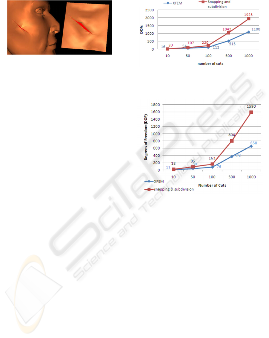
Figure 8: Cutting the skin in a triangular mesh (2D).
Tetrahedra can be split in different manners as is
shown by (Steinemann et al., 2006), in the case the
element is split with a face of four points, then two
new triangles must be generated using the Delaunay
triangulation.
3.5 Collision Detection
The collision detection algorithm must be mapped to
the alternative mesh; then, if a collision appears, the
values of the forces can be sent directly to the corre-
sponding virtual tetrahedrons and the alternative mesh
will propagate the forces to the original elements, fol-
lowing with the XFEM equations.
The added DOFs of a discontinuous element that
shares an edge of non-discontinuous element, is set
to zero, fixing the point on the corresponding edge,
this means, that the added DOF works only when the
neighbors (of edge) is also discontinuous.
A virtual element is able to collide only on the cor-
responding part of volume, this means that the col-
lision method only manages the forces of that spe-
cific part and the virtual element helps to obtain the
barycentric coordinates associated to collision ele-
ments in order to be deformed correctly (see Figure
7).
4 IMPLEMENTATION
In order to evaluate the approach in a medical con-
text, the responses of the approach is tested in an open
surgery. The approach can be analyzed specifically
by simulating the cut of the skin; thus, it is possible to
observe the responses of the XFEM exposed to many
elements that are small and thin (i.e. low volume),
and thereby, the robustness of the approach can be
confirmed by the avoidance of sliver. The material
parameters of the skin used to test the approach con-
siders a Young’s modulus as 1 × 10
4
Pa, Poisson ratio
of 0.3 and the density of 1000kg/m
3
.
SOFA framework is used to implement the ap-
proach (Allard et al., 2007). In SOFA, a single object
Figure 9: Generation of DOFs (2D): comparing XFEM and
Snapping and Subdivision. While the second one impacts
the performance, the XFEM simulates an approximated ac-
curacy improving the performance of the simulation.
Figure 10: Generation of DOFs(3D): comparing XFEM and
Snapping and Subdivision. This figure shows the increase
of DOFs when the blade cuts tetrahedral elements. The test
has been performed using continuous cuts.
can be represented by multiple geometrical models
that are connected through mappings (e.g. barycen-
tric mapping).
4.1 2D: Human Face Skin
A human face model, represented with triangular ele-
ments, is compared with a method already included in
SOFA (i.e. the snapping and subdivision). The Fig-
ure 9 shows that the XFEM generates less DOFs than
snapping and subdivision; this difference increases as
the number of cuts increase. Therefore, the XFEM
allows to simulate physically the discontinuities with-
out harming the performance and the simulation sta-
bility; some images of the simulation are shown in
Figure 8
GRAPP 2010 - International Conference on Computer Graphics Theory and Applications
280
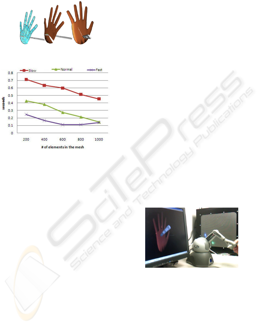
Figure 11: The tetrahedral model of the hand can be cut
interactively.
Figure 12: The delay of crossing an element considering
different speeds and meshes.If the number of cuts incre-
ments the processing time also increases, impacting the per-
formance of the simulation.
4.2 3D: Hand Skin
The test consists of cutting the skin of the dorsal part
of hand; this procedure can be applicable in differ-
ent surgeries (e.g. lipoma removal). The thickness of
the skin of the hand is from 0.5 mm to 2 mm in soft
regions (Schmidt, 2003), we choose to use 2 mm as
thickness of the skin to observe the deepness of the
object.
In 3D, the physical topology is represented by a
tetrahedral mesh; the visual and collision topologies
are represented by a triangular surface mesh. The
hand model is tetrahedralized employing the mesh
generator called tetgen; the force feedback is obtained
using the phantom omni. The comparative with snap-
ping and subdivision is presented in Figure 10.
4.3 Other Remarks
In order to generate a real time simulation the time
step will be dynamically adapted according to the pro-
cessing charge. Using an implicit method ensures the
stability for all the supported simulation time steps.
The resultant images of the simulation of the skin de-
formed and dissected are shown in Figure 11 and Fig-
ure 13. Moreover, the skin can be used together with
other models to simulate an open surgery as is ex-
pressed in Figure 15.
As we are using a semi-progressive cutting we an-
alyze the Framework in a very conventional PC with
a processor Intel Core 2Duo 2GHz, RAM memory of
2G, the delay depends basically on the refinement of
the physical mesh, the speed of the user while cuts
and the speed of the execution of the algorithms, as is
shown in Figure 12.
5 CONCLUSIONS
In this paper, a framework focused on the efficient ap-
plication of the XFEM has been designed; this frame-
work includes the embedded design of an alternative
mapping method, that allows associating, in an easy
and direct manner, the diverse topologies when the
cut of an element appears. The mapping also stores
the association of point-tetra, which makes the update
of the assignation of visual or collision points faster
(i.e. vertices), with its corresponding virtual element
while the user is cutting; all these, considering the
side of the cut plane. Also, a semi progressive cutting
algorithm has been created. Additionally, a variety
of meshes in 2D and 3D were tested obtaining con-
siderable differences in the creation of nodal DOFs,
in consequence, it is proved that the XFEM does not
strongly impact the simulation performance, allowing
real-time simulations.
Figure 13: Interactive surgery simulation considering topo-
logical changes in real time.
However, there are many important aspects to deal
with that have not been considered such as: self-
collisions of discontinuous elements, multi-resolution
techniques, textures in the internal mesh, creation of a
fully-progressive cutting algorithm and parallelism of
the methods. All these aspects are left as future work.
This work was completely focused on the XFEM,
obtaining a simulation that fulfill with stability, accu-
racy, interactivity and real time; which are the proper-
ties required for a virtual surgery simulation.
XFEM FRAMEWORK FOR CUTTING SOFT TISSUE - Including Topological Changes in a Surgery Simulation
281

The inclusion of this framework will make the
generation of more complex simulations possible, in
which the interaction of diverse models (organs) that
act together can be possible and, in this manner, de-
sign simulations with major impact in the medical
area, such as the extraction of a tumor or the fully
physical modeling of one part of the body.
ACKNOWLEDGEMENTS
We would like to thank SOFA Team for the help they
bring. We also Graham Maslin for sharing the scalpel
model.
REFERENCES
Allard, J., Cotin, S., Faure, F., Bensoussan, P.-J., Poyer,
F., Duriez, C., Delingette, H., and Grisoni, L. (2007).
Sofa - an open source framework for medical simula-
tion. In Medicine Meets Virtual Reality (MMVR).
Babuska, I. and Melenk, J. M. (1997). The partition of unity
method. International Journal of Numerical Methods
in Engineering, 40:727–758.
Belytschko, T. and Black, T. (1999). Elastic crack growth
in finite elements with minimal remeshing. Interna-
tional Journal of Numerical Methods in Engineering,
45(5):601–620.
Bielser, D., Glardon, P., Teschner, M., and Gross, M.
(2003). A state machine for real-time cutting of tetra-
hedral meshes. In Pacific Graph., pages 377–386.
Forest, C., Delingette, H., and Ayache, N. (2005). Remov-
ing tetrahedra from manifold tetrahedralisation : ap-
plication to real-time surgical simulation. Medical Im-
age Analysis, 9(2):113–122.
Je
ˇ
r
´
abkov
´
a, L. and Kuhlen, T. (2009). Stable cutting of de-
formable objects in virtual environments using xfem.
IEEE Comput. Graph. Appl., 29(2):61–71.
Linblad, A. and Turkiyyah, G. (2007). A physically-based
framework for real-time haptic cutting and interaction
with 3d continuum models. SPM.
Molino, N., Bao, Z., and Fedkiw, R. (2004). A virtual node
algorithm for changing mesh topology during simula-
tion. ACM Trans. Graph. (SIGGRAPH Proc, 23:385–
392.
M
¨
uller, M. and Gross, M. (2004). Interactive virtual materi-
als. In Proceedings of the 2004 conference on Graph-
ics interface, pages 239–246.
Nealen, A., M
¨
uller, M., Keiser, R., Boxerman, E., and Carl-
son, M. (2005). Physically based deformable models
in computer graphics. Eurographics 2005 State of the
Art Report.
Nesme, M., Kry, P. G., Je
ˇ
r
´
abkov
´
a, L., and Faure, F. (2009).
Preserving topology and elasticity for embedded de-
formable models. In ACM Transactions on Graphics
(Proc. of SIGGRAPH). ACM. to appear.
Nesme, M., Payan, Y., and Faure, F. (2005). Efficient, phys-
ically plausible finite elements. In Dingliana, J. and
Ganovelli, F., editors, Eurographics (short papers).
Schmidt, H.-M. (2003). Surgical anatomy of the hand.
Thieme.
Serby, D., Harders, M., and Szkely, G. (2001). A new ap-
proach to cutting into finite element models. In Med-
ical Image Computing and Computer Assisted Inter-
vention (MICCAI), number 2208 in LNCS, pages 425–
433. Springer-Verlag.
Sifakis, E., Der, K. G., and Fedkiw, R. (2007). Arbi-
trary cutting of deformable tetrahedralized objects. In
2007 ACM SIGGRAPH / Eurographics Symposium on
Computer Animation, pages 73–80.
Steinemann, D., Harders, M., Gross, M., and Szekely, G.
(2006). Hybrid cutting of deformable solids. In
Proceedings of the IEEE Virtual Reality Conference,
pages 425–433.
Turkiyyah, G., Karam, W. B., Ajami, Z., and Nasri, A. H.
(2009). Mesh cutting during real-time physical simu-
lation. In Symposium on Solid and Physical Modeling,
pages 159–168.
Vidal, F., Bello, F., Brodlie, K., John, N., D.Gould, Philips,
R., and Avis, N. (2006). Principles and aplications of
computer graphics in medicine. Computer Graphics,
pages 113–137.
Vigneron, L. M., Verly, J. G., and Warfield, S. K. (2004).
Modelling surgical cuts, retractions, and resections
via extended finite element method. In Proceed-
ings of Medical Image Computing & Computer As-
sisted Intervention, volume 7 of LNCS, pages 311–
318. Springer Verlag.
APPENDIX A. EXTENDED FINITE
ELEMENT METHOD (XFEM)
The main idea of exploiting the partition of unity
property is to construct basis functions through prod-
ucts of classical shape functions and a local enriched
basis; allowing to generate discontinuous elements.
Hence, the equation of the displacements can be cal-
culated as
u(x) =
n
∑
i=1
Φ
i
(x)u
i
|
{z }
classical
+
n
∑
j=1
Φ
j
(x)ψ
j
(x)a
j
| {z }
enrichment
(7)
where Φ
i
(x) are the clasical shape functions; the
discontinuous enrichment functions are denoted by
ψ
j
(x), and the new nodal DOFs as a
j
. The enrich-
ment function ψ(x) can be any discontinuous func-
tion; commonly, it is the Heaviside function (Eq. 8),
another option is the shifted function defined in Eq. 9.
GRAPP 2010 - International Conference on Computer Graphics Theory and Applications
282
Ψ(x) = H(x) =
+1 above the crack
−1 below the crack
(8)
ψ
i
(x) =
1
2
(H(x) − H
i
) (9)
where H
i
is the value of Heaviside function at the i-
th node. The shifted function consists in using the
enrichment contribution only inside of the discontin-
uous element and ignores the contribution on the bor-
ders and outside of the element.
To keep the delta property, the displacements of
the enriched nodes has to be computed as the sum
of the components u
i
+ Ψ
i
a
i
. The shifted function in
contrast with the Heaviside, directly stores the values
of the displacement in u
i
and the added DOFs a
i
are
only required to establish the displacements of an en-
riched element.
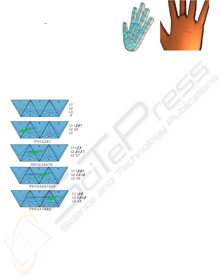
Figure 14: Cutting algorithm: elements 1-5 are frontal el-
ements and 6-9 internal elements. When the cut starts, the
first element found is tetrahedron 1, its neighbors are ob-
tained and stored in list lT (list of tetrahedrons), the neigh-
bors are obtained considering all tetrahedrons that share at
least one vertex. For all neighbors, we search those whose
collide with the collision quad. If an element has one, two
or three edges intersecting are stored respectively in lists
L1,L2,L3. After crossing an element, a new internal mesh
is created considering the intersection points. If an element
is recorded in list L2 or L3 must be deleted from the previ-
ous list. In order to ensure that the element is fully crossed,
the crossed edges of the element must be different from the
others stored in list.
Figure 15: The skin of the hand can be used to simulate an
open surgery.
APPENDIX B. CO-ROTATIONAL
FEM
The corotational method is based on the linear FEM
using Cauchy’s strain tensor; this method stores a ref-
erence state of the elements. To compute the deforma-
tion forces, these have to be translated to the reference
state and rotated back to the current state. Therefore,
the deformation forces are expressed as follows
f
i
= R
n
∑
j=1
K
i j
(R
T
p
j
− p
0 j
) (10)
where R is the rotation matrix is required to translate
from the current to initial state, p are the positions of
the element nodes in the current deformed state de-
fined as p = p
0
+ u, in which p
0
indicates the initial
positions of the element nodes.
XFEM FRAMEWORK FOR CUTTING SOFT TISSUE - Including Topological Changes in a Surgery Simulation
283
