
A THREE-LEVEL ARCHITECTURE FOR MODEL–FREE
DETECTION AND TRACKING OF INDEPENDENTLY
MOVING OBJECTS
Nicolas Pugeault
1
, Karl Pauwels
2
, Mark M. Van Hulle
3
, Florian Pilz
4
and Norbert Kr
¨
uger
5
1
University of Surrey, U.K.
2,3
Katholieke Universiteit Leuven, Belgium
4
Aalborg Universitet Copenhagen, Denmark
5
University of Southern Denmark, Denmark
Keywords:
Motion detection, 3D reconstruction, Egomotion, Independently moving objects.
Abstract:
We present a three–level architecture for detection and tracking of independently moving objects (IMOs) in
sequences recorded from a moving vehicle. At the first stage, image pixels with an optical flow that is not
entirely induced by the car’s motion are detected by combining dense optical flow, egomotion extracted from
this optical flow, and dense stereo. These pixels are segmented and an attention mechanism is used to process
them at finer resolution at the second level making use of sparse 2D and 3D edge descriptors. Based on the
rich and precise information on the second level, the full rigid motion for the environment and for each IMO
is computed. This motion information is then used for tracking, filtering and the building of a 3D model of
the street structure as well as the IMO. This multi-level architecture allows us to combine the strength of both
dense and sparse processing methods in terms of precision and computational complexity, and to dedicate
more processing capacity to the important parts of the scene (the IMOs).
1 INTRODUCTION
Independently moving objects (IMOs), such as cars,
bicycles and pedestrians represent a major source of
hazard while driving, and detecting and tracking them
is therefore a critical task for an automated driving
system. Although this task is performed effortlessly
by humans, its implementation in an artificial system
demands the solving of several difficult vision prob-
lems. First comes the problem of actually detecting
moving objects in the scene. Although there exist ro-
bust solutions for this problem in the case of a static
camera (e.g., (Leibe et al., 2008)), the moving cam-
era version is considerably more difficult. Recent ap-
proaches have used model–based detection with very
good results (Leibe et al., 2008). One limitation
of such approaches is the difficulty to detect IMOs
early on. Far objects will be described by smaller
patches in the image, that will be difficult to match
with the model. Another limitation is that moving ob-
jects for which no model is provided will not be de-
tected and will be simply ignored by the system. The
present work presents a model-free detection mecha-
nism, and is therefore more general. A second prob-
lem is tracking multiple objects simultaneously. Some
methods use world knowledge to guide the tracking
and simplify the problem (ground plane, perspective,
see (Hoiem et al., 2007; Hoiem et al., 2008)). Third,
combining early detection with real time processing
enables the system to plan early and react appropri-
ately to driving situations. There arises a dilemma,
because early detection and interpretation of visual
information requires high resolution images, which
increases the processing load. For this reason, it is
desirable to have an attention mechanism that allows
the system to focus limited processing resources to
moving objects, just as humans perceive regions cor-
responding to independent motion as highly salient
(Rushton et al., 2007).
The problem of tracking multiple independent tar-
get simultaneously has been studied for a long time,
e.g., Bar-Shalom reviewed early attempts in (Bar-
Shalom, 1978). The key problem faced by multiple
targets data association is the exponential complex-
237
Pugeault N., Pauwels K., M. Van Hulle M., Pilz F. and Krüger N. (2010).
A THREE-LEVEL ARCHITECTURE FOR MODEL–FREE DETECTION AND TRACKING OF INDEPENDENTLY MOVING OBJECTS.
In Proceedings of the International Conference on Computer Vision Theory and Applications, pages 237-244
DOI: 10.5220/0002838002370244
Copyright
c
SciTePress
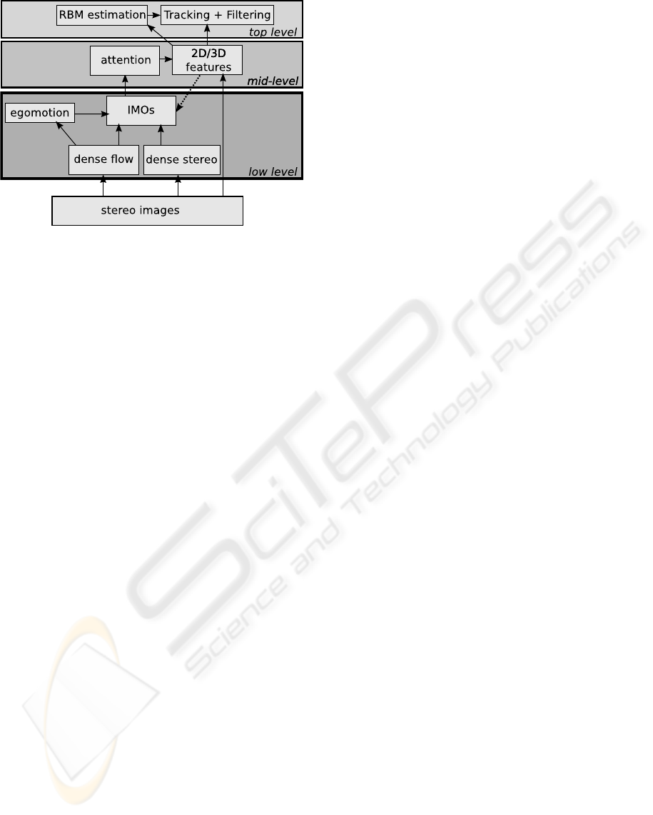
Figure 1: Illustration of the architecture presented in this
paper.
ity of the exhaustive approach. A more sophisticated
approach was proposed by Reid’s Multi-Hypothesis
tracking (MHT) (Reid, 1979). Cox (Cox, 1992) re-
viewed both approaches, focusing more on the data
association problem, and extended the single target
Probabilistic Data Association Filter (PDAF) to mul-
tiple targets, called Joint Probabilistic Data Associa-
tion Filter (JPDAF). Betke et al. (Betke et al., 2000)
proposed a multiple target tracking method with a
complexity linear to the number of targets, that was
applied on driving scenes recorded on American and
German highways. The car detection is done either:
(1) by image differentiation (only works with nearby
cars); (2) a model-based approach driven by a two
step search (first, the system looks for long edges, that
are then verified against a car template). Comaniciu et
al. (Comaniciu et al., 2003) focus on the issue of tar-
get’s representation and localisation, in a kernel-based
framework. Their approach dwells on the representa-
tion of 2D deformable objects whereas our focus is
on the generation and use of 3D model information.
Leibe et al. (Leibe et al., 2008) proposed a model–
based system for coupled detection and tracking of
multiple objects. Lourakis et al. (Lourakis et al.,
1998) used a sparse set of points to detect indepen-
dent motion from the residual planar parallax normal
flow field. Sawhney et al. (Sawhney et al., 2000)
combine both the epipolar and the shape consistency
constraint to derive a sparse geometric solution for in-
dependent motion detection. Moreover, there exist
on-line and commercial systems (e.g., (Bertozzi and
Broggi, 1998)) for lane and obstacle detection, but
those systems mainly make use of low resolution im-
ages to provide real–time processing, and could ben-
efit from the multiple layer attention mechanism pre-
sented herein.
In this article, we present a three layer system that
makes use of such an attention mechanism, illustrated
in Fig. 1. The first layer combines multiple visual
cues (dense stereo and optic flow) to segment the im-
age motion into parts that result from self–motion in
the static environment, and parts that are due to the in-
dependent motion. From this detection stage, Regions
of Interest (ROIs) describing the IMOs are defined.
The second level extracts 3D features using stereop-
sis, processing the background at low resolution and
the ROIs at high resolution. IMOs containing little
structure are discarded at this stage. This is symbol-
ised in Fig. 1 by the dashed arrow between the middle
and lower levels. The upper level of our approach is
concerned with simultaneously tracking and building
a feature–based model of the IMOs (similarly to (Dis-
sanayake et al., 2001; Montemerlo et al., 2002; Thrun
et al., 2004)).
We have evaluated our data set on a
very challenging publicly available data set
(http://www.mi.auckland.ac.nz/eisats) for which
ground truth of IMOs is provided. We can show that
by making use of the multi-level architecture, we are
able to increase performance significantly compared
to just using a the first level mechanism. We can also
show on examples, that we are able to compute the
3D motion as well as the street structure in a way that
allows for the computation of the relative 3D motion
of the IMO compared to the street structure.
The novel aspects of this work are: (i) Model–
free: the system does not rely on object models
but instead automatically builds IMO models; (ii)
Attention–based: the system uses attention to allocate
resources efficiently, and especially processes IMOs
at higher resolution; and (iii) Hybrid: the proposed
system makes use of a hybrid approach, where the
dense layer provides model-free IMO detection, and
the feature based layer is used to discard outliers and
build and track IMOs’ models. In this way, we can
combine computational efficiency with reliable and
precise motion and object modeling.
2 METHODS
In section 2.1 we present the lower level of our sys-
tem, that uses dense image processing to identify
IMOs in the image. In section 2.2 we present the fea-
ture based part of our system. Finally, in section 2.3
we present the IMO–based attention mechanism we
implemented.
2.1 Detection of Independent Motion
Attributing image motion to moving objects is rela-
tively straightforward when the observer is static, but
VISAPP 2010 - International Conference on Computer Vision Theory and Applications
238
(b) dense stereo disparity
(a) optical flow
(c) IMO detection (d) simple IMO tracking
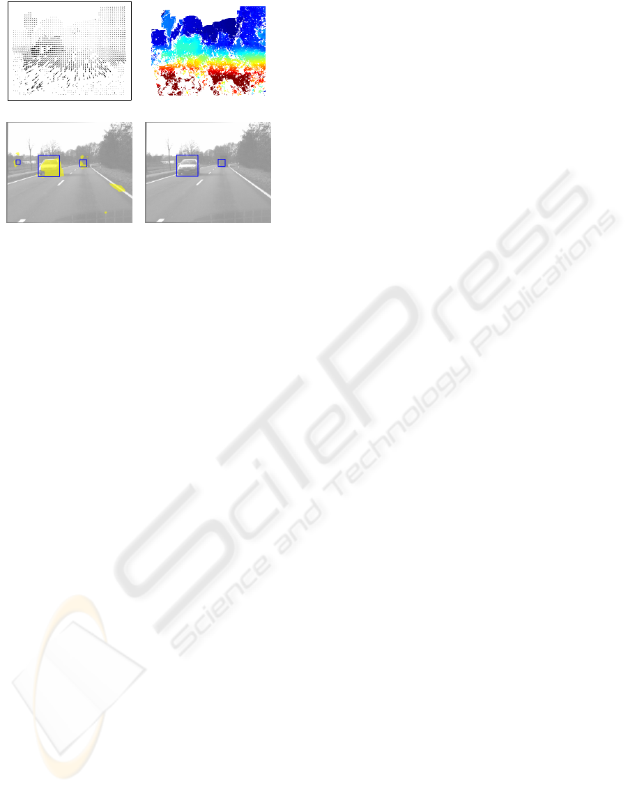
Figure 2: Illustration of the IMO detection level: a) the op-
tical flow; b) the dense disparity; c) the low-level indepen-
dent motion measure (yellow) and the detected IMOs after
world-knowledge integration (blue boxes); d) the IMOs re-
maining after the simple tracking stage.
when the observer is moving, both moving objects
and static environment generate image motion, and
multiple cues must be combined to discriminate be-
tween both origins.
2.1.1 Visual Cue Combination
In our system, a pixelwise measure of independent
motion is obtained on the basis of inconsistencies be-
tween the low-level cues dense optical flow (com-
puted in the left image only), dense binocular dispar-
ity and camera motion, similar in spirit to (Thomp-
son and Pong, 1990). We use phase-based techniques
for the optical flow (Pauwels and Van Hulle, 2009)
and disparity (Sabatini et al., 2007) estimation, and
a continuous-time algorithm for the egomotion esti-
mation (Pauwels and Van Hulle, 2006). The latter
operates on the monocular optical flow field. Ex-
ample optical flow and dense disparity results are
shown in Figs. 2 a) and 2 b). These algorithms
were chosen for their robustness to the nuisance fac-
tors typically encountered in real-world driving situ-
ations. In addition, GPU-based real-time implemen-
tations are available for the optical flow and dispar-
ity algorithms (Pauwels and Van Hulle, 2008). At
each pixel x = (x, y)
T
, a measure of independent mo-
tion, I(x), is obtained by subtracting the optical flow
component that results from the self-motion in the
static environment from the estimated optical flow
field u(x) = (u
x
, u
y
)
T
:
I(x) = ku(x) − d
D
(x)A(x)t − B(x) ω
ω
ωk . (1)
where d
D
(x) is the inverse depth obtained from dense
disparity, and t = (t
x
, t
y
, t
z
)
T
and ω
ω
ω = (ω
x
, ω
y
, ω
z
)
T
are
the translational and rotational velocity of the moving
observer, robustly estimated from u(x). Furthermore:
A(x) =
−1 0 x
0 −1 y
, (2)
B(x) =
xy −1 − x
2
y
1 + y
2
−xy −x
. (3)
2.1.2 World-knowledge Integration
Spatiotemporal filtering is applied to the measure of
Eq. (1) to reduce the noise. After thresholding, a num-
ber of independent motion blobs are obtained (yellow
blobs in Fig. 2 c)). These blobs give a rough indica-
tion of an IMO’s location. They are however quite
noisy, with a significant number of false positives.
To improve detection performance, these low-level
detections are combined with world-knowledge. In
particular, the ground-plane (as estimated from dense
disparity) and expected object size, are used to obtain
a more precise size and location estimate. In turn,
the low-level cues are used to validate this box esti-
mate (by evaluating the variance of the dense dispar-
ity within the box). The blue boxes in Fig. 2 c) corre-
spond to the IMO-estimates obtained on the basis of
the yellow blobs and the world-knowledge.
Finally, a simple tracking procedure is used that
links the boxes across frames by connecting the detec-
tions to the track that is closest in 3D. Detections that
are not consistently detected over a number of consec-
utive frames are removed. This reduces the number of
false positives. The final detections after the tracking
stage are shown in Fig. 2 d).
2.2 Feature Extraction and Tracking
In this section, we describe the second level of our
system, that is composed of sparsely extracted fea-
tures. The sparseness allows for the use of higher res-
olution (and therefore accuracy) than would be possi-
ble when processing each and every pixel.
2.2.1 Visual Primitives
The main features we use for describing the scene
are local multi-modal edge and line descriptors called
visual primitives (Kr
¨
uger et al., 2004; Pugeault,
2008). These are extracted sparsely from the images
along edges, and additional visual modalities, such as
colour and phase, extracted at these locations are as-
sociated, to form a feature vector:
π
π
π = (x, t, φ, c, f) (4)
where x is the 2D-primitive’s position, t the local tan-
gent to the contour, φ is the local phase, that encodes
A THREE-LEVEL ARCHITECTURE FOR MODEL-FREE DETECTION AND TRACKING OF INDEPENDENTLY
MOVING OBJECTS
239

1)
2)4)
3)
a)
b)
c)
d)
Figure 3: Illustration of the feature extraction level: a)
one image; b) the 2D–primitives extracted; c) a detail of
b); d) symbolic representation of a 2D–primitives, with 1-
orientation, 2-phase, 3-colour, and 4-optical flow.
the contrast transition across the contour (e.g., bright
to dark edge), c encodes colour information on both
sides of the contour (sampled locally), and f encodes
the local optical flow.
Such 2D-primitives are matched across stereo-
pairs of images, allowing for the reconstruction of a
3D equivalent, called 3D-primitives, and described by
the following feature vector:
Π
Π
Π = (X, T, Φ, C) (5)
where X is the 3D-primitive’s position, T the 3D tan-
gent to the contour, Φ is the phase, and C encodes
colour information of the 3D-contour. This process is
illustrated in Fig. 3, where a) shows a detail of the im-
age, b) the extracted 2D-primitives and c) a magnified
detail. In d), the symbolic representation of primitives
is illustrated, with 1) indicating orientation, 2) phase,
3) colour, and 4) optical flow. Moreover, SIFT fea-
tures (Lowe, 2004) are also extracted from the images
to allow for more robust matching.
2.2.2 Rigid Body Motion (RBM) Estimation
The motion of the camera and of the IMOs is eval-
uated using correspondences of 3D-primitives and
SIFT features across time. In this case, because we
consider only vehicles, we restrict ourselves to Rigid
Body Motions (RBMs). The mathematical formu-
lation of the RBM that we use is from (Rosenhahn
et al., 2001), and has three advantages: First, the mo-
tion is optimised in 3D space; second, it allows for
solving the motion jointly for different kind of con-
straint equations that stem from different type of im-
age features (in this case, local edge descriptors and
SIFT); third, it minimises the error directly in SE(3),
and therefore does not require additional measures
to handle degenerate cases. As been shown in (Pilz
et al., 2009), a combination of heterogeneous features
(edges and SIFT features) leads to an improved ro-
bustness and accuracy of the RBM estimate. Outliers
are discarded using RANSAC (Fischler and Bolles,
1981).
2.2.3 Tracking and Filtering
All 3D-primitives are tracked using independent
Kalman Filters (Kalman, 1960). The prediction stage
is provided by the estimated motion. The position un-
certainty of the 3D–primitives is re-projected in the
image domain, into a 2 × 2 covariance matrix. Using
this covariance matrix we estimate the likelihood for
the 3D-primitive to find a match at each location by
a normal distribution combined with a uniform dis-
tribution (that expresses the chance for a correct 3D–
primitive not to be matched). We will write the fact
that a primitive Π
Π
Π
i
that predicts a primitive
ˆ
Π
Π
Π
i,t
at time
t is matched (as described above) as µ
i,t
and evaluate
its likelihood as:
p[µ
i,t
] =
e
1
2
(∆x)
>
i,t
Σ
−1
∆,i,
(∆x)
i,t
(2π)
p
|Σ
∆,i,t
|
+ β (6)
The matrix Σ
∆,i,t
=
ˆ
Σ
x,i,t
+
˜
Σ
x,i,t
is the sum of the re–
projected position uncertainty for both the predicted
(
ˆ
Σ
x,i,t
) and the observed (
˜
Σ
x,i,t
) primitives in this im-
age. In this equation, β = p[¯µ|Π
Π
Π] Also, (∆x)
t
=
ˆx
t|t−1
− ˜x
t
is the difference between the position of
the two re–projected primitives, where ˆx
t|t−1
is the
predicted position and ˜x
t
is the position of the poten-
tial match. If the confidence p [µ
i,t
] is larger than the
chance value γ = p [µ|Π], the the match is considered
valid. Furthermore, the similarity between the prim-
itives (in orientation, phase, and colour) is also con-
sidered, and matches with a too low similarity (lower
than τ = 0.9) are disregarded.
Moreover the confidence in the existence of the
accumulated primitive is updated depending on how
consistently concordant evidence has been found in
the image. The probability is evaluated from
p[Π
Π
Π
i,t
|¯µ
i,t
)] = (1 + κ
i,t
)
−1
, (7)
where κ is evaluated recursively
κ
i,t
=
γ
p[µ
i,t
]
κ
i,t−1
. (8)
with κ
1
= p[Π] is the prior probability that a 3D–
primitive is correct.
If an hypothesis’ confidence p [Π
Π
Π
i,t
|¯µ
i,t
)] falls be-
low a threshold τ
min
, then it is deemed erroneous and
discarded; if it raises above a threshold τ
max
, then it is
deemed verified up to certainty, and its confidence is
not updated any more. This allows for the preserva-
tion of features during occlusion. This is effectively a
soft version of the classical n-scan strategy in tracking
(Reid, 1979).
Based on this filtering process, at the third level
a 3D model of the object becomes accumulated and
a final decision for the acceptance or removal of the
IMO is made.
VISAPP 2010 - International Conference on Computer Vision Theory and Applications
240
sequence T03 sequence S06
-1500
-1000
-500
0
500
200 400 600 800 1000 1200 1400 1600
translation in mm
frame
Drivsco_tour_03#000: Translation Parameters
T
X
T
Y
T
Z
-0.01
-0.005
0
0.005
0.01
200 400 600 800 1000 1200 1400 1600
rotation in radians
frame
Drivsco_tour_03#000: Rotation Parameters
R
x
R
y
R
z
-1500
-1000
-500
0
500
300 400 500 600 700 800 900 1000 1100
translation in mm
frame
s_06a_01#000: Translation Parameters
T
X
T
Y
T
Z
-0.01
-0.005
0
0.005
0.01
300 400 500 600 700 800 900 10001100
rotation in radians
frame
s_06a_01#000: Rotation Parameters
R
x
R
y
R
z
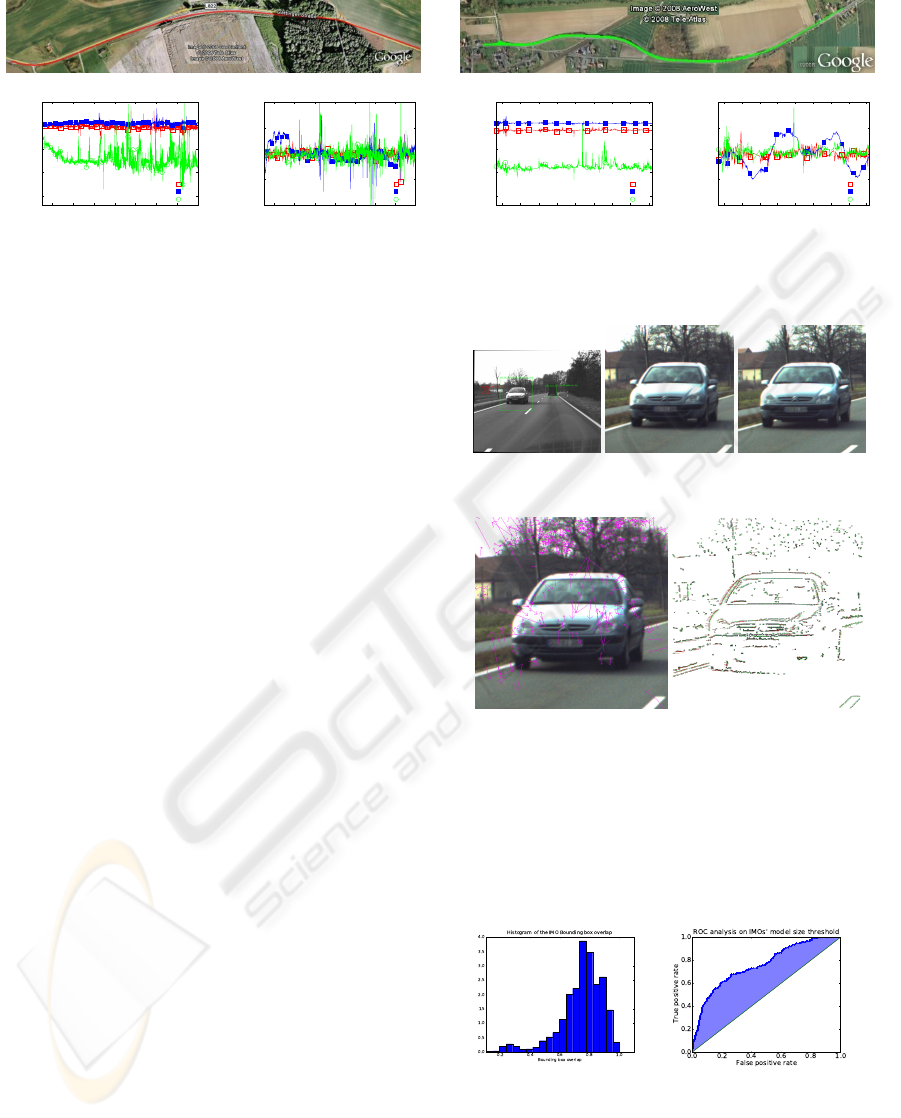
Figure 4: Top: The road on which our system was tested (from Google Earth) Bottom: Estimated vehicle egomotion: the
estimated translation T = (T
X
, T
Y
, T
Z
), and the rotation provided as R = αa
a
a, where α is the rotation angle and a
a
a the axis.
2.3 Attention Mechanism
The complexity of operations at the feature level
grows with the density of extracted features, there-
fore it is desirable to reduce the scale of processing or
to downscale the images to achieve reasonable speed.
On the other hand, when IMOs are very distant to the
camera, they are represented by very small patches in
the image, leading to low accuracy and robustness. In
this work, we implemented a simple attention mech-
anism to optimise resource usage — for a review of
attention mechanisms in computer vision, see, e.g.,
(Caputo and Lombardi, 1995).
The first, pre-attentive, layer of our system ex-
tracts IMOs from dense stereo and optical flow, on
downscaled versions of the images. This is illustrated
in Fig. 5a). The IMO extraction discussed in section
2.1 provides us with a list of attention vectors, of the
form:
A
i,t
= (x, y, w, h) (9)
where (x, y) designates the position of the i
th
IMO in
the left image at time t, w and h the width and height
of a corresponding region of interest (ROI). The posi-
tion in the right image is given by the dense disparity
estimate. The upper, feature–based layer use these
ROIs to process the image at variable resolutions. Ef-
fectively, all ROIs are processed at twice the reso-
lution as the background. The number of extracted
3D–primitives is assessed in each ROI, and ROIs with
there are less than N 3D–primitives are discarded (ex-
periments showed that N = 20 is an ideal value). In
Fig. 5a) a discarded ROI is drawn as crossed in red,
and the valid ones are drawn in green.
3 RESULTS
We have evaluated our system on two video se-
quences recorded on the two Drivsco road sequences
(a) IMO detec-
tion
(b) left ROI (c) right ROI
(d) SIFT features (e) stereo primitives
Figure 5: Illustration of the attention mechanism: In a) the
detected IMOs are denoted by bounding boxes in the im-
age (red for deleted spurious IMOs, green for valid ones).
In b-c), the region of interest (ROI) extracted from the de-
tected IMOs are shown. In d), the red arrows indicate ex-
tracted SIFT features. In e), the red lines indicate stereo-
correspondences of 2D–primitives.
(a) Bounding box accuracy (b) False IMOs rejection
Figure 6: (a) Histogram of the bounding box accuracy. In
this 1 represent a perfect overlap between the detected and
hand–labelled bounding boxes. (b) ROC analysis of the
IMO selection based on the number of 3D–primitives in the
bounding box.
A THREE-LEVEL ARCHITECTURE FOR MODEL-FREE DETECTION AND TRACKING OF INDEPENDENTLY
MOVING OBJECTS
241
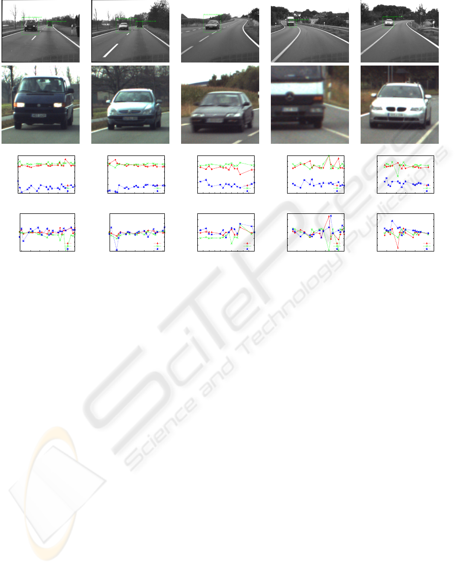
T03-IMO #2 T03-IMO #14 S06-IMO #4 S06-IMO #55 S06-IMO #56
-2000
-1500
-1000
-500
0
500
440 445 450 455 460 465
translation in mm
frame
Drivsco_tour_03#000: IMO_2 - Translation Parameters
T
X
T
Y
T
Z
-2000
-1500
-1000
-500
0
500
645 650 655 660 665 670
translation in mm
frame
Drivsco_tour_03#000: IMO_14 - Translation Parameters
T
X
T
Y
T
Z
-2500
-2000
-1500
-1000
-500
0
500
1000
480 482 484 486 488 490 492 494 496 498 500
translation in mm
frame
s_06a_01#000: IMO_4 - Translation Parameters
T
X
T
Y
T
Z
-2500
-2000
-1500
-1000
-500
0
500
1000
880 885 890 895 900 905 910
translation in mm
frame
s_06a_01#000: IMO_55 - Translation Parameters
T
X
T
Y
T
Z
-2500
-2000
-1500
-1000
-500
0
500
1000
935 940 945 950 955 960 965
translation in mm
frame
s_06a_01#000: IMO_56 - Translation Parameters
T
X
T
Y
T
Z
-0.02
-0.015
-0.01
-0.005
0
0.005
0.01
0.015
0.02
440 445 450 455 460 465
rotation in radians
frame
Drivsco_tour_03#000: IMO_2 - Rotation Parameters
R
X
R
Y
R
Z
-0.02
-0.015
-0.01
-0.005
0
0.005
0.01
0.015
0.02
645 650 655 660 665 670
rotation in radians
frame
Drivsco_tour_03#000: IMO_14 - Rotation Parameters
R
X
R
Y
R
Z
-0.03
-0.02
-0.01
0
0.01
0.02
0.03
480 482 484 486 488 490 492 494 496 498 500
rotation in radians
frame
s_06a_01#000: IMO_4 - Rotation Parameters
R
X
R
Y
R
Z
-0.03
-0.02
-0.01
0
0.01
0.02
0.03
880 885 890 895 900 905 910
rotation in radians
frame
s_06a_01#000: IMO_55 - Rotation Parameters
R
X
R
Y
R
Z
-0.03
-0.02
-0.01
0
0.01
0.02
0.03
935 940 945 950 955 960 965
rotation in radians
frame
s_06a_01#000: IMO_56- Rotation Parameters
R
X
R
Y
R
Z
Figure 7: Example IMOs, two of which were taken from the sequence T03, and three from the sequence S06. The first row
shows the detected IMOs; the second the high resolution ROI; the third the estimated translation, provided as T = (T
X
, T
Y
, T
Z
);
and the fourth the estimated rotation, provided as R = αa
a
a, where α is the rotation angle and a
a
a the axis.
T03 and S06 which are available from the web–page
http://www.mi.auckland.ac.nz/eisats. The data sets
being available from this web-page contain relevant
data in connection with driver assistance systems.
Hand–labeled ground truth for the individual IMOs
is also given on this web–page. The images are taken
from a pair of stereo cameras rigidly installed behind
the front shield of a moving car — see Fig. 4. The
baseline between cameras was 30 cm, the framerate
25Hz, and the images were undistorted and rectified.
Each sequence contains 1500 stereo pairs of images.
In Fig 4, the top row shows a bird eye view of the
trajectory, taken from Google Earth.
We have evaluated the independent motion detec-
tion stage in terms of the precision/recall obtained
on the entire (manually-labeled) sequence. A detec-
tion is considered correct if one third of the detected
and labeled boxes overlap (intersection-over-union
measure). If we do not include world-knowledge,
and simply put boxes around the blobs, we obtain
0.15 precision and 0.62 recall (at maximum F-value).
Clearly, this method suffers from many false posi-
tives. Adding world-knowledge greatly improves the
results up to 0.88 precision and 0.80 recall. Finally,
the simple tracking stage removes false positives at
the cost of some recall. At maximum F-value we ob-
tain 0.93 precision and 0.75 recall.
Moreover, we evaluated the accuracy of the gen-
erated bounding boxes using 2000 hand-labeled data
images on two sequences. Fig. 6(a) shows a his-
togram of the overlap between the bounding boxes of
correctly detected IMO’s and the hand labeled ones.
Fig 6(b) shows a ROC analysis (see, e.g., (Fawcett,
2006)) of the IMO rejection process based on the 3D
structure present in the bounding box. Each point
of the curve corresponds to a different threshold on
the number of 3D-primitives required to validate the
IMO. The axes show the false and true positive rates
(ratio of remaining wrong and true IMOs, respec-
tively). The diagonal represent the performance of
the IMO detection of the first layer. Hence, the con-
vexity of the curve shows that the selection process
established at the two additional layers improves the
classifier, and the horizontal part of the curve on the
top–right corner shows that for low threshold (20
3D–primitives and more) false positives are discarded
without any loss of true positives.
The RBM estimation provided a robust estimate,
and RANSAC guarantees that at least 70% of the pre-
dictions have less than 3 pixels errors, which is suf-
ficient for reliable tracking. The egomotion perfor-
mance on both sequences is shown in Fig. 4, bottom
VISAPP 2010 - International Conference on Computer Vision Theory and Applications
242
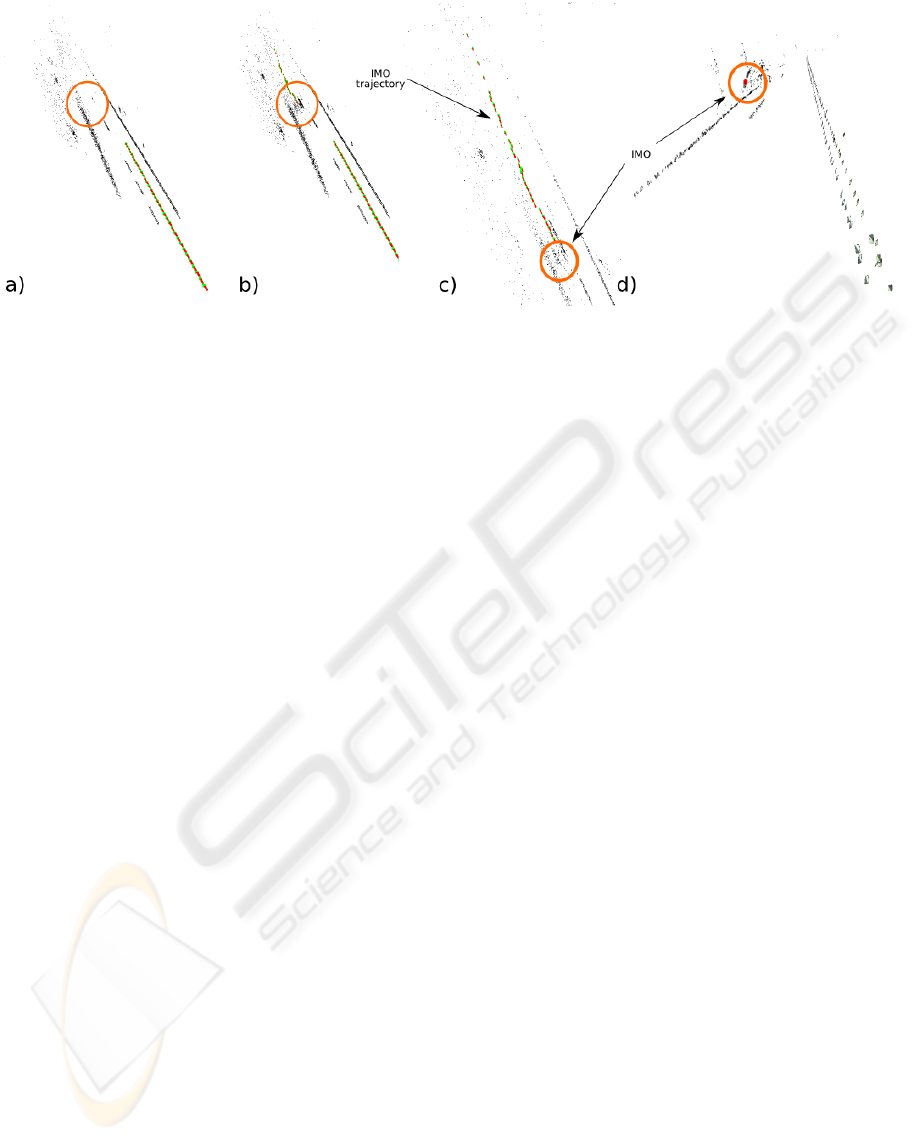
Figure 8: Illustration of a) the reconstructed road structure, b) and c) trajectories for the ego– and IMO–motion, and d) the
reconstructed 3D model of the car with the lane structure.
row.
In the IMO case, some 40 SIFT features are ex-
tracted from the image patches, and between 10 to
20 of them are reliably matched both across stereo
and time. Fig. 7 shows five of the detected and
tracked IMOs, taken from the two sequences T03 and
S06. Because this motion is computed visually, it ef-
fectively combines the vehicle’s egomotion with the
IMO’s actual motion. As can be seen the motion esti-
mates are qualitatively correct.
Fig 8 shows the reconstructed road for sequence
T03 and IMO #4, with trajectories (string of green
and red arrows) for both the egomotion and the IMO.
Fig 8a) shows only the road and the egomotion trajec-
tory. In Fig 8b) and c) show the road structure with
the IMOs and their trajectory. Fig 8d) shows the re-
constructed IMO and the reconstructed road structure.
As can be seen, by the combination of all three levels,
it is possible to give a qualitatively correct description
of the ego–motion, the road structure, the 3D move-
ment of the IMO as well as the relative position of the
IMO to the road structure.
4 CONCLUSIONS
We presented a three level architecture that is com-
posed of the following components: A dense, model
free, IMO detection mechanism; an attention mech-
anism; and a sparse, feature tracking, motion esti-
mation, and model building scheme. The combina-
tion of sparse and dense methods is shown to pro-
vide advantages in terms computational speed as well
as precision: The attention mechanism guided by the
low level allows for the processing of the motion at
the highest available resolution, while processing the
background at lower resolution. Finally, the system
provides not only detection of the IMOs, motion and
trajectories and a feature based model of the IMO’s
shape.
REFERENCES
Bar-Shalom, Y. (1978). Tracking methods in multitarget
environment. IEEE trans. on Automatic Control, AC-
23:618–626.
Bertozzi, M. and Broggi, A. (1998). Gold: A parallel real-
time stereo vision system for generic obstacle and lane
detection. IEEE TIP, 7(1):62–81.
Betke, M., Haritaoglu, E., and Davis, L. S. (2000). Real–
time multiple vehicle detection and tracking from a
moving vehicle. Machine Vision and Applications,
12:69–83.
Caputo, G. and Lombardi, L. (1995). Attention mechanisms
in computer vision systems. Int. Workshop on Com-
puter Architectures for Machine Perception.
Comaniciu, D., Ramesh, V., and Meer, P. (2003). Kernel–
based object tracking. IEEE TPAMI, 25(5):564–577.
Cox, I. J. (1992). A review of statistical data associa-
tion techniques for motion correspondence. IJCV,
10(1):53–66.
Dissanayake, P., Newman, P., Durrant-Whyte, H., Clark, S.,
and Csorba, M. (2001). A solution to the simultane-
ous localisation and mapping (SLAM) problem. IEEE
trans. in Robotics and Automation, 17(3):229–241.
Fawcett, T. (2006). An introduction to ROC analysis. Pat-
tern Recognition Letters, 27(8):861–874.
Fischler, R. and Bolles, M. (1981). Random sample consen-
sus: A paradigm for model fitting with applications to
image analysis and automated cartography. Comm. of
the ACM, 24(6):619–638.
Hoiem, D., Efros, A. A., and Hebert, M. (2007). Recovering
surface layout from an image. IJCV, 75(1):151–172.
Hoiem, D., Efros, A. A., and Hebert, M. (2008). Putting
objects in perspective. IJCV, 80(1):3–15.
A THREE-LEVEL ARCHITECTURE FOR MODEL-FREE DETECTION AND TRACKING OF INDEPENDENTLY
MOVING OBJECTS
243

Kalman, R. E. (1960). A new approach to linear filtering
and prediction problems. Jour. of Basic Engineering,
82-D:35–45.
Kr
¨
uger, N., Lappe, M., and W
¨
org
¨
otter, F. (2004). Bio-
logically motivated multi-modal processing of visual
primitives. AISB Jour., 1(5):417–427.
Leibe, B., Schindler, K., Cornelis, N., and van Gool, L.
(2008). Coupled object detection and tracking from
static cameras and moving vehicles. IEEE TPAMI,
30(10):1683–1698.
Lourakis, M., Argyros, A., and Orphanoudakis, S. (1998).
Independent 3d motion detection using residual paral-
lax normal flow fields. In ICCV, pages 1012–1017.
Lowe, D. (2004). Distinctive image features from scale-
invariant keypoints. IJCV, 1(1).
Montemerlo, M., Thrun, S., Koller, D., and Wegbreit, B.
(2002). FastSLAM: A factored solution to the simul-
taneous localization and mapping problem. In AAAI.
Pauwels, K. and Van Hulle, M. (2006). Optimal instanta-
neous rigid motion estimation insensitive to local min-
ima. CVIU, 104(1):77–86.
Pauwels, K. and Van Hulle, M. (2008). Realtime phase-
based optical flow on the gpu. In CVPR Workshop on
Computer Vision on the GPU.
Pauwels, K. and Van Hulle, M. (2009). Optic flow from
unstable sequences through local velocity constancy
maximization. IVC, 27(5):579–587.
Pilz, F., Pugeault, N., and Kr
¨
uger, N. (2009). Comparison
of point and line features and their combination for
rigid body motion estimation. Visual Motion Analysis,
Springer LNCS 5604.
Pugeault, N. (2008). Early Cognitive Vision: Feedback
Mechanisms for the Disambiguation of Early Visual
Representation. VDM Verlag Dr. M
¨
uller.
Reid, D. B. (1979). An algorithm for tracking multiple tar-
gets. IEEE trans. on Automatic Control, AC-24(6).
Rosenhahn, B., Kr
¨
uger, N., Rabsch, T., and Sommer, G.
(2001). Automatic tracking with a novel pose estima-
tion algorithm. Robot Vision.
Rushton, S., Bradshaw, M., and Warren, P. (2007). The pop
out of scene-relative object movement against retinal
motion due to self-movement. Cognition, 105(1):237–
245.
Sabatini, S., Gastaldi, G., Solari, F., Pauwels, K., Van Hulle,
M., Diaz, J., Ros, E., Pugeault, N., and Krueger, N.
(2007). Compact (and accurate) early vision process-
ing in the harmonic space. In VISAPP, pages 213–220.
Sawhney, H., Guo, Y., and Kumar, R. (2000). Independent
motion detection in 3d scenes. IEEE TPAMI, 22(10).
Thompson, W. B. and Pong, T. C. (1990). Detecting
moving-objects. IJCV, 4:39–57.
Thrun, S., Liu, Y., Koller, D., Ng, A., Ghahramani, Z., and
Durrant-Whyte, H. (2004). Simultaneous Localiza-
tion and Mapping with Sparse Extended Information
Filters. IJRR, 23(7–8):693–716.
VISAPP 2010 - International Conference on Computer Vision Theory and Applications
244
