
SYNTHESIS OF B
´
EZIER SURFACES ON THE GPU
R. Concheiro, M. Amor
Universidade da Coru
˜
na, Spain
M. B
´
oo
Universidade de Santiago de Compostela, Spain
Keywords:
B
´
ezier surfaces, GPU, Adaptive tessellation, Level of detail (LOD).
Abstract:
B
´
ezier surfaces are one of the most useful primitives employed for high quality modeling in CAD/CAM tools
and graphics software. Traditionally, the B
´
ezier representations are usually tessellated on the CPU (Central
Processing Unit) and the set of generated triangles is sent to the GPU (Graphic Processing Unit). The CPU-
GPU bus can become a bottleneck in this approach due to the large number of triangles generated for high
quality models. In this paper we present two proposals for synthesizing the B
´
ezier models directly in the
GPU. With this strategy the compact representation associated with the B
´
ezier models is sent to the GPU
where the rendering is performed. The first proposal is based on the exploitation of the vertex shader to
perform the tessellation. In this case a parametric map guides the computation of the final coordinates of
a set of virtual vertices. Our second proposal is based on the efficient exploitation of the geometry shader
capabilities to perform the tessellation in a direct way. Tests performed show that both proposals produce high
quality images and promising results for real time rendering of complex parametric models.
1 INTRODUCTION
NURBs (Non-Uniform rational B-splines) surfaces
(Piegl and Tiller, 1997) have been widely employed
in CAD/CAM tools and graphic applications due to
their capabilities for modeling complex geometries.
Together with the high quality associated with the
NURBS models, another advantage of the NURBS
representations is the compactness of the description
and, as a consequence, the low storage and transmis-
sion requirements.
Current GPUs (Graphic Processing Unit) are tri-
angle oriented and not designed for the direct render-
ing of parametric representations. Therefore, these
representations are usually tessellated into triangles in
the CPU (Central Processing Unit) before being sent
to GPU to be displayed. This strategy presents some
problems which diminishes system performance, for
example, the amount of information to be sent from
CPU to GPU or the increment in the storage require-
ments associated with the triangle mesh.
To synthesize parametric surfaces on the GPU the
tessellation of the models is directly realizing on the
GPU (Guthe et al., 2005; Dyken et al., 2009). In these
proposals the rendering process is performed per
patch (Guthe et al., 2005) or per set of patches accord-
ing to the required level of detail (Dyken et al., 2009).
In these applications the computational cost increases
with the number of patches due to the amount of syn-
chronous calls between CPU and GPU. Another tes-
sellation approach is presented in (Eisenacher et al.,
2009; Schwarz and Stamminger, 2009) where the tes-
sellation of bicubic B
´
ezier surfaces is performed fol-
lowing a GPGPU strategy (General-Purpose Compu-
tation on GPU).
Although the strategy is interesting, the program-
ming platform is in fact inadequate for advanced ren-
dering systems.
In this work we focus on the tessellation of B
´
ezier
surfaces on GPU. B
´
ezier surfaces are a particular case
of NURBs surfaces (Piegl and Tiller, 1997). B
´
ezier
representations are widely used because of their lower
complexity. Additionally the tessellation of NURBs
models is usually performed through their previous
conversion to B
´
ezier representations.
In this paper we present two approaches for B
´
ezier
110
Concheiro R., Amor M. and Bóo M. (2010).
SYNTHESIS OF BÉZIER SURFACES ON THE GPU.
In Proceedings of the International Conference on Computer Graphics Theory and Applications, pages 110-115
DOI: 10.5220/0002847201100115
Copyright
c
SciTePress

surfaces tessellation on the GPU. Our first proposal
consists of the utilization of a parametric map of vir-
tual vertices (Guthe et al., 2005) with an efficient
exploitation of the information stored on the GPU.
Specifically, we propose an adaptive technique that
permits the optimization of the memory usage of the
GPU to increase the data locality exploitation. This
strategy allows the minimization of draw calls and
the CPU-GPU communications.The second proposal
is based on the utilization of the geometry shader for
the generation of geometry in the GPU. This tech-
nique avoids the precomputation and storage of pre-
defined grids in the local memory as the tessellation
can be executed on-the-fly. Both proposals have been
tested under different GPU platforms. Good results in
terms of quality and timing requirements have been
obtained for both. As result of our analysis we con-
clude that the adequate exploitation of the GPU capa-
bilities is close to permit real time rendering of para-
metric models even for very complex scenes.
This paper is organized as follows:
In Section 2 a brief revision of tessellation options
on current GPUs are summarized. Then, in Section
3 our first proposal based on the efficient storage and
exploitation of the information with the vertex shader
is presented. In Section 4 the second proposal based
on the utilization of geometry shader is developed. In
Section 5 the proposals are evaluated and finally, in
Section 6 the main conclusions are highlighted.
2 TESSELLATION OPTIONS IN
CURRENT GRAPHICS CARDS
In this section, we briefly summarize the structure
of current GPUs and the available hardware options
for tessellation. The structure of the GPU accord-
ing to Direct3D10 (Blythe, 2006) consists of fixed-
function stages (Input Assembler, Rasterizer and Out-
put Merger) and three programmable stages (Vertex
Shader, Geometry Shader and Pixel Shader) whose
behavior is defined by a code. With the tessellation
procedure in mind, we will focus our analysis on the
programmable stages and the possibilities to imple-
ment a tessellation procedure on them.
The programmable vertex and pixel shaders can
not be employed for generating/destroying geometry
in a direct way and have no access to the information
associated with another neighboring primitives.
The geometry shader works with primitives
(point, line segment, or triangle) and the output num-
ber of primitives can be higher or lower than the input
number. Adjacent information is available so that for
each triangle the information of the three neighbor tri-
angles can be accessed. However, the main drawback
is the limitation of the number of output primitives
per invocation, as currently only 1024 32-bit values
can be output. The intermediate results processed by
the vertex shader or the geometry shader can be sent
either back to the pipeline through stream out, allow-
ing iterative processing, or can be sent directly to the
rasterization stage.
Recently, the introduction with DirectX 11 (Ni
and Casta
˜
no, 2009) a new tessellator unit permits the
tessellation on the GPU. However, this unit performs
a fixed and regular pattern.
But today the geometry shader is the only option
for the direct implementation of a free tessellation al-
gorithm.
Taking into account these options, our proposals
exploit two different alternatives for the tessellation.
The first one is based on the exploitation of the ver-
tex shader (VST, Vertex Shader Tessellation). In this
case, and due to the impossibility to generate geome-
try, the utilization of techniques based on virtual ver-
tices (Boubekeur and Schlick, 2005) is the key for
a multiresolution application. The second proposal
is based on the exploitation of the geometry shader
(GST, Geometry Shader Tessellation). In this case,
the tessellation of surface is performed in the geom-
etry shader. The resolution level can be selected on-
the-fly and the generated geometry can be fed back to
the standard pipeline through the stream out unit. In
next sections we describe in detail both proposals.
3 VERTEX SHADER
TESSELLATION (VST)
In this section we describe our proposal for the B
´
ezier
surfaces tessellation using the vertex shader. Our
method is based on the storage and efficient exploita-
tion of the information in the GPU. Specifically, our
proposal uses a regular grid of parametric coordi-
nates as the basis for the computation. The efficient
scheduling employed permits the efficient exploita-
tion of the information stored in the GPU reducing the
transmission requirements between CPU and GPU.
The representation of a B
´
ezier surface
Q(u,v), 0 ≤ u,v ≤ 1 is based on the utilization
of two parametric values defined in a normalized
interval [0, 1]. In our proposal the tessellation is per-
formed on the GPU and this implies the evaluation of
the surface equation Q(u,v) for different parametric
values (u, v). The resulting points are vertices that are
connected to build the triangles of the final mesh. For
reasons of clarity we work with a simple algorithm
that performs a uniform subdivision of the parametric
SYNTHESIS OF BE´ ZIER SURFACES ON THE GPU
111

space in the two dimensions. Specifically and for a
tessellation level l, 2
l+1
parametric values in each
dimension are considered. The grid of parametric
values P
l
to be evaluated are:
P
l
=
(u
1
,v
1
) ··· (u
1
,v
2
l+1
)
(u
2
,v
1
) ··· (u
2
,v
2
l+1
)
.
.
.
.
.
.
.
.
.
(u
2
l+1
,v
1
) ··· (u
2
l+1
,v
2
l+1
)
(1)
where
u
i
,v
i
=
i − 1
2
l+1
− 1
,i ∈ {1,·· · , 2
l+1
}
For a resolution level l, the grid of parametric val-
ues to be evaluated P
l
is made up of 2
l+1
× 2
l+1
sam-
ples. The resolution level to be applied to each B
´
ezier
surface is selected by the application taking into ac-
count different factors (screen space error, model
complexity,...). Taking this into account, a system of
L grids of parametric values for the different resolu-
tion levels {P
1
,P
2
,··· ,P
L
} can be computed a priori,
L being the highest resolution level. These grids are
computed and stored in the GPU to be selected and
employed for the different surfaces of the model.
However, the utilization of a single system of grids
limits the speed of the application. If an unique sys-
tem of grids stored in memory is accessed by all sur-
faces in the scene a sequential procedure is forced.
This means that for each frame there are as many
Draw Primitive calls as surfaces N
S
, so the perfor-
mance decreases due to the amount of calls. There-
fore, the amount of synchronizations, N
DP
, by frame
is N
DP
= N
S
. As only a surface is computed per Draw
Primitive call, GPU parallelism is not exploited. Ad-
ditionally, a large amount of synchronous calls de-
crease the performance because a Draw Primitive is a
slow operation. Therefore in our proposal we use sev-
eral copies of the system of grids of parametric values
to process more surfaces per draw call. That is, sev-
eral copies of {P
1
,P
2
,··· ,P
L
} are used. The utiliza-
tion of different copies of the grid systems permits
the simultaneous evaluation of several models with
the consequent increment in the processing speed.
To evaluate the number of surfaces that can be pro-
cessed per Draw Primitive call the storage require-
ments of the application have to be evaluated.
VST performs N
DP
draw calls, processing and ren-
dering N
d
surfaces per call: N
DP
=
N
S
N
d
with 1 ≤ N
d
≤ N
S
. Then, the required amount of
memory is
M =
L
∑
l=1
M
P
l
× N
d
+ M
[B
s
]
× N
S
where M
P
l
is the memory requirements for the grid
of resolution level l, P
l
, and N
S
is the number of
surfaces in the scene. M
[B
s
]
includes the amount of
memory used for the control points of each surface.
For a (n, n)-degree surface this amount is, M
[B
s
]
=
3 × (n + 1) × (n + 1).
The desirable framework is storing all data on the
GPU memory and performing an unique draw call.
But when the storage requirements exceeds a given
value of capacity, the performance decreases. Tak-
ing this into account, we have developed an adaptive
technique whereby to get an optimum application in
terms of speed, the following transmission and stor-
age requirements have to be verified:
1. The data transfer between CPU and GPU has to
be minimized. In our proposal the information re-
quired (parametric grids and control points of the
surfaces) is sent once to the GPU. The information
is efficiently stored and re-employed for optimum
performance.
2. The storage requirements associated with the
grids of parametric values should not exceed
the global memory capabilities. Specifically, in
our application the grids are stored in a vertex
buffer but exceeding the recommended capabil-
ities would result in limitations for other uti-
lizations and could affect the resource swapping.
As a result the following condition has to be
verified:
∑
L
l=1
M
P
l
× N
d
< per · M
GPU
M
GPU
being the GPU global memory size and per
a percentage value that depends on each GPU.
3. In our application and due to the global memory
latency the control points [B
s
] of the surfaces are
stored in the texture memory. This memory is
cached so if there is a cache miss the informa-
tion is obtained from global memory with a delay.
Therefore, the storage of the control points asso-
ciated to the B
´
ezier surfaces to be processed per
draw call should not exceed the capabilities of the
texture memory. That is, M
[B
s
]
× N
d
< M
T
being
M
T
the texture memory size.
4. The number of draw calls (N
DP
) should be mini-
mized due to their fixed-cost overhead (Akenine-
M
¨
uller et al., 2008). The basic idea of our batch-
ing strategy is combining many small transfers
into a large one to optimize the data communi-
cation procedure.
The analysis of the storage requirements and rec-
ommended number of draw calls according to our
tests is included in the results section.
GRAPP 2010 - International Conference on Computer Graphics Theory and Applications
112

4 GEOMETRY SHADER
TESSELLATION (GST)
In this section, our second proposal is included. This
approach is based on the exploitation of the geome-
try shader for the B
´
ezier surfaces tessellation (GST).
The objective is exploiting the geometry shader capa-
bilities for geometry generation. This, in contrast to
the vertex shader proposal, permits the generation of
geometry without requiring the utilization of a virtual
vertices strategy. Therefore, the GPU memory does
not limit the level of resolution per surface.
The key idea of our GST proposal is the on-the-
fly computation of the P
l
values for each input sur-
face. As a consequence, no pre-computed grids are
employed and the storage requirements are reduced
since only the control points of the surfaces are re-
quired. Current versions of the geometry shader per-
mits the generation of 1024 32-bit elements per in-
put primitive. This, in our implementation, limits the
number of triangles to be generated per B
´
ezier surface
and, in consequence, the maximum resolution level to
be generated. Specifically, the maximum resolution
level allowed is l = 3, that is, 2
4
× 2
4
triangles can be
generated. Our method obtains a higher level of detail
with an iterative execution of the geometry shader for
each surface. This approach is possible as the geom-
etry shader output can be stored in output stream and
feedback as input for the rendering pipeline. How-
ever, the inherent timing costs associated with the it-
erative procedures makes the reduction of the number
of iterations to be performed important. The objec-
tive of our proposal is to reduce this number of itera-
tions through an efficient method to increase the high-
est level of detail that can be managed per iteration.
The key idea of the GST proposal for increasing
the resolution level is partitioning the parametric map
in zones and the parallel evaluation of these zones in
the geometry shader. That is, the P
l
grid (see Equation
1) with 2
l+1
× 2
l+1
parametric values is partitioned
and the corresponding parametric values groups pro-
cessed in parallel in the geometry shader. Consider-
ing groups of m × m parametric values the P
l
matrix
of values can be rewritten as a system of submatrices:
P
l
=
P
l
[1,1]
··· P
l
[1,Nz
v
]
.
.
.
.
.
.
.
.
.
P
l
[Nz
u
,1]
··· P
l
[Nz
u
,Nz
v
]
(2)
Nz
u
and Nz
v
are the number of zones in u and v
directions, respectively. Thus is,
Nz
u
=
2
l+1
m
; Nz
v
=
2
l+1
m
In our proposal two geometry shader kernels are
devoted to two tasks: zones identification and tessel-
lation per zone.
The first task of the algorithm is the parametric
grid partitioning into zones. As indicated in Equation
2 the P
l
matrix is partitioned into a set of submatri-
ces P
l
[i, j], with i = 1,··· ,Nz
u
and j = 1, · · · ,Nz
v
.
In our approach the first shader makes the paramet-
ric map partitioning through the identification of the
first element of each submatrix, (u
(i·m)+1
,v
( j·m)+1)
).
Once this value is identified, the remaining paramet-
ric values can be generated with simple incremen-
tal operations. As a result, the first shader generates
four values per zone [s,u
(i·m)+1
,v
( j·m)+1
,t], where s is
the surface index and t indicates the iteration num-
ber. Due to the geometry shader limitations (only
1024 32-bit data can be generated per input primitive)
up to 1024/4 = 256 zones can be processed in each
step of the iterative algorithm. The second shader per-
forms the evaluation of the B
´
ezier surface correspond-
ing to each zone. In consequence the resolution level
that can be obtained with our proposal per iteration is
2
4
· m × 2
4
· m, with m = 4, l
GS
= 5.
The second shader of the algorithm performs the
surface evaluation for the points assigned to each
zone. The zones will be managed by the geometry
shader as isolated input primitives, the vertices lo-
cated in the border among zones are evaluated more
than once. This permits the avoidance of cracks be-
tween contiguous zones. To avoid cracks between
neighbor zones the vertices in the border between two
zones have to be computed for both zones. Conse-
quently, the matrices are of size (m + 1) × (m + 1)
with an overlap of elements between matrices with
consecutive indices.
5 EXPERIMENTAL RESULTS
In this section we present the results of the evaluation
of our VST and GST proposals.
We ran our implementations on an Intel Core 2 2.4
GHz with 2 GB of RAM and on two different GPUS:
Nvidia GeForce 9800 GTX (Nvidia) with DirectX 10
Microsoft’s HLSL and ATI Radeon 5870 (ATI) with
DirectX 11 Microsoft’s HLSL.
We evaluated our proposals with different scenes
comprising replicated versions of a small set of mod-
els. The models (Teacup, Teapot and Elephant) em-
ployed are depicted in Figure 1 with different reso-
lution levels. The final images have a screen resolu-
tion of 1280 × 1024 pixels. Table 1 includes the re-
sults obtained for 16 of these scenes, denoted as S
i
,
with i = 1,··· ,16. Column N
s
includes the number of
SYNTHESIS OF BE´ ZIER SURFACES ON THE GPU
113
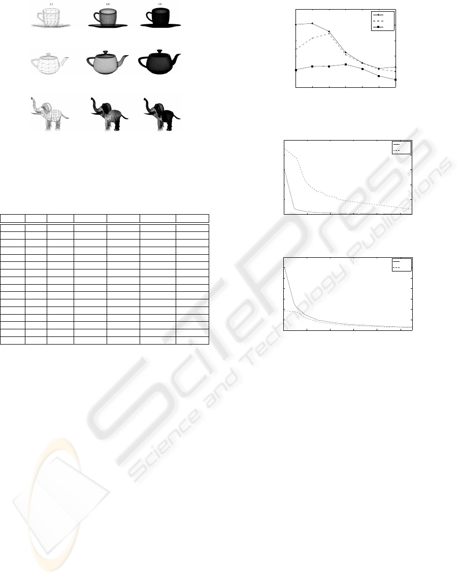
L1 L4
L6
(a)
(b)
(c)
Figure 1: Models employed in the test scenes (a) Teacup (b)
Teapot (c) Elephant.
Table 1: Number of triangles generated (in K) for each
scene with L = 4 and L = 6.
Scene N
s
N
1
T
N
4
T
N
4
T
Adpt. N
6
T
N
6
T
Adpt.
S
1
26 0.46 48.80 25.49 819.05 432.66
S
2
32 0.56 60.06 34.39 1008.06 554.98
S
3
260 4.57 488.01 254.86 8190.51 3815.56
S
4
320 5.63 600.62 343.95 10080.63 5206.89
S
5
520 9.14 976.02 509.72 16381.02 6935.26
S
6
640 11.25 1201.25 687.90 20161.25 9454.31
S
7
780 13.71 1465.02 764.59 24571.52 9259.56
S
8
811 14.26 1522.21 1241.23 25548.08 14923.50
S
9
960 16.88 1801.88 1031.84 30241.88 12856.10
S
10
1040 18.28 1952.03 1019.45 32762.03 10801.40
S
11
1280 22.50 2402.50 1375.79 40322.50 15142.10
S
12
1300 22.85 2440.04 1274.31 40952.54 11495.80
S
13
1600 28.13 3003.12 1719.74 50403.13 16525.70
S
14
2600 45.70 4880.08 2548.62 81905.08 38865.80
S
15
3200 56.25 6006.25 3439.48 100806.25 30826.25
S
16
8110 142.56 15222.09 12421.30 255480.84 55340.50
B
´
ezier surfaces, while column N
1
T
includes the num-
ber of triangles generated for the coarsest level of de-
tail; i.e., L = 1. Columns N
4
T
and N
6
T
include the num-
ber of triangles generated with L = 4 and L = 6 for a
non-adaptive tessellation. Columns N
4
T
Adpt. and N
6
T
Adpt. show the number of generated triangles on av-
erage for an adaptive tessellation proposal with L = 4
and L = 6; i.e., when the resolution level of each sur-
face is up to 4 or 6 respectively. In this case, the res-
olution of each surface is selected on the basis of its
position in the scene with a varied set of viewpoints.
Note that complex scenes with a high number of sur-
faces were used.
First, and for the VST proposal, the number of
draw calls N
DP
were analyzed. As an example of
our analysis, Figure 2 shows the frames per second
for scene S
5
for different N
DP
and L values consider-
ing Nvidia. A similar behavior was obtained for all
the scenes tested. As can be observed in the figure,
the number N
DP
has a strong influence on the perfor-
mance. For example, the obtained speedup is 1.42
with L = 5 for N
DP
= 4, and up to 1.31 with L = 6 for
N
DP
= 8. The good performance in terms of frames
per second is due to the reduction of global mem-
1 2 4 8 16 32 64
0
20
40
60
80
100
NDP
frames per second (fps)
L=4
L=5
L=6
Figure 2: VST proposal variant N
DP
for S
5
with L = 4, L = 5
and L = 6.
0 10 20 30 40 50
0
50
100
150
200
250
N
T
1
(K)
frames per second (fps)
GST
VST
(a)
0 10 20 30 40 50
0
500
1000
1500
2000
2500
3000
3500
N
T
1
(K)
frames per second (fps)
GST
VST
(b)
Figure 3: VST and GST for L = 4 (a) Nvidia GeForce 9800
GTX and (b) ATI Radeon 5870.
ory accesses and the efficient utilization of the tex-
ture memory. In summary, the satisfactory results are
associated with the data locality exploitation and the
scheduling strategy employed. For larger N
DP
values
this trend changes due to the cost overhead of each
draw call. With respect to the dependence with the L
value, for larger L values the best frames per second
values are obtained for larger N
DP
values. Accord-
ing to Wloka’s rule (Akenine-M
¨
uller et al., 2008), is
due to the larger number of polygons per surface and
the rasterization costs which makes the standard GPU
pipeline the bottleneck of the application.
Finally, we conducted a detailed analysis of the ef-
ficiency of our tessellation methods. Figure 3 depicts
the performance for L = 4 with two GPUs. VST and
GST proposals obtain a good performance in terms
of FPS, allowing real-time adaptive tessellation, even
for a high number of triangles. For example, for scene
S
5
with 9.14 K input triangles, 113.8 fps for the VST
proposal and 10.04 fps for the GST proposal are ob-
GRAPP 2010 - International Conference on Computer Graphics Theory and Applications
114

0 10 20 30 40 50
0
500
1000
1500
2000
2500
3000
3500
N
T
1
(K)
frames per second (fps)
GST
Tessellator
Figure 4: Comparative for GST and Tessellation unit on a
Radeon 5870.
tained with the Nvidia. With the ATI, 606.36 and
742.64 fps are obtained with the VST and GST pro-
posals, respectively. In this case, as indicated in Ta-
ble 1, the number of triangles generated is 509.72 K
with an adaptive approach. Moreover, in the Nvidia
the performance of the GST method is inferior to the
performance achieved with the VST method. While
in ATI using DirectX 11 the result is opposite. The
differences in performance would seem to be due to
the improvement in the utilization of geometry shader
output as input to the vertex shader. Specifically, for
L = 4 the utilization of two stages is necessary to ob-
tain the desired resolution level.
On the other hand, comparisons in terms of fps
with other proposals are analyzed. Moreover, with re-
spect to traditional algorithms of tessellation on the
GPU (Guthe et al., 2005), our two proposals have
achieved better performance in all cases and in both
architectures; for example, the scene S
5
of this pro-
posal is 4.05 fps on Nvidia. Finally, Figure 4 shows a
comparative between our GST approach and the uti-
lization of the tessellation unit (Microsoft, 2009) on
the ATI, where, in any case, our proposal obtains a
better performance.
6 CONCLUSIONS
In this paper we have presented two proposals for the
tessellation of B
´
ezier surfaces on the GPU. The first
method, VST, is based on the utilization of virtual ver-
tices strategy and a system of multi-resolution para-
metric maps. The utilization of this system of maps
to evaluate the final coordinates of the virtual vertices
allows the processing of multiple surfaces in parallel.
Additionally, to exploit the data locality and to reduce
the number of global memory accesses, an analysis
of the optimum number of surfaces to be processed in
parallel was performed.
With respect to the second method, GST, it is
based on the exploitation of the geometry shader as
a primitive generator. Due to the current limitations
of the shader in terms of number of primitives gener-
ated per input primitive, our proposal is based on the
utilization of a smaller primitive, a parametric map
section.
As a result of our analysis we conclude that cur-
rent and future graphics cards will become an ad-
equate platform for parametric surfaces tessellation.
We have obtained very good results in terms of timing
requirements for both proposals on complex scenes.
ACKNOWLEDGEMENTS
This work has been partially suppported by the Min-
istery of Science and Innovation of Spain under con-
tract TIN 2007-67537-C03 and Xunta de Galicia un-
der the contract 08TIC001206PR.
REFERENCES
Akenine-M
¨
uller, T., Haines, E., and Hoffman, N. (2008).
Real-Time Rendering. A. K. Peters, Ltd, third edition.
Blythe, D. (2006). The Direct3D 10 System. ACM Trans.
Graph., 25(3):724–734.
Boubekeur, T. and Schlick, C. (2005). Generic Mesh Ee-
finement on GPU. In HWWS ’05: Proceedings of
the ACM SIGGRAPH/EUROGRAPHICS conference
on Graphics hardware, pages 99–104.
Dyken, C., M., R., and Seland, J. (2009). Semi-uniform
Adaptive Patch Tessellation. Computer Graphics Fo-
rum, 28(8):2255–2263.
Eisenacher, C., Meyer, Q., and Loop, C. (2009). Real-time
view-dependent rendering of parametric surfaces. In
I3D ’09: Proceedings of the 2009 symposium on Inter-
active 3D graphics and games, pages 137–143, New
York, NY, USA. ACM.
Guthe, M., Bal
´
azs, A., and Klein, R. (2005). GPU-Based
Trimming and Tessellation of NURBS and T-Spline
Surfaces. ACM Trans. Graph., 24(3):1016–1023.
Microsoft (2009). Directx sample browser (august 2009).
http://www.microsoft.com/.
Ni, T. and Casta
˜
no, I. (2009). Efficient Substitues for Sub-
division Surfaces. Exhibition Tech. SIGGRAPH’09
Course Notes, 2009.
Piegl, L. and Tiller, W. (1997). The NURBS book. Springer.
Schwarz, M. and Stamminger, M. (2009). Fast GPU-based
adaptive tessellation with cuda. Computer Graphics
Forum, 28(2):365–374.
SYNTHESIS OF BE´ ZIER SURFACES ON THE GPU
115
