
BUBBLEWORLD BUILDER
3D Modeling using Two-touch and Sketch Interaction
Amit Joshi, Glen Robertson, Burkhard C. Wünsche and Beryl Plimmer
University of Auckland, New Zealand
Keywords: Two-touch Interaction, 3D Modeling, Radial Basis Functions, Sketch-interface, Iso-surfaces.
Abstract: Commercial 3D modeling applications tend to be difficult and time consuming to use due to complex
interfaces and functionality. In this paper we present a simple and intuitive interface for modeling “blobby”
3D objects using touch input. Objects are defined by sketching and modifying contours of cross-sectional
slices. Two-touch interactions are used to zoom, rotate and slice the object. The resulting application allows
rapid creation of 3D models and looks promising for medical imaging applications. A drawback is that
intuitiveness depends on a user’s mental abilities such as 3D vision and the ability to develop a mental
model and compare it with visual data.
1 INTRODUCTION
Three dimensional (3D) modeling is becoming
increasingly valuable in fields such as entertainment,
medicine and engineering. Despite this, modern 3D
modeling applications remain difficult to use
without extensive training. In order to make 3D
modeling more accessible to inexperienced users we
decided to investigate recent developments in multi-
touch and sketch technologies and apply them to
provide a more intuitive interface for 3D design.
One source of the complexity of current 3D
modeling tools is the mouse and keyboard paradigm.
The standard mouse provides bidirectional motion
whereas input information in three directions is
required to design 3D models. To compensate for
this, existing applications provide a range of
operations to specify this third dimension. This tends
to result in complex interfaces with many buttons,
menus and views of the object model, making them
unintuitive as they lack analogy to real world
interactions. Consequently it takes a significant
effort to attain proficiency with them, and pen and
paper is still preferable for early design stages.
New multi-touch screens surpass traditional
touch screens by registering more than one point of
contact at a time. We used a NextWindow
(http://www.
nextwindow.com) touch screen which provided two
simultaneous touch points. The relative motion of
fingers and touch area recognition provides
increased degrees of freedom to enable a variety of
touch actions. Additionally it gives a greater sense of
directness because the user puts their fingers directly
on the item of interest. These properties can be used
to provide input that is more analogous to real world
actions than the traditional mouse and keyboard.
Sketching, or digital ink, is another recent area of
development and is `the digital analogy to pen and
paper drawings. The motion of a user’s finger or
stylus is captured and converted to a series of on
screen strokes. This is useful for rapidly developing
ideas because the user is less constrained by
application semantics and tends to alter ideas more
often (Black, 1990). Considering that free hand
sketches are a common part of the 3D design process
it may be useful to integrate sketching directly into
the interactive modeling process. And because
sketching can be performed with a touch interaction
it can be combined with multi-touch systems.
Using touch-based techniques we designed and
implemented an interface, where 3D objects can be
modified by editing cross-sectional slices. A new 3D
surface is then rendered from these slices using
radial basis interpolation. By placing more
functionality into the touch actions rather than
buttons and menus we reduce the user’s mental load
and simplify the interface. And by providing design
flexibility with the slice-based approach our solution
is suitable for simple rapid prototyping and design
applications.
116
Joshi A., Robertson G., Wuensche B. and Plimmer B. (2010).
BUBBLEWORLD BUILDER - 3D Modeling using Two-touch and Sketch Interaction.
In Proceedings of the International Conference on Computer Graphics Theory and Applications, pages 116-122
DOI: 10.5220/0002849501160122
Copyright
c
SciTePress

2 RELATED WORK
In the Origami Simulator (Chang et al, 2009) a
virtual piece of paper can be moved and folded using
two-touch interactions analogous to the art of paper
folding known as Origami. Results from user
evaluations on this application suggest that multi-
touch interaction can be intuitive, enjoyable and
useful for interacting with 3D environments. It was
from this concept we decided to explore a more
general 3D modeling interaction.
Previous sketch based tools for 3D modeling
have used rapid and rough sketches with simple
interfaces for fast modeling. For example, in Teddy
(Igarashi et al, 1999) sketched 2D shapes are inflated
to produce 3D shapes – it is suggested that about ten
minutes of practice is required to be able to make
fairly interesting shapes. However editing of the
resulting object is limited.
Alternative input devices have used bimanual
interaction to increase the available degrees of
freedom for 3D environment interaction. In 3-Draw
(Sachs et al, 1991) a remote control-like device is
held in each hand. The 3D motion of the devices
provides 3D input to generate models. This
transcends the limitations of 2D motion of mice,
however, is still limited by 2D display. Virtual
surface models are also bimanually controlled in the
Polygon Surface Design (Shaw & Greeen, 1994)
tool. These tools require special devices which are
less readily available than multi-touch screens.
In the Profile Driven Sketch tool (Bartolo et al,
2008) the profile sketch of an object is annotated
with cross-section views at various points which are
used to generate a wireframe model. However direct
interactin with the wireframe is not provided.
Commercial modeling tools such as AutoCAD
(Autodesk Inc., 2010) provide lofting algorithms
that interpolate surfaces through cross sections.
These rely on fixed position mouse slices.
3 DESIGN
This section covers the early design phase of our
project. It describes the requirements of the project
and key factors considered for the solution design.
The focus of this research was to explore the use
of multi-touch and sketch to develop a simpler and
more intuitive interface for 3D modeling. In the first
stage of our research we created a set of
requirements for the application based on
observations, evaluation of previous work, and
informal interviews. The key usability requirements
derived were a minimal interface and intuitiveness.
The interface should have fewer items on screen,
which is achieved by transferring functionality from
buttons and menus into touch gestures. This allows
more room for model display. For the application to
be intuitive the touch actions must be analogous to
real life actions.
In terms of functional requirements, the key
factors are 2D to 3D mapping, flexibility, simplicity
and shape predictability. Considering the touch
screen provides two spatial dimensions it is
necessary to have a mechanism to provide input for
a third spatial dimension yet have the flexibility to
model a range of objects. Lastly the application
should accurately infer the shape the user wants to
create.
3.1 Solution Design
From the above requirements we designed a cross-
section based solution where the user manipulates
the shape by editing slices of the shape. Cross
sections are a common 3D design approach. They
can be used to provide 2D to 3D mapping because
the orientation of the slice plane (the plane on which
the cross-section rests) and the slice profile (the
profile seen on the cross-section) provides three
spatial dimensions of information.
With a cross-section approach the lofting method
must be chosen: how will a 3D shape be generated
from the cross-sections? The three methods
considered were Morphing, Edge-Minimisation and
Radial Basis Function Interpolation; the later was
choosen as the best balance between flexibility,
simplicity and shape predictability. It would enable a
greater range of objects to be modeled because
unlike the other two, it naturally deals with cross-
sections in arbitrary orientations. And because it
produces curved surfaces based on the idea of
bending energy minimization it better reflects the
curvature of natural objects. As a drawback the
method does not allow straight edges or corners.
However, we felt that users would be more
interested in modeling objects with curves rather
than flat faces. And although we hypothesized that
the other methods may be more understandable, the
flexibility provided by it was more important.
Other investigated design methods were
discarded because they did not meet the
requirements. For example, direct manipulation of
vertices, edges and faces is a common operation,
however, would pose greater challenges in terms of
2D to 3D mapping despite providing more
BUBBLEWORLD BUILDER - 3D Modeling using Two-touch and Sketch Interaction
117
flexibility. Silhouettes are similar to cross-sections
and have been successfully employed for modeling
(Igarashi et al, 1999), but impose restrictions on the
types of shapes. Domain specific solutions can be
very elegant (McCord et al, 2008), but are unsuitable
for general modeling tasks.
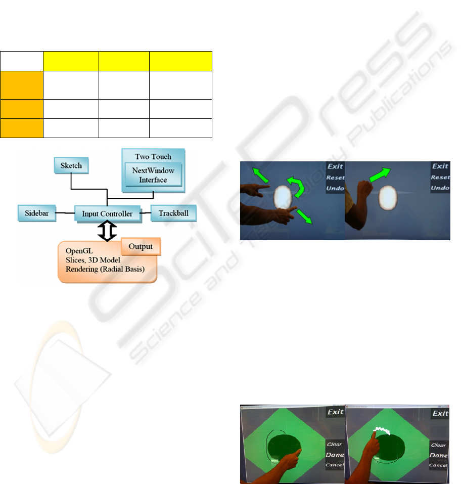
Our application is implemented in C# and uses
the OpenTk framework for OpenGL and the
Microsoft Ink API. The system architecture is shown
in Figure 1. The Multi-Touch component manages
an interface to the NextWindow dynamic link
library.
Table 1: Comparison of proposed modeling methods.
2D to 3D
Mapping
Flexibility Simplicity
Cross-
Section
Based
Easy High Expected High
Vertex
Control
Difficult High Low
Domain
Specific
Easy Low High
Figure 1: System architecture of our application.
4 INTERACTION
To create a model the user specifies cross-sectional
profiles that lie in arbitrary orientations in a 3D
space. There are two interaction modes. In object
mode two-touch actions are used to position the
model. In sketch mode the user draws the profile
shape from which a 3D surface is interpolated with a
radial basis function interpolation.
The object is shown in an off-white colour and
the slice planes are shown in pale grey (Figure 2). A
selected slice is green to visually indicate that is is
editable (Figure 3).
The design process occurs in three steps. First
the object is positioned as required by rotation and
zooming. Next a slice plane is specified to define the
area to be edited. Lastly the slice profile is drawn
and the new shape of the object generated. This
process is repeated to extend and edit the shape as
the user sees fit.
4.1 Interaction Gestures
In object mode two-touch actions are used to zoom
and rotate the object and create slices. These are
analogous to real life object interactions. A single
touch gesture across the screen rotates the object like
a spinning globe. Two contact points moved closer
together or further apart zoom the object out and in
respectively, like stretching a rubber band. One
touch, moving around a stationary touch, rotates and
zooms at the same time.
An area touch, formed by a knuckle or three
finger contact, dragged across the screen creates a
slice. The cross-section plane lies along this line
perpendicular to the screen Once cut, the object
rotates to put the slice flat on to the screen for
sketching. Figure 2b shows a slicing action between
two points in the direction of the arrow.
Figure 2: Object actions: a) Zooming and rotation b)
Slicing.
Once in slice mode the user can sketch and erase
the intended profile (Figure 3). Dragging a finger
across the screen sketches a black line along the
finger path. Scribbling quickly over existing lines
erases them (analogous to using an eraser on pencil).
Once erasing begins, any sketched line that the
finger passes over is removed. When the new cross-
section is finished the ‘Done’ button commits the
sketch to the slice and renders the altered object in
object mode.
Figure 3: Sketch actions. a) drawing b) erasing.
GRAPP 2010 - International Conference on Computer Graphics Theory and Applications
118
5 RADIAL BASIS FUNCTION
INTERPOLATION
The 3D model corresponding to the sketched slices
is obtained by creating a 3D density field f(x) which
has the property that f(p)=0 for every point p on a
sketched contour, f(p)>0 for every point p inside a
sketched contour, and f(p)<0 for every point p
outside a sketched contour. The 3D surface of the
object defined by these contours is then given as all
points x in the 3D domain where f(x)=0. We extract
this iso-surface using a Marching Cube Algorithm
(Lorensen et al, 1987).
The function f(x) is constructed by generating
sample points which are on a contour, outside a
contour, and inside a contour. We then perform a
radial basis function interpolation such that f(x)=0, -
1 and +1 for points on, outside and inside a contour,
respectively. Using a function f(x) of the form below
results in a visually pleasing surface with minimal
bending energy (Carr et al, 2001):
∑∑
==
+=
m
j
jjii
n
i
i
xpxdRxf
10
)())(()(
βα
(1)
Here
)(
i
rR
is the basis function
iiii
rrrrR log**)( =
(2)
By inserting the n sample points with the conditions
that f(x)=0, -1 and +1 (for sample points on, outside
and inside a contour) we get the linear system of
equations
⎟
⎟
⎠
⎞
⎜
⎜
⎝
⎛
=
⎟
⎟
⎠
⎞
⎜
⎜
⎝
⎛
0
f
b
a
M
(3)
where
a
and
b
are vectors with the
α
and
β
coefficients of each equation and f is a vector with
the field values at the sample points (0, -1 or 1). The
unknown coefficients are found by solving the linear
system of equations using an LU decomposition or a
more efficient solver as described in (Carr et al,
2001).
Sample points on the contour are easily obtained
by sampling the underlying parametric curve with an
arclength parameterization. Alternatively a curvature
based measure can be used (not implemented) to
create more sample points in regions of high
curvature.
Points inside and outside of a contour are created
by taking normals to the cross-section shape
vertices. We define that the inside (outside) areas of
the cross-section contours on each slice form the
inside (outside) of the resulting 3D object. In order
to get a well behaved surface we need to find a
sufficient number of sample points on the inside and
outside. We calculate these points using the vertices
defining a contour.
Let us take a vertex P on an arbitrary slice. P has
two adjacent vertices P
1
and P
2
. From these three
vertices we form two vectors V
1
and V
2
.
V
1
= P
1
– P (4)
V
2
= P
2
– P (5)
Next we calculate two sample points, one inside
the shape and one outside the shape, as follows.
V
in
= P
1
+ P
2
(6)
V
out
= P – V
in
(7)
We give V
in
the field value 1 and V
out
the field
value -1. Positive field values occur inside the shape
and negative field values occur outside the shape.
This approach assumes convex contours,
however we perform an extra operation to account
for concave curves. A point inclusion algorithm is
used to ensure the correct selection of V
in
and V
out
.
The algorithm is run over V
in
to check that a point is
actually inside the shape. This is done by firing a ray
from outside the shape to V
in
. The number edges
passed to reach the point is counted. If the number is
odd the point is considered to be inside. Otherwise,
V
in
and V
out
are swapped.
The algorithm is applied to each sample point on
a contour so that we get an equal number of sample
points inside, outside, and on the surface of the
object to be modelled. Note that this algorithm fails
if the distance between two parallel lines is less than
the length of the normalized normal – in that case
the outside point or one contour might lie inside
another contour.
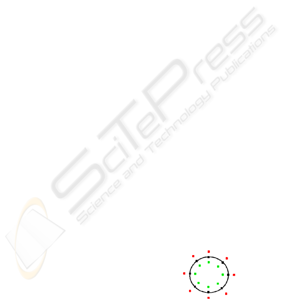
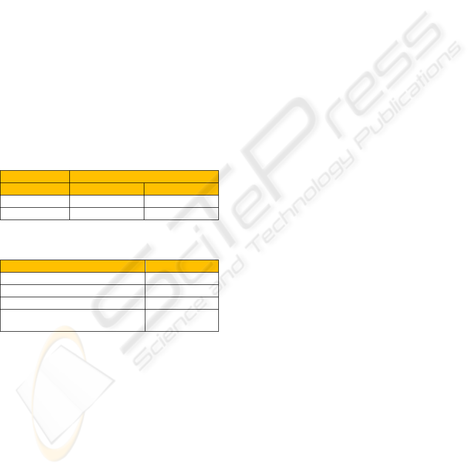
Figure 4 shows a cross-section with generated
sample points. The black dots have field values of 0,
the green dots field values of 1 and red dots of field
values -1.
Figure 4: Density field of sample points of a slice.
BUBBLEWORLD BUILDER - 3D Modeling using Two-touch and Sketch Interaction
119
There are two significant limitations to the
modeling system. First, certain slice combinations
are contradictory and hence result in no surface
being constructed. Second, slices that are too far
apart do not result in a surface that flows between
both slices and instead two separate surfaces are
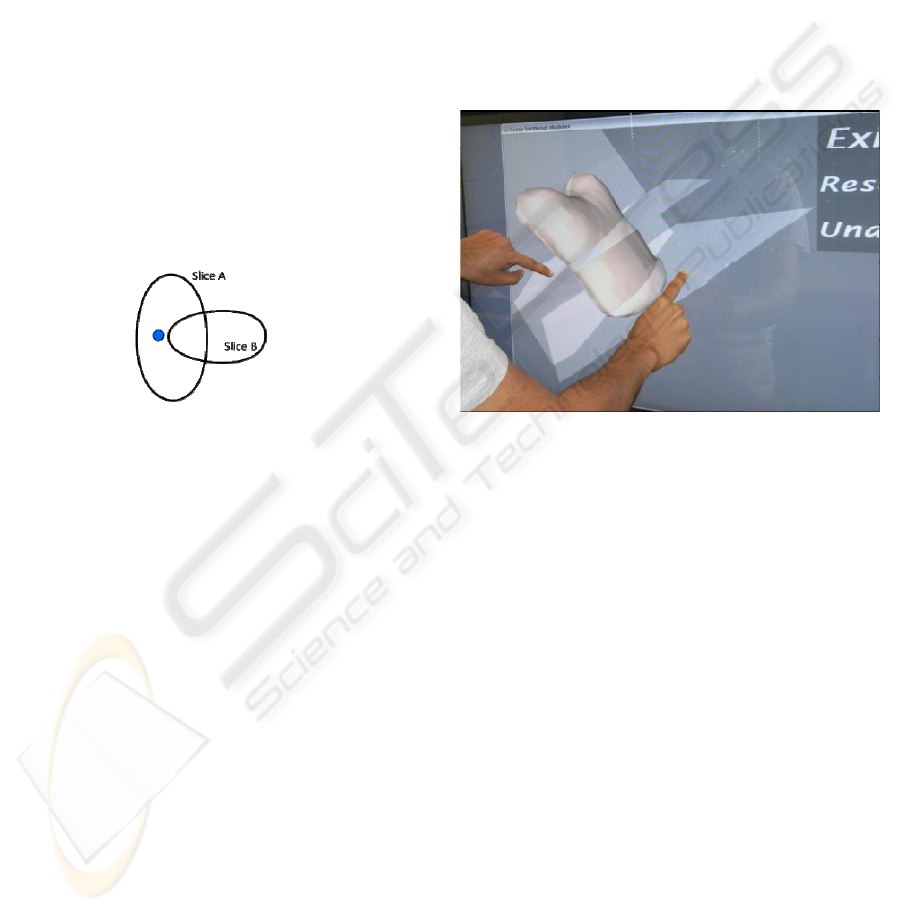
formed for the contour of each slice.
The contradictory slices include overlapping and
intersecting slices as illustrated in figure 5. In this
example the blue point is considered by slice A to be
inside but by slice B to be outside the shape. Since
the density field function f(x) cannot have two
different values for the same point, no solution exists
and consequently no object surface is constructed
and displayed. In this situation the last valid state of
the object is restored. Getting around this problem
requires a testing of consistency of sketched
contours and appropriate warning messages.
Alternatively conflicting contours could be
automatically adjusted (contours must be disjoint or
correspond where slices intersect).
Figure 5: The blue point has an ambiguous density field
value since it is inside the contour of slice A, and outside
the contour of slice B.
The second problem is due to the bending energy
minimization nature of the radial basis function. If
two slices are a sufficient distance apart bending
energy is minimized by producing two separate
surfaces rather than one large one. The problem
could be resolved by adding interpolated slices, but
this contradicts the nature of the radial basis function
interpolation. Furthermore, it is not clear under what
circumstances a user would expect one combined or
two separate surfaces. Both of these limitations
reduce predictability of the surface and hence its
intuitiveness and usability.
6 RESULTS
We used our application to create a variety of simple
blobby objects (for example figure 6). While the
sketch input is efficient, the control of the shape is
limited. The range of possible shapes is limited
because we don’t allow nested contours on a slice in
order to construct hollow objects
6.1 User Evaluation
A user evaluation was performed in order to
determine the efficacy of Bubbleworld. The factors
of interest were the naturalness of the touch actions,
the ability of users to model objects using the cross-
section approach and a comparison to mouse
interaction for the same process. The evaluation was
conducted by observing users performing modeling
tasks and recording qualitative feedback (from post-
task surveys) and quantitative measurements (time
taken to perform tasks). The details of the study are
presented below and an interpretation is provided in
section 7.
Figure 6: Result of using two horizontal and a vertical
contour.
Ten software engineering students who had
experience with 3D environments (mostly from
computer games), and were familiar with 3D
modeling tools participated in the study. A few
students frequently used two-touch iPhones and
most had previously used a multi-touch screen (at
least a few times). Their experience with technical
drawings varied from ‘a couple of times’ to
‘frequently’. The participants could be considered
very technologically capable with little 3D modeling
and multi-touch experience.
The participants were individually shown
Bubbleworld running on a NextWindow touch
screen and given basic training. This included
demonstrating and teaching them all the main
operations (Zooming, Rotating, Slicing and
Sketching). They were then given two minutes of
free time with the application to familiarize
themselves with the actions and screen.
The participants were then asked to perform four
simple tasks while we video recorded them. The
tasks were zooming the object, rotating the object,
elongating the object and widening the bottom of the
GRAPP 2010 - International Conference on Computer Graphics Theory and Applications
120
object. This was to observe their ability to
understand the actions. Next they were asked to
create a banana shape. This was to observe their
ability to design with the application. Finally they
were asked to repeat the process using the mouse
instead of the touch screen. At the end of the
procedure they filled out a questionnaire.
After all the participants had completed the
procedure we extracted the time to complete the
banana task from the video recordings. The time is
recorded as the time between the user understanding
the task and when they were happy with their design
(Table 3). On average, user’s performed the task
faster with the mouse than the with the touch screen.
This is partially explained by the fact that once
user’s had performed the task with the touch screen,
they knew what to do hence could more quickly
complete it with the mouse. An additional factor
would be the difficulties in using this particular
screen. This is discussed further in the next section.
Results for questions from the survey are presented
in Table 3.
Table 2: Task completion times.
Time Taken (min.sec)
Touch Screen Mouse
Mean
1.54 1.48
Range
2.42 3.30
Table 3: Survey results on seven-level Likert scale (-3 =
strongly disagree to 3=strongly agree).
Question Mean Result
Interaction was enjoyable
2.3
Interaction felt natural
0.2
Rendering was predictable
-0.1
Cross-sections are useful for 3D
design
1.8
7 DISCUSSION
The goal of our research was to develop an intuitive
interface for 3D environments. The evaluation
survey results suggest that users found the interface
enjoyable and easy to understand. This suggests a
level of simplicity or intuitiveness of the
interactions hence making them easy to remember.
Additionally the sense of directness of touching the
object may have added to the enjoyability compared
to the traditional mouse method. Interestingly only a
moderate level of naturalness was suggested by the
survey despite our attempts to design real-world
analogous actions. This may relate to the problem of
2D input. The actions are still not closely enough
related to holding and manipulating a real 3D object
in one’s hands. The main problem is the flat screen
being the interaction medium. Another reason for
this may be limitations of the hardware, e.g.
sensitivity and friction, which reduced the sense of
naturalness.
The second goal of our research was to provide a
simple interface which doesn’t have the steep
learning curve encountered with traditional 3D
modeling tools. Our implementation contains at
most four buttons on the screen at any time and the
user is still able to perform a fair amount of
manipulation using it. The minimalistic interface has
enabled us to free screen space for displaying the
modeled object and because of the easy interaction
we found that users do not require the multiple
views usually encountered in traditional tools. The
interface could be minimized further by using
gestures or even speech recognition.
Although we considered the input actions to be
user friendly, the user study showed that the contour
interpolation was not as intuitive as expected. Users
were surprised when distant slices did not join
together or certain slices could not be rendered.
Even for valid user input the predictability was
moderate. It seems that users need some experience
or a mental model (“soap bubbles”) of how the
radial basis function interpolation affects objects.
Indeed, one user suggested in the survey feedback
that intuition would increase with continuing usage.
Although we did not carry out a formal
comparative study we were curious about how
usability would change with mouse input instead of
using a touch screen. Participants commented that
they were more used to the mouse which helped
them to use it well. This suggests that touch screens
may need to reach a greater level of ubiquity in
order to reach their full potential in terms of
effective and natural user input.
The spatial reasoning of users had an impact on
their design skills. There appeared to be little
difficulty in performing basic operations involving a
few slices such as extrusions, however our
observations were that modeling becomes
increasingly difficult the more slices are used. This
is due to the difficulty of visualizing how a surface
can flow through many slices. A way around this
could be to create multiple localized surfaces rather
than one global surface for all the slices. This would
provide greater control of the shape and improve
predictability. Objects could be created from
positioning together many smaller ones which is one
main feature of traditional modeling tools.
BUBBLEWORLD BUILDER - 3D Modeling using Two-touch and Sketch Interaction
121

8 CONCLUSIONS & FUTURE
WORK
Existing commercial 3D modeling applications are
complex to use and hence significant training is
required before users reach proficiency. In response
to this we have designed and implemented a simpler
3D modeling application which utilizes two-touch
and sketch techniques. Our solution was enjoyable
for users and can be used to quickly design a variety
of objects. However, limitations were imposed by
the underlying mathematical model and users’
ability to create 3D mental models and match them
to visual input.
The results of our research indicate that the
concept of 3D modeling based on touch and sketch
input is promising, but more work needs to be done
to make it more effective and natural. One major
obstacle is the lack of 3D vision of many users and
might only be completely overcome with the
emergence of 3D displays and consumer level 3D
gesture recognition.
Even with the above limitations there are already
a lot of useful applications available. We are in
particular interested in medical imaging applications
where slice input is natural (x-rays, CT and MRI
data sets) and where users (medical professionals)
have exceptional 3D vision and 3D mental
capacities. We are currently working on tools for
user-assisted object segmentation using touch input.
REFERENCES
Autodesk Inc. (2010). AutoCAD. www.autocad.com,
accessed January 2010, San Rafael, CA.
Bartolo, A., Farrugia, P., Camilleri, K., and Borg, J.
(2008). A Profile-driven Sketching Interface for Pen-
and-Paper Sketches, VL/HCC Workshop: Sketch Tools
for Diagramming, Herrsching am Ammersee,
Germany.
Black, A. (1990). Visible planning on paper and on screen:
The impact of working medium on decision-making
by novice graphic designers, Behaviour and
information technology, 9(4):283-296.
Chang, S. H., Lachlan, S., Plimmer, B., Wuensche, B.
(2009). Origami Simulator: A Multi-Touch
Experience, Proceedings of the 27th international
conference extended abstracts on Human factors in
computing systems, ACM, New York, pages 3889-
3894.
Igarashi, T., Matsuoka, S., and Tanaka, H. (1999). Teddy:
A Sketching Interface for 3D Freeform Design,
Proceedings of the 26th annual conference on
Computer graphics and interactive techniques, ACM,
New York, 409-416.
Lorensen, W. E. and Cline, H. E. (1987). Marching cubes:
A high resolution 3D surface construction algorithm.
SIGGRAPH Comput. Graph. 21(4):163-169.
McCord, G., Wuensche, B., Plimmer, B., Gilbert, G.,
Hirsch, C. (2008). A Pen and Paper Metaphor for
Orchid Modeling, Proceedings of the 3rd
International Conference on Computer Graphics
Theory and Applications (GRAPP 2008), 22-25
January 2008, Funchal, Madeira, Portugal, pages 119-
124.
Sachs, E., Roberts, A., Stoops, D. (1991). 3-Draw: A Tool
for Designing 3D Shapes, IEEE Computer Graphics
and Applications, 11(6): 18-26.
Shaw, C., Green, M. (1994). Two Handed Polygonal
Surface Design, Proceedings of the 7th Annual ACM
symposium on User Interface Software and
Technology (UIST ’94), ACM, New York, pages 205-
212
GRAPP 2010 - International Conference on Computer Graphics Theory and Applications
122
