ROBUST DETECTION AND IDENTIFICATION OF PARTIALLY
OCCLUDED CIRCULAR MARKERS
Johannes Koehler, Alain Pagani and Didier Stricker
DFKI GmbH, Trippstadter Strasse 122, 67663 Kaiserslautern, Germany
Keywords:
Circular markers, Ellipse fitting, Marker design, Robustness.
Abstract:
In this paper we present a pipeline for the robust detection of partially occluded circular markers. Compared
to square markers, occluded circular tags can be tracked in a more robust way, since the camera pose is in
this case computed from the whole contour instead of only the four corners. We introduce a new ellipse
detection technique based on a constrained RANSAC algorithm and pre-ellipse fit outlier removal to detect
tag candidates with damaged borders. Digital codes are used to identify the actual markers afterwards, since
correlation based marker identification approaches are not capable of handling occlusion. The key to error
detection and correction is a suitable Reed Solomon code together with a proper code layout on the marker.
We show that markers covered up to 30% can be detected, our tracker moreover has a very low risk of false
positive marker detection.
1 INTRODUCTION
In the context of computer vision and augmented re-
ality, markers can be used to provide easily detectable
visual cues for e.g. robot navigation (Sattar et al.,
2007), indoor tracking (Naimark and Foxlin, 2002),
marking important or interesting points in 2D/3D and
defining coordinate systems for placing augmenta-
tions (Fiala, 2004). The tags should be detectable
within a certain distance to the camera and even in
a simple, “tidy” scenario an object can quickly get
between the camera and the tag, covering parts of it.
Successful detection under partial occlusion is there-
fore an important use case (Figure 1). Most of the
existing marker systems either use square- and/or cir-
cular markers. We believe that circular tags provide
a higher robustness to occlusion, since the camera
pose used for accessing the marker content can be
computed from the whole elliptic contour. In case of
square markers, the pose computation relies only on
the four vertices. The tag can not be detected any-
more as soon as a whole edge is covered, whereas
the ellipse-shaped contour resulting from a circle still
contains enough information to obtain a good pose
estimation. The ellipse resulting from the perspective
projection of the marker however yields two possi-
ble poses only one of which is correct. We use the
error detection capabilities of the marker code to re-
trieve the correct pose, since the code cannot be read
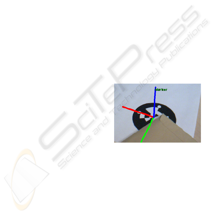
Figure 1: The successful identification of an occluded
marker is visualized by rendering the coordinate frame it
defines.
correctly from the wrong pose for most angles. Cir-
cular markers additionally need special features for
determining their orientation, which is not naturally
induced by the tag’s shape as it is the case with square
markers. We address the degenerated ellipse contours
resulting from occlusion with a RANSAC-based el-
lipse fitting technique that allows for successful fitting
even if the ellipse’s contour contains large damages.
We assume that a total amount of 255 markers is
sufficient for most AR applications and use a non-
redundant digital ID composed of 8 bits on our mark-
ers together with a suitable Reed Solomon (“RS” in
the following) code (Moon, 2005) for error correc-
tion and a CRC code for error detection, inspired by
387
Koehler J., Pagani A. and Stricker D. (2010).
ROBUST DETECTION AND IDENTIFICATION OF PARTIALLY OCCLUDED CIRCULAR MARKERS.
In Proceedings of the International Conference on Computer Vision Theory and Applications, pages 387-392
DOI: 10.5220/0002850603870392
Copyright
c
SciTePress

ARTag (Fiala, 2004). Since RS codes are symbol ori-
ented polynomial codes, we recommend a construc-
tion of the code over a small field, such that symbol-
chunks on the marker do not contain too many bits.
We also optimize the code to maximize the error cor-
rection capabilities.
The remainder of this paper is organized as fol-
lows: Section 2 reviews marker tracking and ellipse
fitting approaches. Sections 3 and 4 cover error tol-
erant ellipse fitting and digital marker identification,
the essentials of our processing pipeline. We finally
conclude with an outlook to future work.
2 RELATED WORK
Robustness characteristics for a marker tracker have
already been discussed in the context of the ARTag
square marker system (Fiala, 2004): It should pro-
vide low false positive/ negative detection rates as
well as not confuse the markers with each other. It
was pointed out that correlation based marker track-
ing systems like the popular ARToolkit (Kato and Bil-
inghurst, 2000) will not perform well in these areas,
therefore ARTag made use of digital codes. Correla-
tion based trackers are also not able to handle occlu-
sions robustly, because the “fiducialness” of an ob-
served ellipse is a threshold decision and the correla-
tion measure cannot be used to identify and correct
read errors. While ARTag performs well concern-
ing the detection- and confusion rates, the used dig-
ital code however is only capable of correcting two
bit errors out of 36 bits, which prohibits robust detec-
tion under larger occlusions. Other tracking systems
also do not address the problem properly. The precise
error correction capabilities of CyberCode where not
mentioned in (Rekimoto and Ayatsuka, 2000), so we
assume they are negligible. The tracker developed by
(Naimark and Foxlin, 2002) has no read error protec-
tion. In (Sattar et al., 2007) possible protection meth-
ods are suggested but the developed system does not
attempt to handle occlusions as well.
Our ellipse fitting technique is composed of 3
other methods. (Cai et al., 2004) use a RANSAC
based approach which computes a test model from
5 random contour points. They introduced the fit-
ting factor for deciding if the model fits the data well.
(Song and Wang, 2007) reduced the amount of con-
tour points to 3 which decreases the amount of needed
iterations. Both approaches however did not make use
of an error tolerance as it is common in RANSAC. We
found out that the fitting factor is occasionally high
for a poor fit when the points are chosen randomly
and solved this problem using a separation idea found
in (Zhang and Liu, 2005). Other ellipse fitting tech-
niques are either too slow (genetic algorithms, e.g.
(Yao et al., 2004)) or can not cope with defects to a
desired extend (optimization based approaches, e.g.
(Fitzgibbon et al., 1999)).
3 ELLIPSE DETECTION
Ellipses found in an image are the first indicator for
the presence of a circular marker. We first detect
closed contours in the thresholded, binary input im-
age, which serve as a region of interest (ROI) and
narrow the search scope (remark: These ROIs do not
necessarily need to be closed, in fact we delete cer-
tain parts from them). Our ellipse detection method
applied to each of the found contours is based on the
method of (Song and Wang, 2007). Their algorithm
roughly performs the following steps:
For each input contour do:
1. Select 3 contour points P
1
, P
2
, P
3
.
2. Compute a tangent T
i
at P
i
using a least squares
fit of a line to the contour points found within a
5x5-raster around P
i
.
3. Compute the potential ellipse center C from the
tangents.
4. Compute an ellipse E using C and P
i
.
5. Accept E if its fitting factor F is adequate.
We found several problems in this approach. First,
no error tolerance was used during the point hit test
which slows down the computation. We use a cross-
shaped mask allowing an error of 2 pixels in each pos-
itive and negative x/y direction.
Second, a 5x5 raster for tangent computation can
cause tangent distortions when outliers are captured
by the raster. Since our input contours are sequenced,
connected pixels, we can use the previous and suc-
ceeding pixels with respect to an index for tangent
computation for higher robustness.
Third, Ellipses fitting the contour poorly can nev-
ertheless score a high fitting factor. This results from
the fact, that the model (test ellipse) is compared
against the data (input contour) (refer to (Cai et al.,
2004) for details) and not vice versa as it is usually
done in a RANSAC algorithm. While sparing the
costly computation of the geometric distance of ev-
ery contour pixel to the test ellipse (see (Forsyth and
Ponce, 2003), p.338), this enforces only local fitting
in the area covered by the test ellipse. When the ran-
domly chosen tangent indices are close to each other,
the resulting test ellipses are often stretched and small
VISAPP 2010 - International Conference on Computer Vision Theory and Applications
388
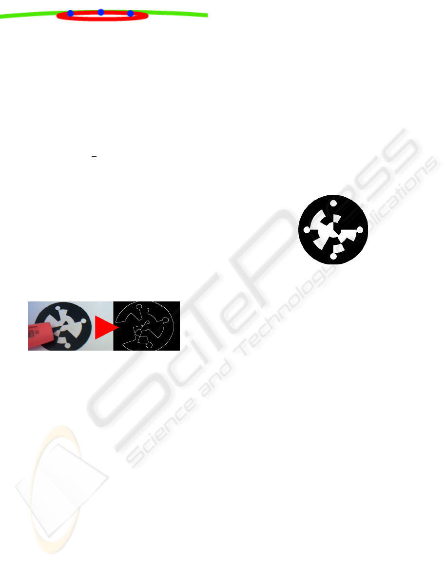
Figure 2: Green: part of the correct ellipse, blue: P
i
, red:
derived model evaluated in a RANSAC-iteration. It scores
a high fitting factor but does not fit the contour well.
and therefore can produce a high fitting factor (Figure
2.
To resolve this problem, we use the tangent sepa-
ration idea mentioned in (Zhang and Liu, 2005). We
enforce it in our approach with the evenly distributed
tangent (EDT)-constraint:
P
i
= P
i−1
+ ((
1
3
+ x) · cs) mod cs (1)
Where x ∈ [−0.1..0.1] is chosen randomly, cs is the
size of the input contour and P
i
, i ∈ {2, 3} are point
indices referring to the input pixel array. P
1
Is chosen
randomly. This assures an appropriate size of the test
ellipse.
Our goal is to detect occluded markers. In this
scenario the ellipse-shaped contour resulting from the
marker border will be broken. When applying a con-
trast enhancement to the input image, the occlusions
cause outlier parts in the form of convexity defects
in most cases (Figure 3). To prevent the choice of
Figure 3: Broken contour caused by occlusion.
tangent indices from outlier parts we remove these
defects from the contours. The direct least squares
method of (Fitzgibbon et al., 1999) is used to obtain
the final ellipses from from the consensus sets.
4 MARKER IDENTIFICATION
Those Ellipses observed in an image that did not orig-
inate from a marker must be excluded according to
the data found in their interior. To uniformly access
this data we hypothesize 2 possible camera poses, fol-
lowing (Chen et al., 2004). The distinction of the 2
poses is described later in this section. We chose a
marker identification based upon a digital code, since
this provides higher robustness compared to a cor-
relation based identification (Fiala, 2004). Read er-
rors can also be corrected, which is desired in case
of occlusions. Our markers carry 32 bits on 3 rings,
12 bits on the 2 outer- and 8 bits on the inner ring.
The reasoning for this layout is described at the end
of this section. To uniformly access these bins the
marker must first be properly oriented, respectively
the unknown camera rotation around the normal vec-
tor at the marker’s center must be computed. While a
square naturally induces 4 possible orientations, a cir-
cular marker needs special features for this. We there-
fore placed 4 spots on the outer marker border to ob-
tain 4 possible orientations(Figure 4). The symmetry
of these points guarantees that the rotation can be de-
termined even when other bright spots where found,
which is the case under occlusion. The correct among
the 4 possible rotations is determined by the decoding
properties of the bit sequence read at the respective
rotation. Only a single sequence must be allowed to
correctly decode. This idea originates from ARTag
(Fiala, 2004).
Figure 4: One of our new, digital markers.
Thus our processing steps are similar to ARTag:
Read 4 permutations, correct errors (RS stage), accept
the code word which passes the CRC check (CRC
stage). Because our goal is to find markers under
occlusion, the error correction abilities of the code
must be significantly higher. To achieve this we use a
long FEC- (a Reed Solomon (RS) in our case) and a
short CRC code, inversely to ARTag. This is possible
since we found that about 55% of all permutations
scramble the code word such that the RS code can
not recover it. It is discarded after the RS-stage. The
CRC-code distinguishes only between the remaining
ambiguities and is variable with respect to this objec-
tive. Since it cannot be computed analytically (Rice
et al., 2004), testing revealed that using the genera-
tor polynomial 0x8D (CRC-8-CCITT, (Moon, 2005)),
no other than the 0-codeword must be excluded for
ambiguities. We moreover assume a marker will not
carry more than 60 bits and thus construct primitive
RS codes over GF(16) = GF(2
4
) = GF(q
m
). The
RS code words then have a maximal symbol length of
n = q
m
− 1 = 15 with 4 bits per symbol. Our FEC-
redundancy length is 16 bits = 4 symbols. With stan-
dard decoding 2 symbols = 8 bits can be corrected.
In order to obtain valid permutations of the code
and therewith predictable decoding results, a bin
count divisible by 4 is necessary for each ring as il-
lustrated in Figure 5. When this is not the case, in-
valid bins are sampled and we can not be sure of the
ROBUST DETECTION AND IDENTIFICATION OF PARTIALLY OCCLUDED CIRCULAR MARKERS
389
obtained value. For these reasons the final code used
on our markers is 32 bits long, composed of an 8 bit
non-redundant ID, an 8 bit CRC code and a 16 bit RS
code, stored in 3 rings with 12 bits (outer rings) and 8
bits (innermost ring) (Figure 4). ARTag markers use
a 36 bit code with 10 bit ID, 16 bit CRC code and 10
bit FEC code.
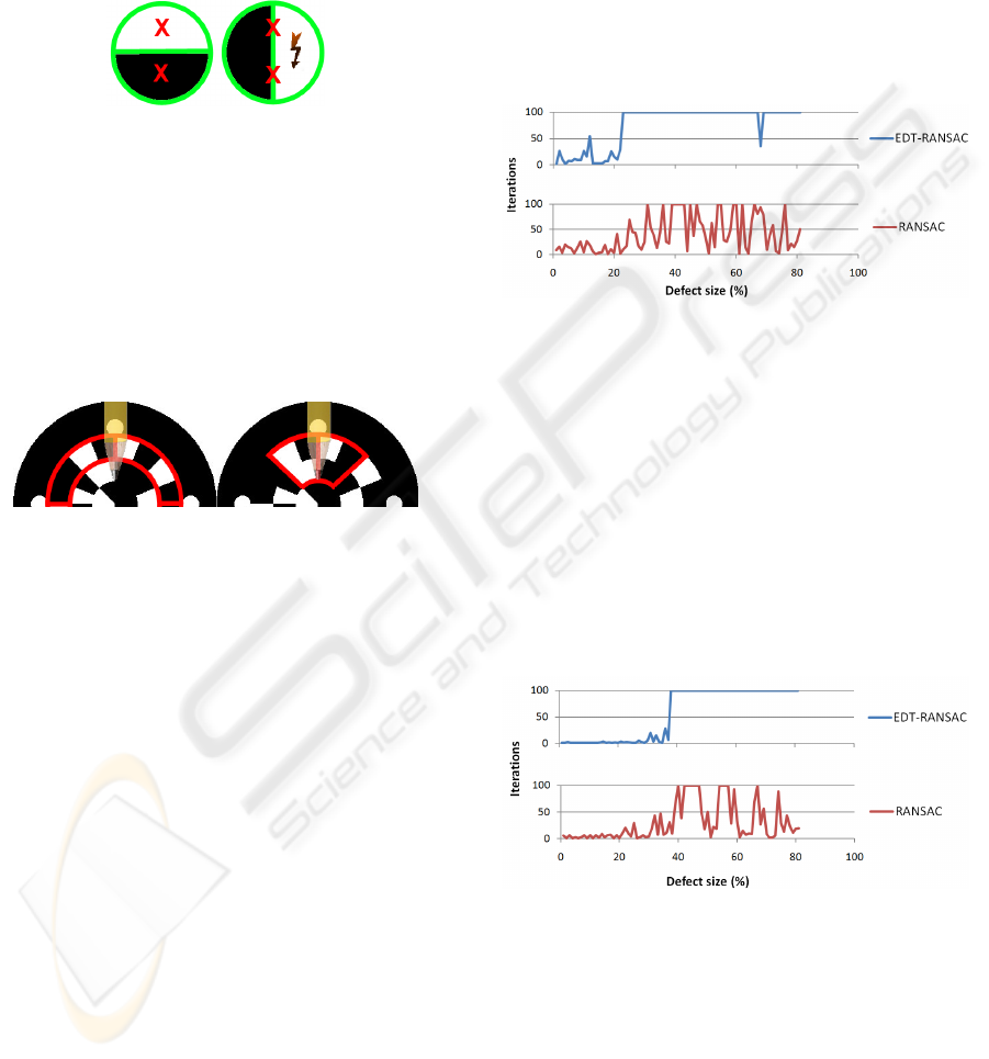
Figure 5: Exemplary innermost code ring, 2 bins. When
rotated by 90
◦
the result of the sampling is unclear - the
value might oscillate between black and white due to small
errors in the pose estimation.
The symbols must be placed on the marker such
that they fit to occluding objects well (Figure 6). We
therefore distribute the first 6 symbols of a code word
(= the first 24 bits) to the outer rings as seen in Figure
6 (right) and the remaining 2 symbols (= 8 bit) on the
innermost code ring.
Figure 6: Left: bad layout (2 symbols), recovery not possi-
ble. Right: good layout (2 symbols), recovery possible.
After successful identification we use the read er-
ror information to distinguish between the 2 pose es-
timations. We moreover use composites consisting of
2 coplanar markers or 3 markers in different planes.
The a priori information of the planes the markers lie
in can be used to recompute the camera pose after suc-
cessful marker identification. For 2 markers we com-
plete the approach that yielded the initial estimation
(Chen et al., 2004). For 3 markers in different planes
we use the approach found in (Kannala et al., 2006).
5 RESULTS
5.1 Ellipse Detection
We examined a series of intact ellipses with axis sizes
from 150:150 to 10:150 pixels. Each ellipse was fitted
with a pure random choice of points for tangent com-
putation and our EDT-constraint, 100 times each. The
ellipses were always successfully detected. Our EDT-
constrained algorithm needs an average of 1.2-1.7 it-
erations per ellipse compared to an average of 3.0-5.1
iterations of the unconstrained RANSAC algorithm.
Both algorithms handle intact ellipses well, the EDT-
constraint shows out to be slightly better. The graph
depicted in Figure 7 gives a first insight in how the al-
gorithm performs in the presence of defects. A grow-
ing defect is added to an ellipse with axis sizes of 75
and 150 pixels. The defect is not removed from the
detected contour. The algorithm stops trying to detect
the ellipse after 100 iterations, so an amount of 100 it-
erations corresponds to a failed detection. The fitting
factor is set to accept defects up to 40%.
Figure 7: Fitting of an ellipse (axis sizes: 75 and 150 pixel)
with a growing defect that is not removed.
We can see that neither the EDT-constrained nor a
pure random choice of tangent candidate points pro-
duces reliable fits. If the defects are removed how-
ever, EDT-RANSAC performs as expected (Figure 8),
the ellipse is not detected anymore at a defect size of
40% and a fairly low amount of iterations was needed.
With a pure random choice however, RANSAC still
detects an ellipse after the defect grew bigger than
40% although the demanded fitting factor can not be
scored anymore. This behavior results from the prob-
lem described in Section 3 and is not desired.
Figure 8: Fitting of an ellipse (axis sizes: 75 and 150 pixel)
with a growing defect that is removed, the fitting factor al-
lows a defect of up to 40%. Note the predictable behavior
of the EDT-constrained RANSAC in contrast to the false fits
detected by the previous RANSAC after the defect is larger
than 40%.
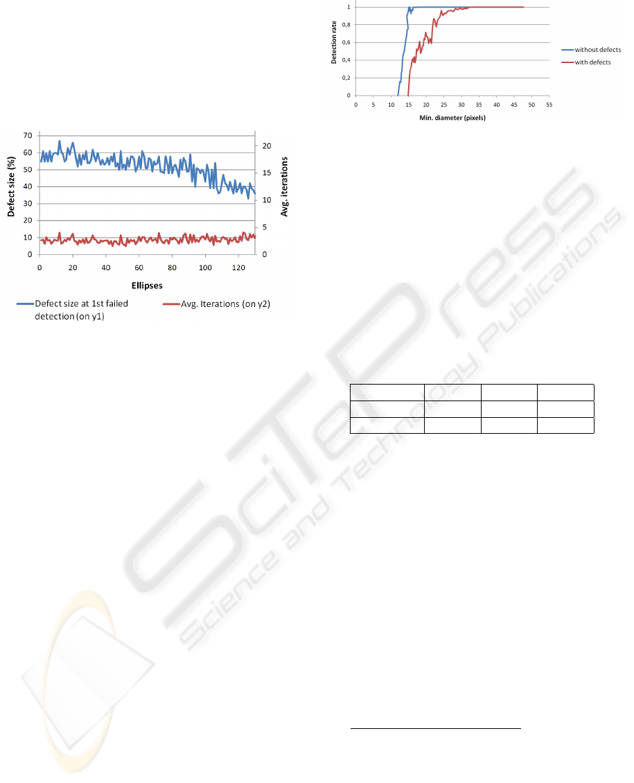
Figure 9 shows the maximal defect size that still
yields a successful detection with a feasible amount
of 15 iterations for a series of ellipses with axis sizes
from 150:150 to 20:150 pixels. The fitting factor is
set to allow a total defect of 85% for this experi-
VISAPP 2010 - International Conference on Computer Vision Theory and Applications
390
ment. When a consensus set was successfully com-
puted from a test ellipse whose axes differed by more
than 5% from the known correct ellipse the search is
considered as failed (in this case the estimated ellipse
would not fit to the contour). When no consensus set
was found after 15 iterations the search is also con-
sidered as failed. The results are shown in Figure 9.
This result shows that using defect removal, our al-
Figure 9: Maximal defect that could not be detected any-
more using 15 iterations (blue); Average iterations until first
failed detection (red).
gorithm can detect ellipses with large defects of 50%
and higher with a fairly low amount of iterations. As a
comparison the original P-RANSAC algorithm (Song
and Wang, 2007) was used with an amount of 35 itera-
tions to successfully recover ellipses in (Kaewapichai
and Kaewtrakulpong, 2008). Compared to this we re-
quire only 40% of iterations to obtain good fits.
5.2 Marker Identification
In this section we present the detection rate of our
marker tracker and the risk of a false positive marker
detection.
The graphs in Figure 10 illustrate the detection
rate of our marker tracker, which measures the min-
imal detectable pattern size. 9 different markers are
filmed by a webcam (Microsoft LiveCam VC-6000
1.0) in top view at various distances with a resolu-
tion of 640x480. For each distance, the number of
detected markers is recorded for a total amount of 20
frames. Division by the expected 180 markers then
yields the detection rate. The rate will be plotted as
function of minimal marker diameter inside the im-
age. This experiment was accomplished for 9 intact
as well as 9 partially covered markers (Figure 10).
With both intact and occluded markers we can score
a very good detection rate. In case of intact markers
the graph has a steep ascend from no to constant de-
tection between 12 and 17 pixels. When all of the 9
markers are partially occluded we obtain a first initial
Figure 10: Detection rate for intact and covered markers.
detection at a tag size of 15 pixel and constant detec-
tion at a size of 32 pixel, this means damaged tags
need to be approximately twice as big. The detection
rates for intact markers of ARTag and ARToolkit are
taken from (Fiala, 2004), p.32-35 for several camera
types. The tag-size intervals from a first initial- to
constant detection are found in Table 1. Although dif-
Table 1: Marker size intervals from initial to constant de-
tection for ARTag and ARToolkit. A: Greyscale PGR Drag-
onfly 640x480, B: Color PGR Dragonfly 640x480, C: In-
tel Pro 640x480 webcam. “+” in case of ARToolkit means
the value can be higher, depending on the confidence factor
(c.f.) used. Refer to (Fiala, 2004) for more details.
- A B C
ARTag 11-16 15-20 13-25
ARToolkit 10-30+ 10-55+ 15-26+
ferent camera types were used, it is obvious that the
detection rate of our markers can compete with these
results well. In case of intact markers we can score
almost the same detection rate with our webcam as
ARTag with the high-quality PGR Dragonfly camera.
When the markers are occluded, our detection rate is
slightly worse but still close to non-occluded ARTag
markers and much better than ARToolkit, which is not
able to handle occlusions of any kind.
The risk for a false positive marker detection
is 0.0039% (Fiala, 2005) in case of ARTag. With
higher error correction capabilities this risk grows
since more false words are mapped to a correct code
word. The risk in case of our markers is computed
with equation 2.
(1 +
8
1
· n +
8
2
· n
2
) · (4 ·255)
2
32
= 0.153% (2)
where n =
∑
4
i=1
4
i
= 15 are the possibilities to cor-
rupt a 4 bit symbol. Although almost 40 times higher
than in ARTag, this risk is still fairly low. In fact even
a much higher risk does not yet pose a problem since
the actual probability for a marker pattern to appear
in a scene by chance is not involved in these consid-
erations.
ROBUST DETECTION AND IDENTIFICATION OF PARTIALLY OCCLUDED CIRCULAR MARKERS
391

6 CONCLUSIONS AND FUTURE
WORK
We presented a pipeline for the robust detection of
circular markers. To accomplish this we use an error
tolerant ellipse detection algorithm as well as error
correcting codes together with a robust design of the
marker. The RANSAC-based ellipse fitting algorithm
is able to detect ellipses with defects > 50% with a
fairly low amount of iterations. This is accomplished
by pre ellipse fit removal of convexity defects from
contour candidates and the use of the EDT-constraint.
In the future this algorithm can be extended to ro-
bustly handle outward errors of the ellipses and occlu-
sions that do not cause convexity defects, but lines.
The occlusion of the marker must also be handled
after the successful fitting of an ellipse to its con-
tour. We therefore introduced a robust, occlusion-
tolerating rotation indicator. Error correcting Reed
Solomon codes are used together with error detecting
CRC codes to find and correct read errors caused by
occlusions and to obtain the correct orientation and
pose. Other than in ARTag, our goal was to mini-
mize the code for a better readability, yet maintaining
a high error correction rate. For this reason we also
used the error detection features of the actual error
correcting Reed Solomon code to filter out bad marker
orientations. We found that more than half of all pos-
sible marker-rotation caused permutations of all pos-
sible codes can be filtered out in this way, allowing the
use of a shorter CRC code. Compared to ARTag, our
code therefore can correct up to 8 bit errors instead
of 2 and the CRC generator polynomial has half the
size. Thus approximately 30% of it can be covered.
The risk of a false positive detection is nevertheless
very low. In the future the markers can be extended
with the more sophisticated erasure decoding method
for the Reed Solomon codes to double the amount of
corrected errors.
ACKNOWLEDGEMENTS
This work has been partially funded by the project
CAPTURE (01IW09001) and the German BMBF
project AVILUSplus (01M08002).
REFERENCES
Cai, W., Yu, Q., and Wang, H. (2004). A fast contour-
based approach to circle and ellipse detection. Intel-
ligent Control and Automation, Fifth World Congress
on, 5:4686–4690.
Chen, Q., Wu, H., and Wada, T. (2004). Camera calibra-
tion with two arbitrary coplanar circles. In ECCV (3),
pages 521–532.
Fiala, M. (2004). Artag revision 1. a fiducial marker system
using digital techniques. Technical report, National
Research Council of Canada.
Fiala, M. (2005). Artag, a fiducial marker system using dig-
ital techniques. In CVPR ’05: Proceedings of the 2005
IEEE Computer Society Conference on Computer Vi-
sion and Pattern Recognition (CVPR’05) - Volume 2,
pages 590–596. IEEE Computer Society.
Fitzgibbon, A. W., Pilu, M., and Fisher, R. B. (1999). Di-
rect least square fitting of ellipses. IEEE Transac-
tions on Pattern Analysis and Machine Intelligence,
21(5):476–480.
Forsyth, D. A. and Ponce, J. (2003). Computer Vision - A
Modern Approach. Prentice Hall.
Kaewapichai, W. and Kaewtrakulpong, P. (2008). Robust
ellipse detection by fitting randomly selected edge
patches. In Proceedings of World Academy of Science,
Engineering and Technology, volume 48.
Kannala, J., Salo, M., and Heikkila, J. (2006). Algorithms
for computing a planar homography from conics in
correspondence. In BMVC06, page I:77.
Kato, H. and Bilinghurst, M. (2000). ARToolkit User Man-
ual. Human Interface Technology Lab, University of
Washington.
Moon, T. K. (2005). Error Correction Coding. John Wiley
& Sons, Inc. Hoboken, New Jersey.
Naimark, L. and Foxlin, E. (2002). Circular data ma-
trix fiducial system and robust image processing for
a wearable vision-inertial self-tracker. In ISMAR ’02:
Proceedings of the 1st International Symposium on
Mixed and Augmented Reality, page 27. IEEE Com-
puter Society.
Rekimoto, J. and Ayatsuka, Y. (2000). Cybercode: design-
ing augmented reality environments with visual tags.
In Designing Augmented Reality Environments, pages
1–10.
Rice, A. C., Cain, C. B., and Fawcett, J. K. (2004). De-
pendable coding of fiducial tags. In Murakami, H.,
Nakashima, H., Tokuda, H., and Yasumura, M., edi-
tors, UCS, volume 3598 of Lecture Notes in Computer
Science, pages 259–274. Springer.
Sattar, J., Bourque, E., Giguere, P., and Dudek, G. (2007).
Fourier tags: Smoothly degradable fiducial markers
for use in human-robot interaction. Computer and
Robot Vision, Canadian Conference, 0:165–174.
Song, G. and Wang, H. (2007). A fast and robust ellipse
detection algorithm based on pseudo-random sample
consensus. In Computer Analysis of Images and Pat-
terns, volume 4673 of Lecture Notes in Computer Sci-
ence, pages 669–676. Springer.
Yao, J., Kharma, N., and Grogono, P. (2004). Fast robust
ga-based ellipse detection. Pattern Recognition, In-
ternational Conference on, 2:859–862.
Zhang, S.-C. and Liu, Z.-Q. (2005). A robust, real time
ellipse detector. Pattern Recognition, 38:273–287.
VISAPP 2010 - International Conference on Computer Vision Theory and Applications
392
