
NETWORK CONVERGENCE AND MODELING
Design of Interconnecting SW for Intranets and Fieldbuses
Miroslav Sveda
Faculty of Information Technology, Brno University of Technology, Bozetechova 2, Brno, Czech Republic
Keywords: Network Intermediate System, IP Routing, IEEE 1451, Network Convergence, Dynamic Model.
Abstract: The paper deals with the current software architectures for intermediate system for Intranet and small-range
wireless interconnections. This article brings two case studies founded on real-world applications that
demonstrate another input to network convergence and network modeling in software architecture
development stemming from design experience based on industrial network applications and on
metropolitan networking. The first case study focuses on IEEE 1451 family of standards that provides a
design framework for creating applications based not only on IP/Ethernet profile but also on ZigBee. Next
case study explores how security and safety properties of Intranets can be verified under every network
configuration using model checking.
1 INTRODUCTION
This paper focuses on software architectures for
intermediate system control plane in frame of
Intranet and ZigBee, and then presents new
contributions to network convergence and network
modeling in software architecture development. The
next section corroborates the basic concepts of
supporting resources, namely (1) IP routers as the
most important means forming the Internet,
(2) industrial network couplers that enable to create
hierarchical communication systems as a basis of
various -- not only industrial -- applications, and (3)
design experience collected by our team in this
domain, which influence unsurprisingly the current
research. The section 3 dealing with network
convergence aims at Ethernet and IP-based
industrial networking that offer an application
development environment compatible with common
TCP/IP setting. It stems from IEEE 1451 family of
standards and provides a design framework for
creating applications based not only on
TCP/IP/Ethernet profile but also on ZigBee. The
second part of this section reviews the first case
study based on an appication dealing with pressure
and temperature measurement and safety and
security management along gas pipes. In the section
4, the presented network modeling approach
provides a unifying model suitable for description of
relevant aspects of real IP computer networks
including dynamic routing and filtering. The rest of
this section reviews the second case study based on
an application exploring how security and safety
properties can be verified under every network
configuration using model checking.
2 STATE OF THE ART
2.1 IP Routers
Internet/Intranet router architectures have
experienced three generations, see e.g. (Keshav,
1997) or (Nguyen and Jaumard, 2009). The first
generaion router architecture, sometimes called also
as software router, which is based on a monolitic (or
centralized) routing engine, appears just as a simple
PC equiped with multiple line cards. Such a router is
build with one CPU on a control card handling all
basic modules such as Routing Engine, Packet
Forwarding and Service Engines. The Routing
Engine handles a set of routing protocols like IS-IS,
OSPF, BGP and MPLS that run all together and
interchange routing and switching information.
Routing Table Manager is responsible for retrieving
the information learned from the different routing
protocol modules, making decisions for selecting the
best routes and generating accordingly the Best
Route Table, which can be used later in forwarding
173
Sveda M. (2010).
NETWORK CONVERGENCE AND MODELING - Design of Interconnecting SW for Intranets and Fieldbuses.
In Proceedings of the 5th International Conference on Software and Data Technologies, pages 173-178
DOI: 10.5220/0002863201730178
Copyright
c
SciTePress

the packets to the corresponding destinations.
In a cluster-based architecture, often called as the
second generation, the Routing Engine modules are
distributed on several network communication cards
that share an interconnection, usually through a
system bus, to operation memory and processor on
the control card. Moreover, the network
communication cards are equipped with
communication controllers implementing physical
and data-link layer (L1 and L2) protocols and
controlling input and output buffers.
Many current Internet routers, which can provide
high speed switching capacity, are built with
switching fabrics based on a Banyan or analogous
self-routing topology. The Banyan switch fabric
transports data from input line controllers to output
line buffers according to binary labels derived by a
proper trie data structure and related simple rules. In
this case, routers are called as of the third
generation. More detailed information, namely
about the virtual output queued router architecture
that appears common nowadays for ISP backbone
networks, is provided e.g. by (Nucci and
Papagiannaki, 2009).
2.2 Industrial Networks Coupling
Contemporary industrial distributed computer-based
systems encompass, at their lowest level, various
wired or wireless digital actuator/sensor to controller
connections. Those connections usually constitute
the bottom segments of hierarchical communication
systems that typically include higher-level fieldbus
or Intranet backbones. Hence, the systems must
comprise suitable interconnections of incident higher
and lower fieldbus segments, which mediate top-
down commands and bottom-up responses. While
interconnecting devices for such wide-spread
fieldbuses as CAN, Profibus, or WorldFIP are
currently commercially available, some real-world
applications can demand also to develop various
couplers either dedicated to special-purpose
protocols or fitting particular operational
requirements, see (Sveda, et al., 2005).
The following taxonomy of industrial
communication and/or control network (ICN)
interconnections covers both the network topology
of an interconnected system and the structure of its
intermediate system, which is often called in the
industrial domain as coupler. On the other hand, the
term gateway sometimes denotes an accessory
connecting PC or a terminal to an ICN. For this
paper, the expression “gateway” preserves its
original meaning according to ISO-OSI terminology
as discussed above.
The first item to be classed appears the level
ordering of interconnected networks. A peer-to-peer
structure occurs when two or more interconnected
networks interchange commands and responses
through a bus coupler in both directions so that no
one of the ICNs can be distinguished as a higher
level. If two interconnected ICNs arise hierarchically
ordered, the master/slaves configuration appears
usual at least for the lower-level network.
The second classification viewpoint stems from
the protocol profiles involved. In this case, the
standard taxonomy using the general terminology
mentioned above can be employed: bridge, router,
and gateway. Also, the tunneling and backbone
networks can be distinguished in a standard manner.
The next, refining items to be classed include
internal logical architectures of the coupler, such as
source or adaptive routing scheme, routing and
relaying algorithms, and operating system services
deployed.
2.3 Design Background
We launched our coupling development initiatives in
the Fieldbus and Internet domains almost
concurrently. Fieldbus coupling was studied by our
research team originally from the viewpoint of
network architecture of low-level fieldbuses (Sveda,
1993), (Sveda, et al., 2000). Next interest was
focused on real-world applications based on network
coupling, such as data acquissition appliance (Sajdl
et al., 2003), or wireless smart sensors (Vrba, et al.,
2004). And also, the role of Ethernet and TCP/IP
attracted our attention as a means of network
convergence (Cach, et al., 2003), (Sveda, et al.,
2005).
The other branch of our network interconnection
initiative covers IP routing. In this case we launched
with software router design based on a simple Unix
machine (Cernohlavek, et al., 1994) and with
creation of a routing domain for academic
metropolitan networking (Kania, et al., 1995). The
current research initiatives deal with modeling of
dynamically routed IP networks and exploration of
their properties such as reachability-based safety and
security (Matousek, et al., 2008).
3 NETWORK CONVERGENCE
This section deals with network convergence aiming
at Ethernet and IP-based industrial networking that
offer an application development environment
ICSOFT 2010 - 5th International Conference on Software and Data Technologies
174

compatible with the common TCP/IP setting. It
stems from IEEE 1451 family of standards,
mentioned in the subsection 3.2 and provides a
design framework for creating applications based
not only on TCP/IP/Ethernet profile but also on
ZigBee. The last part of this section reviews the first
case study based on an appication dealing with
pressure and temperature measurement and safety
and security management along gas pipes.
3.1 IP/Ethernet Profile
The attractiveness of Ethernet as an industrial
communication bus is constantly increasing.
However the original concept of the Ethernet, which
was developed during seventies of the last century as
communication technology for office applications,
has to face some issues specific for industrial
applications. The concept of the Ethernet proved to
be very successful and encountered issues are being
addressed by modifications and extensions of the
most popular 10/100 BaseT standard. In fact, the
switched Ethernet with constraint collision domains
proved to be efficient real-time networking
environment also for time-critical applications.
Similarly, IP networking support appears as a
rapidly dominating tendency in current industrial
system designs. Namely, when layered over a real-
time concerning data-link protocol, it seams as a best
choice for future applications because of a simple
interfacing within the Internet.
3.2 IEEE 1451
The design framework, presented in this paper as a
flexible design environment kernel, is rooted in the
IEEE 1451.1 standard specifying smart transducer
interface architecture. That standard provides an
object-oriented information model targeting
software-based, network independent, transducer
application environments. The framework enables to
unify interconnections of embedded system
components through wireless networks and
Ethernet-based intranets, which are replacing
various special-purpose Fieldbuses in industrial
applications (Sveda, et al., 2005).
The IEEE 1451 package consists of the family of
standards for a networked smart transducer interface.
It includes namely (1) a smart transducer software
architecture, 1451.1 (IEEE 1451.1, 2000), targeting
software-based, network independent, transducer
applications, and (2) a standard digital interface and
communication protocols for accessing the
transducer or the group of transducers via a
microprocessor modeled by the 1451.1. One of
them, wireless 1451.5, is used in frame of the first
application case study.
The 1451.1 software architecture provides three
models of the transducer device environment: (i) the
object model of a network capable application
processor (NCAP), which is the object-oriented
embodiment of a smart networked device; (ii) the
data model, which specifies information encoding
rules for transmitting information across both local
and remote object interfaces; and (iii) the network
communication model, which supports client/server
and publish/subscribe paradigms for communicating
information between NCAPs. The standard defines a
network and transducer hardware neutral
environment in which a concrete sensor/actuator
application can be developed.
The object model definition encompasses the set
of object classes, attributes, methods, and behaviors
that specify a transducer and a network environment
to which it may connect. This model uses block and
base classes offering patterns for one Physical
Block, one or more Transducer Blocks, Function
Blocks, and Network Blocks. Each block class may
include specific base classes from the model. The
base classes include Parameters, Actions, Events,
and Files, and provide component classes.
The Network Block abstracts all access to a
network employing network-neutral, object-based
programming interface supporting both client-server
and publisher-subscriber patterns for configuration
and data distribution.
3.3 ZigBee
The ZigBee/IEEE 802.15.4 protocol profile (ZigBee,
2006) is intended as a specification for low-powered
wireless networks. ZigBee is a published
specification set of higher level communication
protocols designed to use small low power digital
radios based on the IEEE 802.15.4 standard for
wireless personal area networks. The document
802.15.4 specifies two lower layers: physical layer
and medium access control sub-layer. The ZigBee
Alliance builds on this foundation by providing a
network layer and a framework for application layer,
which includes application support sub-layer
covering ZigBee device objects and manufacturer-
defined application objects.
Responsibilities of the ZigBee network layer
include mechanisms used to join and leave a
network, to apply security to frames and to route
frames to their intended destinations. In addition to
discovery and maintenance of routes between
NETWORK CONVERGENCE AND MODELING - Design of Interconnecting SW for Intranets and Fieldbuses
175
devices including discovery of one-hop neighbors, it
stores pertinent neighbor information. The ZigBee
network layer supports star, tree and mesh
topologies. Star topology network is controlled by
one single device called ZigBee coordinator, which
is responsible for initiating and maintaining devices
on the network. Those devices, known as end
devices, directly communicate with the ZigBee
coordinator. In mesh and tree topologies, the ZigBee
coordinator is responsible for starting the network
and for choosing key network parameters.
The ZigBee application layer includes
application support sub-layer, ZigBee device objects
and manufacturer-defined application objects. The
application support sub-layer maintains tables for
binding, which is the ability to match two devices
together based on their services and their needs, and
forwards messages between bound devices. The
responsibilities of the ZigBee device objects include
defining the role of the device within the network
(e.g., ZigBee coordinator or end device), initiating
and/or responding to binding requests and
establishing a secure relationship between network
devices. The ZigBee device object is also
responsible for discovering devices on the network
and determining which application services they
provide.
3.4 Application Case Study I
This section describes a case study that demonstrates
utilization of the introduced design framework. The
application deals with pressure and temperature
measurement and safety and security management
along gas pipes. The related implementation stems
from the IEEE 1451.1 model with Internet and the
IEEE 1451.5 wireless communication based on
ZigBee running over the IEEE 802.15.4.
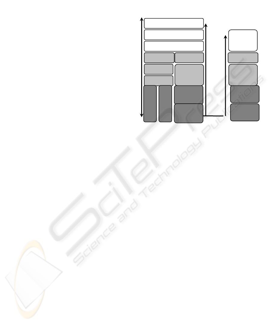
The interconnection of TCP/IP and ZigBee is
depicted on Figure 1. It provides an interface
between ZigBee and IP devices through an abstracted
interface on IP side.
Each wireless sensor group is supported by its
controller providing Internet-based clients with
secure and efficient access to application-related
services over the associated part of gas pipes. In this
case, clients communi-cate to controllers using a
messaging protocol based on client-server and
subscribe-publish patterns employing 1451.1
Network Block functions. A typical configuration
includes a set of sensors generating pressure and
temperature values for the related controller that
computes profiles and checks limits for users of
those or derived values. When a limit is reached, the
safety procedure closes valves in charge depending
on safety service specifications.
Figure 1: Network gateway.
Security configurations in this case can follow the
tiered architecture discussed above. To keep the
system maintenance simple, all wireless
communication uses standard ZigBee hop-by-hop
encryption based on single network-wide key
because separate pressure and/or temperature values,
which can be even-dropped, appear useless without
the overall context. Security in frame of Intranet
subnets stems from current virtual private network
concepts. The discussed application utilizes ciphered
channels based on tunneling between a client and a
group of safety valve controllers. The tunnels are
created with the support of associated
authentications of each client.
The application architecture comprises several
groups of wireless pressure and temperature sensors
with safety valve controllers as base stations
connected to wired intranets that dedicated clients
can access effectively through Internet. The WWW
server supports each sensor group by an active web
page with Java applets that, after downloading,
provide clients with transparent and efficient access
to pressure and temperature measurement services
through controllers. Controllers offer clients not only
secure access to measurement services over systems
of gas pipes, but also communicate to each other and
cooperate so that the system can resolve safety and
security-critical situations by shutting off some of
the valves.
Each controller communicates wirelessly with its
sensors through 1451.5 interfaces by proper
Zi
g
Bee Gatewa
y
App
lication
Zi
g
Bee
Gatewa
y
Trans
p
ort
TCP
,
UDP
IP
802.15.4
MAC
Ethernet
Wireless
802.15.4
PHY
App
. Su
pp
or
t
Network
Layer
DHCP
,
SNMP
App
lication
(
Java
,
…
)
802.15.4
PHY
802.15.4
MAC
App
. Su
pp
or
t
Network
Layer
Embedded
Application
TCP/IP-ZigBee Gateway
ZigBee
ICSOFT 2010 - 5th International Conference on Software and Data Technologies
176
communication protocol. In the discussed case the
proposed P1451.5-ZigBee, which means ZigBee
over IEEE 802.15.4, protocol was selected because
it fits application requirements, namely those dealing
with power consumption, response timing, and
management. The subscriber-publisher style of
communication, which in this applica-tion covers
primarily distribution of measured data, but also
distribution of group configuration commands,
employs IP multicasting. All regular clients wishing
to receive messages from a controller, which is
joined with an IP multicast address of class D,
register themselves to this group using IGMP. After
that, when this controller generates a message by
Block function publish, this message is delivered to
all members of this class D group, without
unnecessary replications.
4 NETWORK MODELING
The current goals of our research in frame of
Internet-level routed networks consist of i) creation
of a unifying model suitable for description of
relevant aspects of real computer networks including
routing information, ACLs (access control lists),
NAT (network address translation), dynamic routing
policy; and ii) delivering methods for automated
verification of dependable properties (e.g.
availability, security, survivability). The project
aims to merge the research on formal methods with
the research on network security to devise a new
method for network security verification.
4.1 Dynamic Network Model
The recent work has focused on studying models
and analysis techniques based on simulation and
network monitoring (Matousek, et al., 2008).
The dynamics of current network models is most
often limited to changes of actual data in time. The
other dimension of dynamics of routed networks
comes from dynamic routing protocols and topology
changes based on the availability of links and link
parameters, e.g. reliability, bandwidth or load.
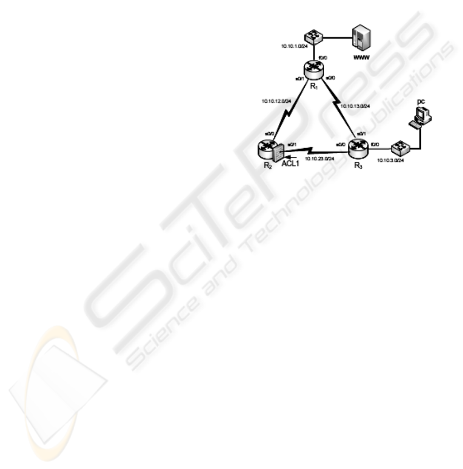
4.2 Application Case Study II
Suppose a small organization running a web server
that provides information to their customers. The
server is placed in the local network equipped with
three routers. A path to the Web server goes through
router R2 that filters traffic by in its input, see
Figure 2. There is a backup line between routers R1
and R3 with higher costs (lower priority). However,
when the link between R2 and R3 goes down, the
traffic is not filtered any more and the web server
can be attacked from the outside network. In another
scenario, the priority line appears between routers
R1 and R3. This line enables to access the Web site
from the PC. When the link goes down, traffic is
redirected by routing tables trough R2. However, R2
entry interface is filtered by ACL1. The connection
from PC to Web server is filtered out and the Web
services are no longer available.
Figure 2: Network example.
These two scenarios present typical situation of a
real-world network with a dynamic behaviour. Our
approach focuses on the area of automatic analysis
of a network that consists of L3 devices (hosts,
routers, firewalls etc.) connected by links and,
optionally, with firewall rules applied on them.
In our work we explore how security and safety
properties can be verified under every network
configuration using model checking (Clarke, et al.,
1999). The model checking is a technique that
explores all reachable states and verifies if the
specified properties are satisfied over each possible
path to those states. Model checking requires
specification of a model and properties to be
verified. In our case, the model of network consists
of hosts, links, routing information and ACLs. The
network security-type properties are expressed in the
form of modal logics formulas as constraints over
states and execution paths. If those formulas are not
satisfied, the model checker generates a
counterexample that reveals a state of the network
that violates the specification. If the formulas are
satisfied, it means, that the property is valid in every
state of the systems, see more detail in (Matousek,
et al., 2008).
NETWORK CONVERGENCE AND MODELING - Design of Interconnecting SW for Intranets and Fieldbuses
177

5 CONCLUSIONS
The paper discusses software architectures for
intermediate system’s control planes belonging to
Intranets and Fieldbuses by two case studies derived
from genuine implementations. The interest is
focused both on network convergence and on
network modeling in application architecture
development.
From the previous discussion it is evident that
the illustrated above network convergence would
influence not only the unification of modeling
techniques, but also the fusion of development
targets such as quality of service assurance in the
same way like empowering development tools by
technology reuse for new application domains.
ACKNOWLEDGEMENTS
The research has been supported in part by the
Czech Ministry of Education in frame of the
Research Intentions MSM 0021630528, Czech
Ministry of Industry and Trade through the grant
FR-TI1/037, by the Brno University of Technology
through the grant FIT-10-S-1, and by the Grant
Agency of the Czech Republic through the grant
GACR 102/08/1429.
The author appreciates contributions to the
presented work by his colleagues Radimir Vrba,
Ondrej Rysavy and Petr Matousek.
REFERENCES
Cach P., Fiedler, P., Sveda, M., Prokop, M., Wagner M.,
2003. A Sensor with Embedded Ethernet, In WSEAS
Transactions on Circuits, Iss.1, Vol.2, pp.213-215.
Cernohlavek, I., Novotny, J., Slama, V., Zahorik, V.,
Sveda, M., 1994. Open-Box Routers with Academic
Metropolitan Networking, Technical Report, Brno
University of Technology (CVIS Department) and
Masaryk University (UIVT Department). Brno.
Clarke, E.M., Grumberg, O., Peled, D.A., 1999. Model
Checking, MIT Press, Boston, MA.
Kania, L., Smolik, S., Sveda, M., Zahorik, V., 1995. The
Brno Academic Computer Network and its Future
Development, In Proceedings INVEX-CCT'95, BVV
Press, Brno, pp.1-5.
Keshav, S., 1997. An Engineering Approach to Computer
Networking: ATM Networks, the Internet, and the
Telephone Network, Addison-Wesley, Reading, MA.
Matousek, P., Rab, J., Rysavy, O., Sveda, M.: A Formal
Model for Network-wide Security Analysis, In
Proceeding of the 15 IEEE International Symposium
and Workshop on the Engineering of Computer-based
Systems, Belfast, GB, IEEE Computer Society, Los
Alamitos, CA, 2008, pp.171-181.
Nguyen, K.-K., Jaumard, B., 2009. Routing Engine
Architecture for Next Generation Routers: Evolutional
Trends, In International Journal of Network Protocols
and Algorithms, Vol.1, No.1, Macrothink Institute,
Las Vegas, Nevada, pp.62-85.
Nucci, A., Papagiannaki, K., 2009. Design, Measurement
and Management of Large-Scale IP Networks:
Bridging the Gap between Theory and Practice,
Cambridge University Press, New York.
Sajdl, O., Bradac, Z., Vrba, R., Sveda, M., 2003. Data
Acquisition System Exploiting Bluetooth Technology,
In WSEAS Transactions on Circuits, Iss.1, Vol.2,
pp.117-119.
Sveda, M., 1993. Routers and Bridges for Small Area
Network Interconnection, In Computers in Industry,
Vol.22, No.1, Elsevier Science, Amsterdam, NL,
pp.25-29.
Sveda, M., Vrba, R., Zezulka, F., 2000. Coupling
Architectures for Low-Level Fieldbuses, In
Proceedings 7th IEEE ECBS'2000 Conference,
Edinburgh, Scotland, IEEE Comp. Soc., pp.148-155.
Sveda, M., Benes, P., Vrba, R., Zezulka, F., 2005.
Introduction to Industrial Sensor Networking. Book
Chapter in M. Ilyas, I. Mahgoub (Eds.): Handbook of
Sensor Networks: Compact Wireless and Wired
Sensing Systems, CRC Press LLC, Boca Raton, FL,
pp.10.1-10.24.
Vrba, R., Sajdl, O., Kuchta, R., Sveda, M., 2004. Wireless
Smart Sensor Network System, In Proceedings of the
Joint International Systems Engineering Conference
(ICSE) and The International Council on Systems
Engineering (INCOSE), Las Vegas, Nevada.
ZigBee, 2006. ZigBee Specification. ZigBee Alliance
Board of Directors Website http://www.zigbee.org/.
ICSOFT 2010 - 5th International Conference on Software and Data Technologies
178
