
KBE TEMPLATE UPDATE PROPAGATION SUPPORT
Ontology and Algorithm for Update Sequence Computation
Olivier Kuhn
1,2,3
, Thomas Dusch
3
, Parisa Ghodous
1
and Pierre Collet
2
1
Universit
´
e de Lyon, CNRS, LIRIS, UMR5202, F-69622, Lyon, France
2
Universit
´
e de Strasbourg, CNRS, LSIIT, UMR7005, F-67412, Strasbourg, France
3
PROSTEP AG, Darmstadt, Germany
Keywords:
Ontology, Update strategy, Knowledge-based engineering, KBE templates, Ranking.
Abstract:
This paper presents an approach to support Knowledge-Based Engineering template update propagation. Our
aim is to provide engineers with a sequence of documents, giving the order in which they have to be processed
to update them. To be able to compute a sequence, we need information about templates, Computer-Aided
Design models and their relations. We designed an ontology for this purpose that will, after inferring new
knowledge, provide a comprehensive knowledge about the templates and assemblies. This information is then
used by a ranking algorithm that we have developed, which provides the sequence to follow to be able to
update models efficiently without a deep analysis of the dependencies. This will prevent mistakes and save
time as the analysis and choices are automatically computed.
1 INTRODUCTION
Nowadays, high-end industries such as automotive or
aerospace industries are designing products that are
more and more complex and that integrate various
disciplines. The product diversification and the in-
crease of the model range has motivated new IT tools
and has impacted the product development process
(Katzenbach et al., 2007). One change during the
last years is the democratisation of Knowledge-Based
Engineering (KBE) which has become a standard in
product development. KBE is a large field at the
crossroads of Computer-Aided Design (CAD), artifi-
cial intelligence and programming. It facilitates the
reuse of knowledge from previous design choices and
thus reduces design time and costs. Standardization
is also a way to reuse knowledge. Furthermore, Du-
denh
¨
offer (2000) said that the standardisation and the
use of common parts and platforms is a key factor for
efficiency in the automotive industry. One solution to
reuse knowledge is the use of KBE templates.
KBE templates are intelligent documents or fea-
tures that aim at storing know-how and facilitate its
reuse. They are designed to adapt themselves to var-
ious contexts, which can lead to some maintenance
problems. Maintaining a huge number of templates is
quite a challenging task because of the many relations
created with other documents. Modifications can be
made to templates to add new functionalities or fix
some bugs. This is why there is a need to propagate
these modifications to existing copies of the template,
called instances, that are used in a specific context, for
instance, an engine assembly.
The work presented in this paper targets the prob-
lematic of template update propagation. We use
an ontological representation of templates and CAD
models to infer new knowledge. This knowledge
is then used to compute an update sequence, which
can then be used by engineers in charge of propagat-
ing changes. With this tool, we remove the task of
analysing dependencies between documents and eval-
uating the impact of the relations on the update prop-
agation.
This paper is structured as follows. In section 2
the problematic is presented. Section 3 presents sev-
eral research works related to KBE templates. Section
4 describes our approach. In section 5, we present the
developed ontology. Section 6 presents how we com-
pute an update sequence for the update propagation.
In section 7 an application of the work is presented.
Finally, in section 8 some conclusions are given.
5
Kuhn O., Dusch T., Ghodous P. and Collet P. (2010).
KBE TEMPLATE UPDATE PROPAGATION SUPPORT - Ontology and Algorithm for Update Sequence Computation.
In Proceedings of the 12th International Conference on Enterprise Information Systems - Artificial Intelligence and Decision Support Systems, pages
5-12
DOI: 10.5220/0002867100050012
Copyright
c
SciTePress
2 TEMPLATE UPDATE
PROBLEMATIC
2.1 KBE Template Definition
The aim of Knowledge-Based Engineering is to cap-
ture and reuse the intent and product design knowl-
edge through parameters, rules, formulas, automa-
tion, and also knowledge templates. The reuse of
knowledge allows to speed up the design process by
reducing design recreation and to save costs. The
ultimate goal is to capture information related to
best-practices and design know-how in a company.
Knowledge-Based Engineering is nowadays used by
many companies and has proven its advantages. Ex-
amples of enhancements resulting from the use of
KBE are presented in (Gay, 2000; Chapman and Pin-
fold, 2001).
Templates are knowledge-based applications that
allow the storage and the reuse of know-how and
company best practices. Knowledge-based applica-
tions include a wide set of elements that contains
documents, parametric CAD models, software, KBE,
CAE analyses etc. They are designed in order to adapt
themselves to a given context regarding some defined
inputs given by the context. The process of putting
a template into a context and setting the inputs of
the template is called “instantiation.” For instance, in
CATIA V5, a Dassault CAD system, the instantiation
process will create a copy of the template, which we
call “template instance,” then put it into the context
and finally link the elements from the context to the
template instance’s inputs. At the end of the process
we have two entities that have separate life cycles: the
template definition and its template instance.
In addition to knowledge storage, templates are
also used to provide standardized parts and assem-
blies for design activities, and to integrate proven de-
sign solutions into future product design processes
(Katzenbach et al., 2007). Katzenbach et al. (2007)
also exposed that the mandatory use of template-
based design processes enhances the design maturity
during the complete design phase. Moreover, Kam-
rani and Vijayan (2006) showed an integrated design
approach based on templates technologies that allows
to reduce drastically the development time needed for
new products.
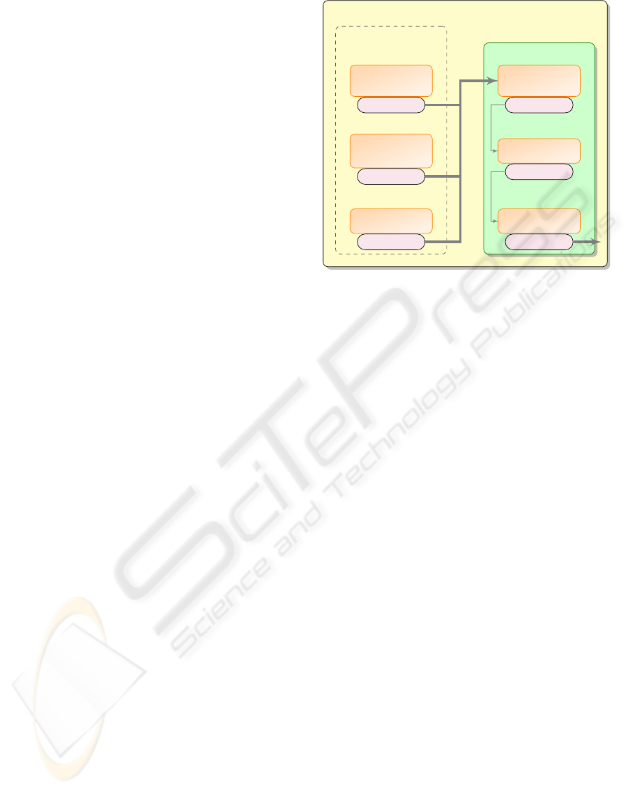
Figure 1 presents the generic structure of an as-
sembly template instance in a context. The context
is composed of several entities called the “external
specifications,” which are other elements present in
the context that will provide parameters’ value or ge-
ometry to the template. The inputs of the template are
gathered in the “adapter model,” which is composed
Template Context
Concept
model
Publications
Design
specifications
Publications
Components
Publications
External
specifications
Adapter
model
Publications
Construction
Publications
Output
Publications
Template instance
Figure 1: Generic structure of a CAD template with link
flow (Arndt et al., 2006).
of basic geometry to guide the “construction.” The
“output” is used to present some specific elements of
the template to the context. References to other doc-
uments are based on publications. The aim of using
publications is to provide a named reference of an el-
ement within the document, that can be easily recog-
nised and referred to. So if the content of a document
changes, the links between documents will not be bro-
ken as we do not refer directly to the elements inside
the document. The figure also presents the link flow
(represented by arrows) that represents the hierarchy
of the model.
2.2 Addressed Problematic
In large and complex assemblies like those present
in automotive or aerospace industries, the number of
templates and template instances can reach several
thousands and even more. This implies a huge effort
to maintain them as they become more complex by
incorporating new potential variants for future design
(Katzenbach et al., 2007). There is a second challenge
regarding template update, that concerns the propa-
gation of the modifications done to templates. Luk-
ibanov (2005) initiated this problematic of template
management because Product Data Management sys-
tems and CAD software did not address it to a full ex-
tent. Once a template has been modified and validated
in order to suit new requirements or fix some bugs,
changes should be propagated to other templates and
their instances to use the same version everywhere.
The complexity of the problem comes from the
heterogeneity of the data. There are several types of
documents that can be linked together for several rea-
ICEIS 2010 - 12th International Conference on Enterprise Information Systems
6

Launch
update
(a)
(b)
Analyse do cument
Update ontology
instances
Run inference
engine
Compute up date
sequence
Update
template instances
Updated documents
New do cument or new document version
Figure 2: Developed process for template update propagation.
sons such as a parameter dependency, parent-child re-
lation etc. All these relations may have an impact on
the propagation of updates. The relations have to be
analysed and represented in a suitable format in order
to allow a computer software to take advantage of the
knowledge, to analyse the current state and to create
a sequence of updates.
In this paper, we address the template update prop-
agation to instances. Our objective is to provide engi-
neers with a sequence of necessary updates, in order
to help them to achieve the template instances updates
faster and with less difficulties and errors.
3 RELATED WORK
KBE templates is a recent technology that has be-
come the purpose of many research works and ap-
plications. The ability of templates to adapt them-
selves to a given context has been used by Siddique
and Boddu (2005) to integrate the customer into the
design process. They proposed a mass customisation
CAD framework that takes into account user param-
eters to automatically generate a CAD model from
predefined templates. The automotive industry has
also integrated templates into their development pro-
cesses. Haasis et al. (2007) and Katzenbach et al.
(2007) presented the template-based process at Daim-
ler AG, an automotive enterprise. There will be a need
in the future to standardize component concepts be-
tween product families to face the complexity of prod-
ucts and processes. The solution they have adopted is
to resort to KBE templates in the engineering process.
Mbang (2008) proposed the use of KBE templates to
integrate together Product, Process and Resource as-
pects, in order to make it seamless to the designers.
Some research have been made concerning tem-
plate maintenance. Lukibanov (2005) addressed the
problem of template management and distributing the
latest versions of templates. The proposed solution
involves ontologies that are used as a knowledge rep-
resentation layer about templates and their intercon-
nections. An ontology allows to represent concepts
and relationships between these concepts (Mizuguchi,
2003). Ontologies also provide a solution to find de-
pendencies and to check the consistency of the on-
tology thanks to an inference process. One ontology
is created from each templates by mapping them to
the knowledge model. Each ontology describes the
inputs, outputs and links to CAD models of the corre-
sponding template, and uses the visualisation of these
information to propagate changes to other templates.
However his approach does not handle template in-
stances and focuses on the CATIA V5 CAD system.
4 APPROACH
To propagate modifications to template instances, we
need to take into account the propagation to other
templates because templates can be linked together,
but they can also be composed of instances of other
templates. This is why we propose to adapt and ex-
tend the approach presented by Lukibanov (2005) to
take into account template instances and to try to ab-
stract the methodology so that it can be applied to var-
ious CAD systems.
Figure 2 presents the process we have developed
to propagate the template modifications. The process
is decomposed into two main parts.
In the first part (figure 2.a), we handle an infor-
mation database about templates and CAD models.
We have considered that having one ontology for each
template does not scale well as we will also handle
data on template instances and other assemblies. The
solution we propose is to define one domain ontol-
ogy based on the analysis of template concepts, CAD
systems and existing ontologies. Concepts in our on-
tology will be instantiated by analysing CAD mod-
els and templates to gather relevant information for
the template update propagation. Data retrieved from
CAD models are raw data. Some information is not
visible or incomplete regarding our needs. For this
reason, we use an inference engine on the instantiated
ontology to enhance the classification and discover in-
formation not directly accessible in the CAD models.
This ontology is presented in section 5.
The second part is dedicated to the propagation of
changes (figure 2.b). We take advantage of inferred
knowledge to compute an update sequence to support
engineers in their tasks. Locating all relevant tem-
plate instances incorporated in huge assemblies and
KBE TEMPLATE UPDATE PROPAGATION SUPPORT - Ontology and Algorithm for Update Sequence Computation
7

estimating the consequences of the necessary changes
to be made could easily be a full time job. Further-
more, some relations are not explicitly available and
their impact on the update has to be estimated. This
is why we propose an algorithm that is in charge of
computing an update sequence. This algorithm takes
advantage of the knowledge of the domain we have
gathered in the ontology and of the enriched infor-
mation on the templates and models available in the
ontology. More details are given in section 6.
5 ONTOLOGY DESIGN
5.1 Aim of the Ontology
To generate an update sequence, the algorithm re-
quires information about the type of the documents
and the existing relations between documents. To pro-
vide these information in a computer understandable
and processable format, we have developed an Ontol-
ogy represented with the Web Ontology Language
1
(OWL). We have chosen the OWL representation lan-
guage for several reasons. OWL is based on open
standards and is a W3C recommendation since 2004.
Right now, we are using OWL-DL, a sublanguage
which is named in correspondence with Description
Logic on which it is based. It is the largest set of
OWL that provides decidable reasoning procedures.
Katzenbach et al. (2007) pointed out from their
study that relations between documents need an effi-
cient visualisation tool to have an overview on all in-
terdependencies. With this ontology, we want to pro-
vide a classification and an efficient overview of all
explicit and implicit dependencies in templates and
assemblies.
5.2 Followed Methodology
To develop our ontology, we decided to use the
Ontology Development 101 methodology (Noy and
McGuinness, 2001) for its simplicity and its lightness.
This methodology is composed of seven steps.
The first step is to define the domain of the ontol-
ogy. The domain of our ontology focuses on our prob-
lematic: concepts and relations are related to KBE,
templates and CAD models. Such specific ontologies
are called “application ontology.”
To design our ontology, we had a mixed top-down
and bottom-up approach. We started from the con-
cepts and at the same time from a CAD system anal-
1
http://www.w3.org/TR/owl-guide/
ysis. Our idea is to make them meet so that the ontol-
ogy includes details linked with generic concepts.
The second step of the methodology is to reuse
existing ontologies. We have found no available or
reusable ontology that can be reused for our prob-
lematic. However there are standards in the prod-
uct design field from which we can extract and reuse
useful information and concepts. The most famous
is the “STandard for the Exchange of Product model
data” (STEP, 1994) that is also referenced as the ISO
10303 norm. STEP provides standards for product
data representation and covers a broad range of appli-
cations from geometric and topological representation
to kinematics, passing by product life cycle. STEP
can thus provide some elements for the needed ab-
straction level for a generic document representation
in the ontology to ease the integration of other CAD
systems. Then we need to enrich it with a detailed
analysis of the problematic and concrete systems.
5.3 System Analysis
Step three of the methodology is to enumerate the im-
portant terms that will appear in the ontology in order
to define the concepts and the object properties. For
this purpose, we analysed the CATIA V5 CAD system
from Dassault Systems, that is used in automotive,
aerospace or ship building industries. Our analysis
was focused on knowledge elements and relations be-
tween documents (Multi-Model links in CATIA V5).
CATIA V5 integrates KBE workbenches that pro-
vide KBE template mechanisms to create and instanti-
ate templates. There are three main types of templates
available: feature templates, document templates and
process templates. We defined process templates as
out of the scope of our work because they address
CAx processes and we focus on CAD. It is also possi-
ble to use standard CAD models as templates without
resorting to the specific CATIA KBE workbench. But
with this method, there are no explicit template defi-
nitions and no support tool for template instantiation.
If we have a look at template instances, we can see
that this term does not exist within CATIA V5. Tem-
plate instances are not handled and are considered as
standard documents with no possibility to recognise
them.
Regarding the relations between documents, we
identified 19 different types of links. Each link in-
volves two documents, one for the source and the
other for the target of the link. The links do not all
have the same impact on the update propagation. For
this reason we need a classification of link types de-
pending on their impact.
From this analysis, we have defined the main
ICEIS 2010 - 12th International Conference on Enterprise Information Systems
8
terms and also some of their relationships. Concern-
ing templates, we have to take into account the spe-
cific CATIA V5 templates as well as models used as
templates. Terms related to template instances have
also to be taken into account and a solution to track
and classify template instances has to be integrated in
the ontology. Regarding the relations, we classified
them and created the new term of “dependency link”
that will gather all links that will influence the update
propagation.
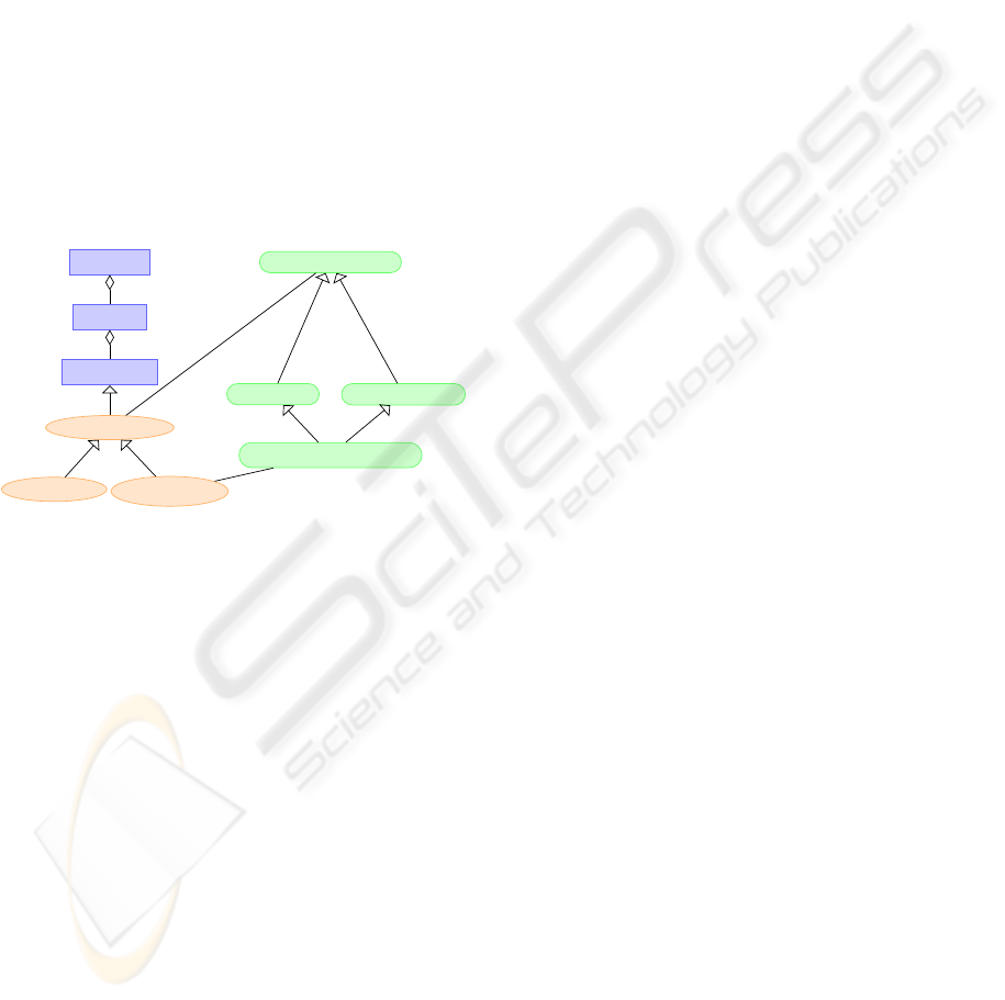
5.4 Ontology Description
Figure 3 presents a part of the developed ontology. In
our mixed approach to design the ontology, we started
from the top by defining the upper level of our ontol-
ogy (blue rectangles) by creating the document def-
inition concepts and relations inspired by the STEP
standard.
Product
Version
Definition
Document
Instance
Template
CATDocument
CATProduct
CATPart
Document template
is-a
is-a
is-a
≡
≡
Figure 3: Extract of the ontology with the abstraction level
and the CAD system concepts (here CATIA V5).
Then we defined the CAD system specific con-
cepts of the ontology (green rounded rectangles)
on the basis of the CATIA terminology and the
new terms we have identified which are not de-
fined within the CAD system (section 5.3). Those
new concepts are defined acording to existing con-
cepts and relations in order to deduce them with
an inference engine. For instance, we defined a
new concept called “PartAsTemplate,” which de-
fines a CATPart document that contains no tem-
plate definition from CATIA V5 but that is used
as a template. Its definition with Description Log-
ics notation is the following: PartAsTemplate ≡
CAT Part ∩ ¬(∃hasDe f intion.DocumentTemplate) ∩
∃hasID.TemplateID.
Finally, we integrate mid-level concepts such as
system independent template concepts like “tem-
plate” and “template instance” (orange ellipses). All
these concepts are linked together with “is-a,” equiv-
alence or aggregation relationships.
Concerning the relations between documents, we
represented them as object properties. We added the
19 link types present in CATIA V5. To be able to
track instances, we created a relation between tem-
plate definitions and template instances by adding an
identifier to the models that will be shared between a
template and its instances. We also defined the inverse
links, with the inverse property axiom, to be able to
navigate easier between documents because in CA-
TIA V5, links are unidirectional and a document is
not aware of the presence of a link targeting it.
All these data constitute the foundation to com-
pute an update sequence for the update propagation.
6 UPDATE SEQUENCE
COMPUTATION
Our goal is to provide engineers in charge of propa-
gating changes in template definitions to its instances
and to other templates with a comprehensive sequence
they can follow. This sequence will give them an or-
dered list of documents (with a corresponding rank)
that have to be updated or replaced. Following this se-
quence rank after rank will save time as the engineers
do not have to analyse the complex situation with all
its interdependencies. This will also prevent redun-
dant or useless updates.
6.1 Graph Representation
The data representation we created with the ontology
can be seen as a directed graph with documents in-
stances as nodes and their relationships as edges. The
specificity of the obtained graph is that nodes and ver-
tices are typed. Their types depend on the concepts
and object properties they represent, so one node can
have several types. Our algorithm will work on this
graph to extract relevant nodes and to assign them a
rank.
6.2 Approach
We tackled the problem with a ranking approach
based on relations between documents defined in the
ontology. The objective is to build an ordered se-
quence by assigning a rank r
k
(where k is the rank)
to each document. The rank represents the order in
which documents have to be processed. Several doc-
uments can have the same rank, meaning that they can
be processed at the same time.
Our approach was inspired by research on hi-
erarchical structure visualisation and directed graph
drawing (Gansner et al., 1993; North and Woodhull,
KBE TEMPLATE UPDATE PROPAGATION SUPPORT - Ontology and Algorithm for Update Sequence Computation
9
2002). The results of their work, is an efficient algo-
rithm to draw hierarchical graphs. An implementation
has been made in graphviz
2
, an open-source graph vi-
sualisation tool. The initial version of the algorithm
was proposed in (Sugiyama et al., 1981). It is com-
posed of 4 phases:
1. Place the graph nodes in discrete ranks.
2. Order nodes within rank to avoid crossing edges.
3. Compute the coordinates of nodes.
4. Compute edges’ splines.
We focused our interest on the first phase where nodes
are ranked.
This method builds a hierarchy composed of n lev-
els, from a directed and acyclic graph. The hierarchy
is denoted G = (V, E, n, σ), where:
• V is a set of vertices such as:
V = V
1
∪V
2
∪ ···∪V
n
(V
i
∩V
j
=
/
0, i 6= j)
where V
i
is the set of vertices of rank i and n the
height of the hierarchy.
• E is a set of edges, where each edge is unique.
• σ is a set of sequence σ
i
for each V
i
. σ
i
is
the sequence of vertices within V
i
such as σ
i
=
v
1
, v
2
, . . . , v
|V
i
|
with |V
i
| the number of vertices of
V
i
.
To create the hierarchy, each directed edge e =
(source,target) has to obey the following condition:
e = (v
i
, v
j
) ∈ E, v
i
∈ V
i
and v
j
∈ V
j
satisfies i < j (1)
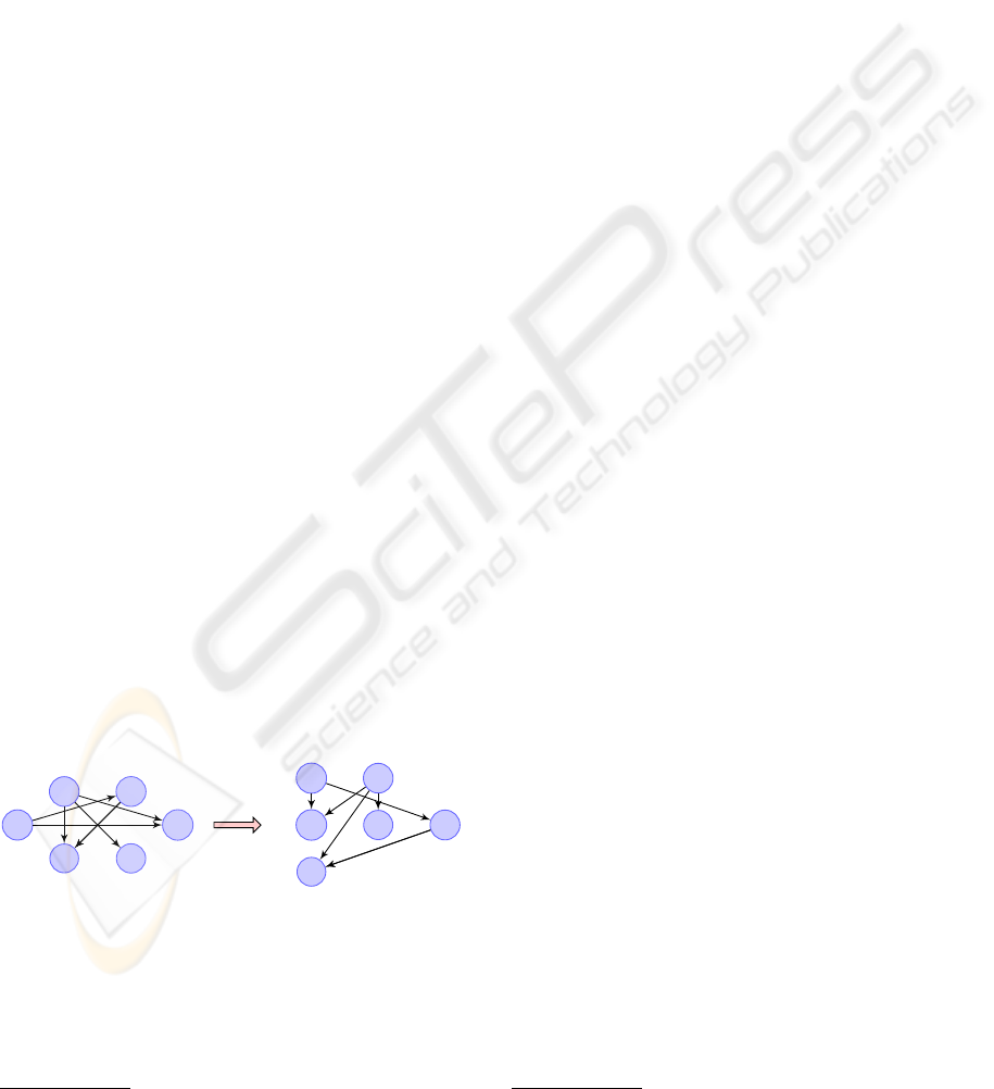
The result of this phase of the algorithm can be
seen in figure 4. It has been applied to a small ex-
ample composed of six vertices and six edges. The
result (b) shows three ranks (n = 3) and validates the
condition presented in equation 1.
A
B C
D
EF
(a)
A B
CD E
F
1
2
3
(b)
Figure 4: Acyclic directed graph (a) and its result (b) after
the first phase of the (Sugiyama et al., 1981) algorithm.
We adapted and extended this ranking algorithm
to make it produce an update sequence for the tem-
plate update propagation.
2
http://www.graphviz.org/
6.3 Adaptation of the Algorithm
The data from templates and models generate a more
complex graph as the relations and links between the
documents can have various effects on the update
propagation. This is why we use the classification
made in the ontology.
In our approach we do not take into account the
sequences σ as we are just interested in placing docu-
ments in the good rank.
The original modified documents are the inputs of
the algorithm and will be placed at the first rank r = 1.
Starting from these documents, the algorithm builds
the hierarchy. We query the ontology for the types
of documents and the links that propagate the update
from these documents. Depending on the types of the
documents, several actions can be undertaken. The
documents linked with an “inverse dependency link”
are added at rank r + 1 as they have to be processed
after the dependency is satisfied. Then the algorithm
continues with the rank r + 1 where the documents
were just added. If the current document is a tem-
plate, the behaviour is different. As templates may
be containers, the re-instantiation of a template has to
be done after all the included documents have been
updated.
To be able to perform a re-instantiation, we need
to load the document that contains the template in-
stance before doing the action. So if r
ti
is the rank of
the template instance, its containing assembly parent
should be located in a previous rank such as its rank
r
parent
< t
ti
. The worst case complexity of the result-
ing algorithm is linear (O(h) with h the total number
of nodes).
7 APPLICATION
7.1 Developments
The presented approach has been implemented in a
system composed of two parts.
The first part is CAD system dependant. In our
case we used CATIA V5 and the C++ CAA API to
analyse CAD models and templates. Data extracted
are then transferred in an XML format to the second
part of our system.
The second part is in charge of maintaining the on-
tology instances and computing the update sequence.
We developed a JAVA application using the OWL-
API
3
to manipulate the OWL ontology and the in-
ference engine. The presented ontology was cre-
3
http://owlapi.sourceforge.net
ICEIS 2010 - 12th International Conference on Enterprise Information Systems
10
ated using Prot
´
eg
´
e 4
4
(Noy et al., 2001) that is an
open source ontology editor. The implementation
of our update sequence computation algorithm was
also done in JAVA as it uses the OWL-API to ac-
cess the ontology data. Concerning the inference en-
gine, we have chosen FACT++ (Tsarkov and Hor-
rocks, 2006), an efficient OWL-DL reasoner directly
usable through the OWL-API.
7.2 Scenario
Our scenario uses the CATIA V5 CAD system. The
scenario is composed of 92 CAD models of differ-
ent types (CATParts, CATProducts, CATIA V4 mod-
els). Within this set of documents are 9 templates:
8 document templates with some of them containing
instances from other templates and 1 “User Defined
Feature,” which is a feature template like a predefined
hole.
Our study case starts with the modification of ge-
ometry elements in one document template. We con-
sider that the template has been validated and is ready
to be used. We want now to update related documents
and all instances to have up-to-date models.
Without any support tool, the persons in charge
of propagating the modifications will have to locate
all the related template instances and related docu-
ments through links and references. Once they have
all these information, they can make the necessary
changes. Finally, the new modifications may also
have some consequences on other templates or their
instances. . . all these steps are time consuming and
can lead to mistakes or leaving out some documents.
7.3 Application and Results
First of all, we need up-to-date information of tem-
plates and CAD models. Currently we analyse all
models and recreate instances in the defined ontology
without instances (in the future we plan to enable in-
cremental updates because the full analysis is rather
time consuming). After this step, we have a compre-
hensive overview of models and their relationships.
Then the user has to select the modified templates and
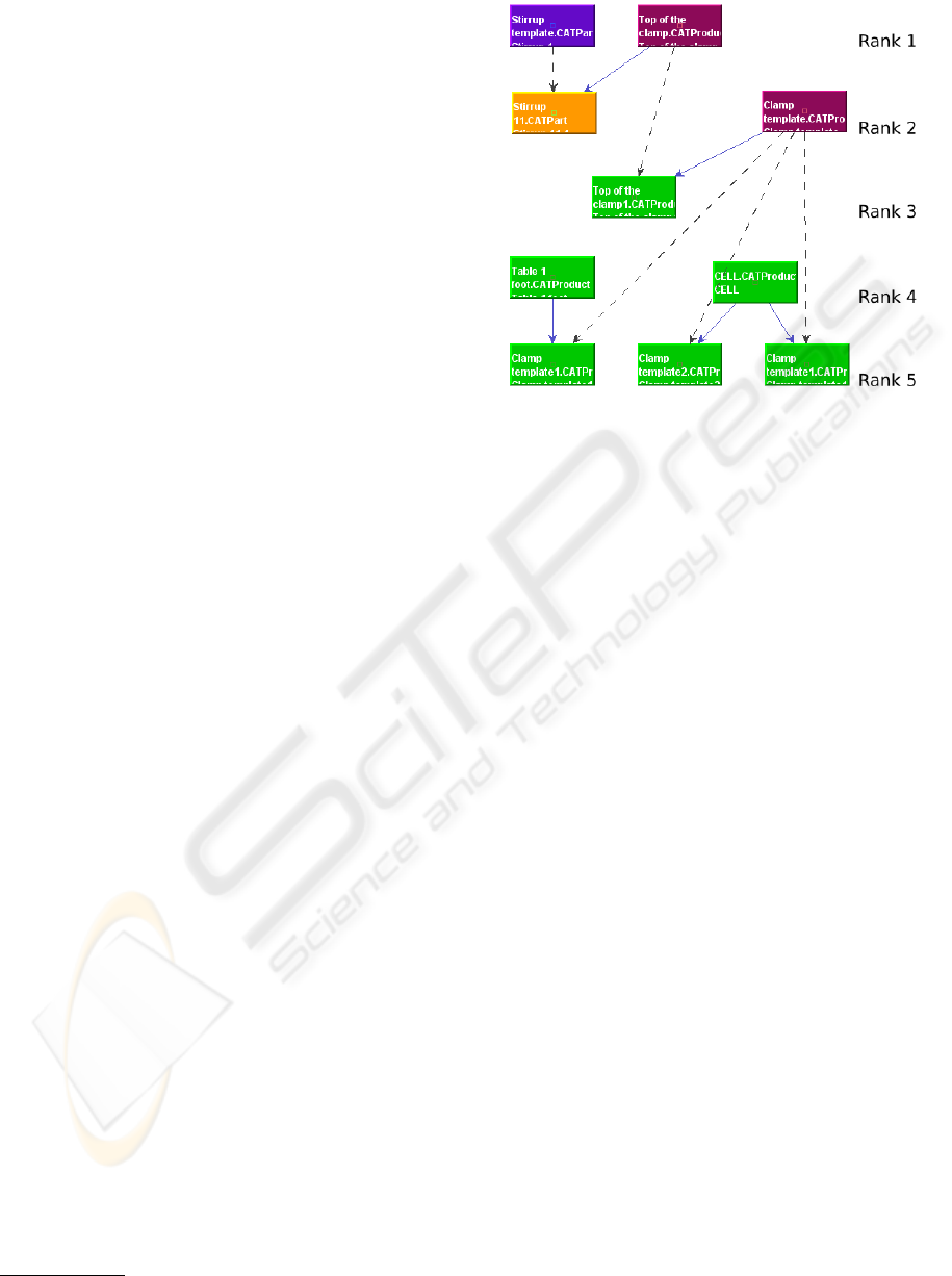
launch the update sequence computation.
An example of result for one modified template is
presented in figure 5. The 92 models problem was
computed in approximately 300 ms on a Pentium M
1.8Ghz. It shows the documents (boxes) that have to
be updated and the order in which they have to be pro-
cessed. The first documents to be handled are located
at rank 1. The dotted arrows represent the “instance
location link,” which is the link from a template to one
4
http://protege.standfort.edu/
Figure 5: Example of update sequence.
of its instances. The other arrows target a document
contained in the link source document. Other types of
relations present in the ontology can also be shown.
Engineers are thus provided with means to merely
follow the sequence rank after rank, load given doc-
uments and apply the changes. This eliminates the
unproductive task of searching relations through doc-
uments and their documentation and the focus can be
put on the updates.
8 CONCLUSIONS AND
PERSPECTIVES
In this paper, we presented a solution to propagate
changes made in KBE templates to their instances
and related documents. Update propagation is a com-
plex and time consuming task. The complexity comes
from the size and the heterogeneity of the network
representing documents and their relations. The so-
lution proposed aims at supporting engineers in the
task of updating related templates and instances after
template definitions were modified.
The main benefits of this approach are the speedup
of the global task of propagating template updates,
as well as to avoid incomplete updates. In a set of
several thousand of models, it is hard to have a good
overview of all dependencies to find needed informa-
tion. This is even more complex due to non-explicit
relations and links that are not represented within the
CAD system such as, for example, the template in-
stances location.
Our approach is based on an OWL ontology that
we defined from the analysis of the problematic and
KBE TEMPLATE UPDATE PROPAGATION SUPPORT - Ontology and Algorithm for Update Sequence Computation
11

CATIA V5 as example. This ontology also includes
an abstract level composed of concepts inspired from
the STEP standard, to facilitate the integration of
other CAD systems. The aim of the ontology is to
represent knowledge from KBE templates and CAD
models. We also resort to a reasoner on the ontol-
ogy to infer knowledge that is not provided by the
data extraction from KBE templates and CAD mod-
els. These information are then used by a ranking al-
gorithm that will provide an update sequence to sup-
port engineers.
Further improvements can be made to enhance
the global process of changes propagation. The first
would be to automate the model update or template
instance replacement. It would also be interesting to
investigate OWL 2, which has become a W3C rec-
ommendation in October 2009, to evaluate its bene-
fits comparing to OWL DL for data representation.
Further investigations will include the test of our ap-
proach on real industrial cases to evaluate its perfor-
mance on large assemblies.
REFERENCES
Arndt, H., Haasis, S., and Rehner, H.-P. (2006). CATIA V5
Template zur Umsetzung von Standardkonzepten. In
Verlag, V. T. F., editor, Karosseriebautage Hamburg,
Internationale Tagung.
Chapman, C. B. and Pinfold, M. (2001). The application of
a knowledge based engineering approach to the rapid
design and analysis of an automotive structure. Ad-
vances in Engineering Software, 32(12):903–912.
Dudenh
¨
offer, F. (2000). Plattform-effekte in der Fahrzeug-
industrie. In Controlling, volume 3, pages 145–151.
Gansner, E. R., Koutsofios, E., North, S. C., and Vo, K.-
P. (1993). A technique for drawing directed graphs.
IEEE Trans. Softw. Eng., 19(3):214–230.
Gay, P. (2000). Achieving competitive advantage through
knowledge-based engineering: A best practise guide.
Technical report, British Department of Trade and In-
dustry.
Haasis, S., Arndt, H., and Winterstein, R. (2007). Roll
out template-based engineering process. In Daimler-
Chrysler EDM—CAE Forum.
Kamrani, A. and Vijayan, A. (2006). A methodology for in-
tegrated product development using design and man-
ufacturing templates. Journal of Manufacturing Tech-
nology Management, 17(5):656–672.
Katzenbach, A., Bergholz, W., and Rohlinger, A. (2007).
Knowledge-based design an integrated approach. In
Heidelberg, S. B., editor, The Future of Product De-
velopment, pages 13–22.
Lukibanov, O. (2005). Use of ontologies to support de-
sign activities at DaimlerChrysler. In 8th International
Prot
´
eg
´
e Conference.
Mbang, S. (2008). Durchg
¨
angige Integration von Produkt-
modellierung, Prozessplannung und Produktion am
Beispiel Karosserie. In CAD - Produktdaten ”Top Se-
cret” ?!
Mizuguchi, R. (2003). Tutorial on ontological engineering
- part 1: Introduction to ontological engineering. In
New Generation Computing, volume 21, pages 365–
384. OhmSha&Springer.
North, S. C. and Woodhull, G. (2002). Graph Drawing,
chapter On-line Hierarchical Graph Drawing, pages
232–246. Springer Berlin / Heidelberg.
Noy, N. and McGuinness, D. (2001). Ontology develop-
ment 101: A guide to creating your first ontology.
Technical report, Stanford University.
Noy, N. F., Sintek, M., Decker, S., Crubezy, M., Fergerson,
R. W., and Musen, M. A. (2001). Creating seman-
tic web contents with protege-2000. IEEE Intelligent
Systems, 2(16):60–71.
Siddique, Z. and Boddu, K. (2005). A cad template ap-
proach to support web-based customer centric prod-
uct design. Journal of Computing and Information
Science in Engineering, 5(4):381–386.
STEP (1994). ISO 10303 - industrial automation systems
and integration - product data representation and ex-
change.
Sugiyama, K., Tagawa, S., and Toda, M. (1981). Methods
for visual understanding of hierarchical system struc-
tures. IEEE Intelligent Systems Transactions On Sys-
tems, Man, And Cybernetics, 11(2):109–125.
Tsarkov, D. and Horrocks, I. (2006). Fact++ description
logic reasoner : System description. In International
Joint Conference on Automated Reasoning, number 3,
pages 292–297.
ICEIS 2010 - 12th International Conference on Enterprise Information Systems
12
