
EVALUATING UML SEQUENCE MODELS USING THE SPIN
MODEL CHECKER
Yoshiyuki Shinkawa
Ryukoku University, 1-5 Seta Oe-cho Yokotani, Otsu 520-2194, Japan
Keywords:
UML, Model checking, Model consistency, Formal methods.
Abstract:
UML sequence diagram is one of the most important diagrams for behavior modeling, however there are few
established criteria, methodologies and processes to evaluate the correctness of the models depicted by this
diagram. This paper proposes a formal approach to evaluating the correctness of UML sequence models using
the SPIN model checker. In order to deal with the models by the SPIN, they must be expressed in the form of
Promela codes and LTL formula. A set of definite rules is presented, which can extract the above codes and
formulae from given UML sequence models.
1 INTRODUCTION
UML sequence diagram is one of the most important
diagrams to express the behavior of a system com-
posed of multiple objects (Ambler, 2004). In spite of
superior modeling capability of UML sequence dia-
gram, there are several difficulties when applying it
to software development at the implementation level.
Firstly, the models expressed in the form of sequence
diagrams only represent the sequence of messages
between the involved objects, and therefore we can
not recognize the functionality of the systems through
these models. Secondly, we can draw arbitrary mes-
sage flow between any objects, therefore incorrect se-
quence diagrams might possibly be created, which
show the wrong behavior.
As a result, it becomes a hard task to evaluate
the correctness of sequence models
1
. Several efforts
have been made to formalize UML sequence models
for rigorous software design and verification (Shen
et al., 2008) (Damm and Harel, 1998) (Knapp and
Wuttke, 2006). However no concise criterion or pro-
cess has been provided to verify the correctness of se-
quence models. This paper proposes a formal process
to verify correctness on sequence models through a
model checking technique (Clarke et al., 1999). The
SPIN model checker (Holzmann, 2003) is used as a
checking tool.
1
In this paper, the models that are depicted by the UML
sequence diagram is referred to as “sequence models”.
2 A BASIC STRUCTURE OF A
SEQUENCE MODEL
A sequence model, which is expressed in the form
of a UML sequence diagram, represents the behav-
ior of a system by showing how the involved objects
interact. This interaction between the objects is de-
scribed as message passing between them. When a
message is sent from an object, it means the associ-
ated method with the message is invoked in the re-
ceiving object, or the message is sent through a mes-
saging mechanism like JMS (Java Message Service)
(Richards and Monson-Haefel, 2009). The above ob-
jects are depicted as lifelines in a sequence model, and
a synchronous or an asynchronous message is passed
between them.
Regardless of the implementation of a sequence
model, both messages types finally result in the ex-
ecution of the corresponding methods. Since the
method execution could possibly change the state of
the related objects, we can define the behavior of a
sequence model based on state transition. In order
to define the state transition of a sequence model, we
first define the state of each object formally.
An object is composed of the two parts, namely
the data definition part and the method definition part.
The data definition part declares a list of variables as-
sociated with data types, which are either primitive or
reference data types. If a variable is associated with a
primitive data type, it has a value, whereas a variable
with a reference data type refers to another object, and
it can not have a value.
417
Shinkawa Y. (2010).
EVALUATING UML SEQUENCE MODELS USING THE SPIN MODEL CHECKER.
In Proceedings of the 12th International Conference on Enterprise Information Systems - Information Systems Analysis and Specification, pages
417-422
DOI: 10.5220/0002870304170422
Copyright
c
SciTePress

Such an object can be denotes as a tuple
O = hD , M i
where D is a set of variables x
1
, ··· , x
m
, of which
data types are D
1
, ··· , D
m
, and M is a set of meth-
ods M
1
, ··· , M
n
in the object.
If D
i
is a primitive data type, it has e value, which
is denoted as val(x
i
) in this paper. The state of an
object is determined by the values of these variables,
however a variable with a reference data type can not
have a value.
In order to define the state of an object with refer-
ence data types, we introduce the state function for an
object O and a variable x
i
as
S (O ) = hS(x
1
),··· , S(x
m
)i
where S(x
i
) is defined as follows
2
.
S(x
i
) =
(
val(x
i
) (if x
i
is a primitive data type)
S (x
i
) (if x
i
is a reference data type)
If x
i
is a reference data type and thereference is cyclic,
that is, x
i
either
1. refers to the original object O itself, or
2. refers to an object that refers to O directly or indi-
rectly.
In such case, S (O ) occurs during the reduction of
S (x
i
), and we have to remove this S(O ) in order to
avoid the infinite loop.
Using this state function S , the state of a sequence
model composed of the objects O
1
, ··· , O
p
can be de-
fined as the tuple of object states
hS (O
1
),··· , S (O
p
)i
The state of each object is updated only by method
executions within the object, if the object is fully en-
capsulated. In order to simplify the discussion, we
assume all the objects are fully encapsulated. How-
ever, the discussion can be extended to more generic
cases.
As discussed above, message passing, whether
synchronous or asynchronous, causes a method ex-
ecution. A message in a sequence model is denoted
as a line with an arrow, along with an operation name
and parameters on it. The operation name represents
the method name to be executed, and the parameters
are the arguments of the method.
Since a method is invoked when the correspond-
ing message arrives to the lifeline associated with the
method, the state transition from the pre-condition to
2
When a variable x
i
is a reference data type, it refers to
an object O
i
, and therefore we can define the state of x
i
as
S (x
i
) = S(O
i
).
the post-condition of the method occurs at the point
where the message arrives. This point is called the
receiving event occurrence.
The above state transition defines a local object
state of a sequence model. The whole system state is
defined as a set of those local states at each moment.
Since time flows along the lifelines, each moment can
be mapped to a specific point on the lifelines.
While the above definitions can determine the
state transitions of a sequence model, we need other
criteria to define the correctness of the model. The
state invariant element of the sequence diagram can
define a constraint that the model must satisfy, there-
fore it can be regarded as a criteria for the correctness
of the model.
Both pre- and post-conditions of a method, and
state invariants, can be expressed in the form of pred-
icate logic formulae.
Using the above method specifications and state
invariants, the correctness of a sequence model can
be defined as follows.
1. Let P and Q be state invariants, where P becomes
effective earlier than P, that is, P is marked at the
upper position than Q.
2. Let m
1
, ··· , m
k
be a series of messages that occur
between the points where P and Q are marked.
3. If pre(m
1
) ⊢ P ∧ post(m
k
) ⊢ Q holds, where
pre(m
1
) and post(m
k
) represent the pre- and post-
conditions of m
1
and m
k
respectively, the con-
straint composed of P and Q is satisfied by the
series of the messages m
1
, ··· , m
k
.
4. If for all the possible combination of arbitrary two
state invariants in a sequence model satisfy the
above 3 for all the possible sequences of meth-
ods, the sequence model can be considered to be
correct.
The correctness of a sequence model can be examined
whether it follows the above definition, however a
large scale sequence model might include many com-
plicated control structures, e.g. combined fragments
like parallel, loop, or alternative, gates, and found
messages, and therefore it seems impossible to ex-
amine all the possible message sequences within the
model.
In order to examine such a complicated sequence
model, model checking is one of the most practical
approaches. There are several model checking tools
available, which include SPIN, SMV, or LTSA. The
paper uses the SPIN model checker to evaluate the
correctness of a sequence model.
The SPIN model checker examines a state tran-
sition system expressed by a proprietary language
ICEIS 2010 - 12th International Conference on Enterprise Information Systems
418

called Promela, in order to determine whether it sat-
isfies the given constraints in the form of LTL (Linear
Temporal Logic) formulae. Therfore, we first have to
transform a sequence model into a Promela code.
In the nextsection, we discuss how sequence mod-
els are transformed into Promela codes.
3 TRANSFORMATION INTO
PROMELA CODES
A UML sequence model consists of various graphical
model elements, which include lifelines, messages,
combined fragments, execution occurrences, state in-
variants, and so on. Therefore, in order to transform a
sequence model to a Promela code, we have to define
the transformation rules for each model element. The
following shows these transformation rules.
I. Lifeline. A lifeline represents an object which
includes the associated methods. An object, and
consequently a lifeline, can be expressed as a pro-
cess in terms of Promela, which is designated by a
Promela statement “proctypeh. On the other hand,
each method within the object can be implemented
as an inline macro designated by a “inlineh statement.
The code within the inline macro firstly checks the
pre-condition of the method, then set the related vari-
ables to the values that satisfy the post-condition.
II. Messages. Messages in a UML sequence dia-
gram are classified into synchronous messages, asyn-
chronous messages, return messages, creation mes-
sages, lost messages, and found messages.
II-1. Synchronous Message and Return Message.
A synchronous message represents bi-directional
communication between lifelines. Promela provides
communication capability between two processes by
message channel definitions. Since a lifeline is im-
plemented by a process in Promela as stated above,
a synchronous message and its return message can
be implemented using message channels. A message
channel is defined as
chan name [buffer size] of {data type(s) }
The above “[buffer size]” represents the maximum
number of messages that thechannel can stores. How-
ever, since a sequence diagram does not provides us
with a queuing facility, this value is always set to zero,
which is known as the rendez-vous communication.
Since each channel is associated with a specific
data type or a list of data types, and so is each message
in a sequence model, we have to define at least one
channel for each data type or a list of data types used
in the model. Through these channels, messages are
sent from one process to another or the same process
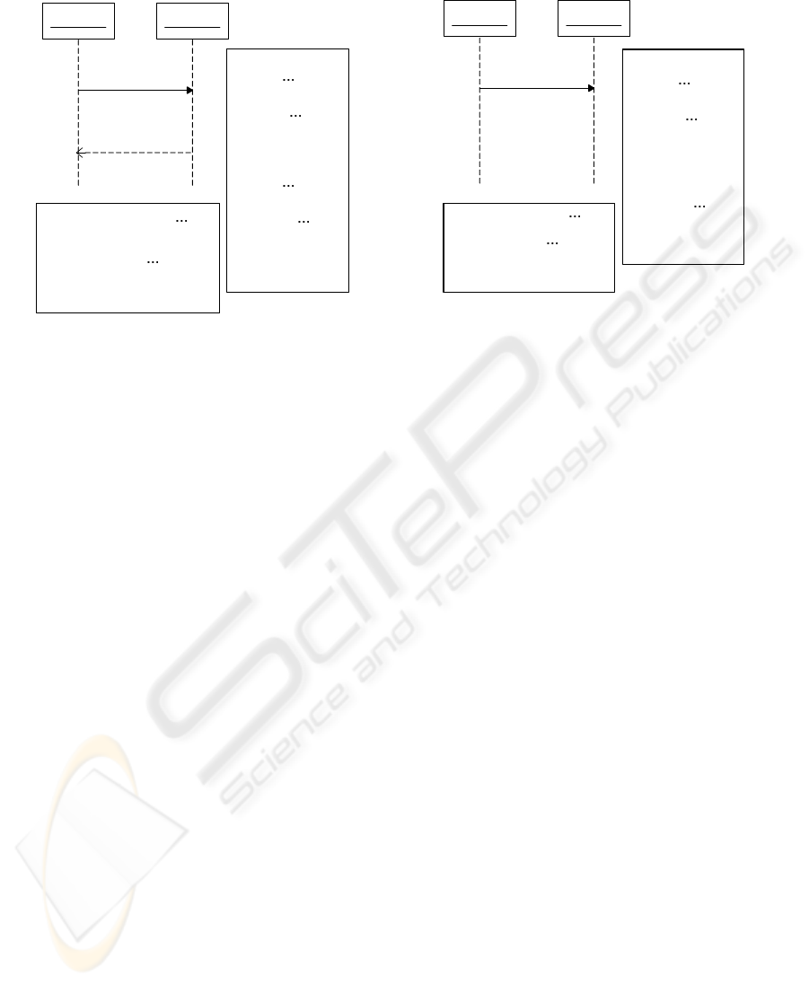
defined by the “proctype” statement. For example, a
message m from “Object 1” to “Object 2 with the re-
turn message r, which is denoted as r = m(x
1
, ··· , x
m
),
can be expressed as shown in Figure 1 (a). In this
figure, X
i
and R represents the data types of x
i
and r
respectively. On the other hand, “chM” and “chR”
represent the channels for m and r respectively.
II-2. Asynchronous Message. Unlike a synchronous
message, a sender lifeline of an asynchronous mes-
sage does not wait for the return message. Such mes-
sage can be implemented in Promela as a simple mes-
sage sending as.shown in Figure 1 (b).
II-3. Creation Message. A creation message cre-
ates instantiates an object. The operation name on
the message represents the constructor of the object.
Since an object is represented as a process designated
by a “proctype” statement, this message can be im-
plemented as a “run” statement for the process that
represents the object to be created. In this process,
the message is received through the channel for it in
the same way as a synchronous or an asynchronous
message.
II-4. Lost Message and Found Message. A lost
message is a message that is sent outside the model
boundary, and therefore onlythe sender lifeline exists.
Such message is expressed in Promela as a sender
channel without the corresponding receiver channel.
The sender process sends the message using “chM !
x1, c, xm”, however no corresponding “chR ? x1, c
,xn” occurs in the Promela code.
On the other hand, a found message is a mes-
sage that is received from the outside of the model
boundary. Theoretically, such message is expressed in
Promela as a receiver channel without the correspond-
ing sender channel. However, in this implementation,
no process in the Promala code puts the message in
the channel. Therefore a dummy process is needed,
which put the message into the above channel.
The basic control structure of a sequence model
is that all the messages are processed along lifelines
from top to bottom. A combined fragment defines
a special region in a sequence model, which can pro-
vide more complicated control structures such as con-
currency, conditional branches, or iterations. The se-
mantics of a combined fragment is designated by a
tag on the fragment, e.g. par, alt, or loop. According
to these tags, combined fragments can be expressed
by Promela as follows.
III-1. Alternative Fragment. An alternative frag-
ment represents if-then-else control structure, which
is designated by the alt tag. This control structure is
EVALUATING UML SEQUENCE MODELS USING THE SPIN MODEL CHECKER
419
Object 1 Object 2
r
proctype Object1() {
X1 x1;
; Xn xn
R r;
chm ! x1,
,xn;
chr1 ? x;
{
proctype Object2() {
X1 x1,
, Xn xn;
R r;
chm1 ? x1,
,xn;
inlineM();
chR1 ! r1;
{
chan chM1 [0] of {X1,
,Xn}
chan chR [0] of {R}
inline inlineM(x1,
,xn) {
code for message m
{
m(x1, ... ,xn)
Object 1 Object 2
m(x1, ... xn)
proctype Object1() {
X1 x1;
; Xn xn
R r;
chm ! x1,
,xn;
{
proctype Object2() {
R r;
chm1 ? x1,
,xn;
inlineM();
{
chan chM [0] of {X1,
,Xn}
inline inlineM(x1,
,xn) {
code for message m1
{
(a). Synchronous Message (b). Asynchronous Message
Figure 1: Sequence Model and Promela Code – 1.
expressed by a Promela if - fi block with else clause.
III-2. Option Fragment. An option fragment rep-
resents a simple if-then, which is designated by the
opt tag, and can be regarded as a special case of a alt
fragment.
III-3. Loop Fragment. A loop fragment represents
an iterative process, which is designated by the loop
tag. This control structure is expressed in Promela by
do - od block.
III-4. Parallel Fragment. A parallel fragment con-
sists of multiple regions each of which represents
a message passing operation concurrently performed
with other regions. This fragment is designated by
the par tag. For expressing concurrency, each region
in the fragment must be transformed into a Promela
code independently. As a result, for each region, a
process is defined per lifeline involved in the region .
III-5. Break Fragment. A break fragment, which
is designated by break tag, terminates the process de-
fined in its outer fragment. This fragment is invoked
only when the associated guard function is satisfied.
The fragment is implemented using a boolean vari-
able, e.g. “bch, which represents the break condition.
The variable “bch is initially set to false, and is set to
true in the break fragment. The do statement of the
outer fragment examines whether “bch is false.
III-6. Critical Fragment. A critical fragment repre-
sents that the fragment must be performedas a critical
section, that is, no interruption is allowed when it is
active. This fragment is usually used as a part of a
⁀
par
fragment, and is designated by the critical tag. The
fragment can be implemented using a boolean vari-
able, e.g., “lock;”, for a locking mechanism. At the
first statement in the critical fragment, the lock is set
to true, while at the last statement, the lock is set to
false On the other hand, the variable “lockh is exam-
ined in the outer fragments tha conflict with the criti-
cal fragment.
III-7. Weak Sequencing Fragment. In a weak se-
quencing fragment, which is designated by seq tag,
defines the ordering of messages as follows.
1. The ordering of OccurrenceSpecifications within
each of the operands are maintained in the result.
2. OccurrenceSpecifications on different lifelines
from different operands may come in any order.
3. OccurrenceSpecifications on the same lifeline
from different operands are ordered such that
an OccurrenceSpecification of the first operand
comes before that of the second operand.
In this fragment, the order of any two messages reside
in the different segments on the different lifelines may
not be maintained. In order to implement this con-
siderably complicated combined fragment type, we
introduce an indicator variable “l
i
h for each lifeline,
and “s
j
h for each segment. The “l
i
h represents the
number of received messages by the ith lifeline, while
“s
j
h represents that of the jth segment. In addition,
the ordering constraints are appended to each mes-
sage sending statement.
IV. Execution Occurrence. An execution oc-
currence represents that a lifeline or the correspond-
ing object is performing some functionality. This
model element also represents the method execution
within the object, and is expressed in a Promela code
ICEIS 2010 - 12th International Conference on Enterprise Information Systems
420

as an inline macro that reflects the method specifica-
tion.
V. State Invariant. This model element can be
put at an arbitrary point on a lifeline in order to spec-
ify the constraints to be satisfied at the point it is
placed. This element is used to create the LTL for-
mula against which the transformed Promela code
from the sequence model is to be evaluated.
By means of the above transformation rules, we
can obtain a Promela code that reflects the semantics
of a given UML sequence model. This Promela code
can be examined by the SPIN model checker whether
it satisfies the necessary constraints if they are given
correctly in the form of LTL formulae. In the next sec-
tion, we discuss how these LTL formulae are derived
from the sequence model.
4 EXTRACTING THE LTL
FORMULAE
As discussed above, state invariantsrepresent the con-
straints on a sequence model, and therefore they could
be the criteria of the correctness for the model. In
order to use the state invariants as the criteria of the
correctness in the SPIN model checker, they must be
expressed in the form of LTL formulae.
Since time flows along the lifelines from top to
bottom, if state invariants P
1
, ··· , P
n
are located out-
side combined fragments from top to bottom, the LTL
formulae P
i
→ ♦P
j
for all i < j must be satisfied
3
.
On the other hand, if state invariants are placed
within a combined fragment, the vertical order of the
state invariants do not represents the temporal order.
The LTL formulae derived from those invariants de-
pend on the fragment types to which they belong.
Generalized rules for each fragment type are as fol-
lows.
A. alt Fragment. An alternative fragment includes
multiple regions each of which is associated with a
guard. Assuming there is a state invariant P above an
alt fragment, and within the fragment, there are n re-
gions R
1
, . . . , R
n
which are associated with the guards
G
1
, . . . , G
n
and the state invariants S
1
, . . . , S
n
, the de-
rived LTL formula would be
P → ♦
(G
1
→ ♦S
1
) ∨ ···(G
n
→ ♦S
n
)
If no invariantis associated with the region R
i
, the cor-
responding term G
i
→ ♦S
i
is removed from the above
formula.
3
, and ♦ mean generally and finally of the temporal
logic respectively
Similarly, if a state invariant Q is located below
the alt fragment, the derived LTL formula would be
(S
1
→ ♦Q) ∨ ··· ∨ (S
n
→ ♦Q)
B. opt Fragment. An opt fragment can be regarded
as a special case of alt fragment, which includes only
one region R with a guard G and an invariant S. For
the above P and Q, the following LTL formulae would
be derived.
P → ♦(G → S)
(S → ♦Q)
C. loop Fragment. A loop fragment iterates a pro-
cess while the associated guard is true. Assuming
state invariants P and Q are located above and bel-
low the fragment respectively, and a guard G and a
state invariant S are associated with the fragment, the
following LTL formula
P → ♦
(G → ♦S) ∧ (¬G → ♦Q)
D. break Fragment. A break fragment terminates
the outer fragment to which it belongs, when the as-
sociated guard is satisfied. Assuming P and Q are the
state invariants above and below the fragment with
the guard condition G and the state invariant S, the
derived LTL formula would be
P → ♦(G → ♦S)
∧
(G → ♦S) → ♦Q
E. par Fragment. A par fragment represents a con-
current execution of multiple processes, and there-
fore there could be multiple states within the frag-
ment. Assuming P and Q are the state invariants
located above and below it respectively, and there
are n concurrent regions including the state invari-
ants S
1
, . . . , S
n
respectively, the derived LTL formulae
would be
(P → ♦S
1
) ∧ ··· ∧ (P → ♦S
n
)
(S
1
→ ♦Q) ∧ ··· ∧ (S
n
→ ♦Q)
F. critical Fragment. A critical fragment halts all
other regions within the par fragment to which the
critical fragment belongs. Since this fragment repre-
sents a microscopic control flow in a sequence model,
and LTL formula deals with more macroscopic state
transitions, LTL is not suitable to this fragment type.
In order to discriminate this fragment type, we need
to n boolean flags a
1
, . . . , a
n
for concurrent n regions
within the par fragment, which are to be turned on/off
every time the regions perform something. Assuming
a
1
is the flag for the critical region, and P is a state in-
variant above the par fragment, the derived LTL for-
mula would be
P → ¬♦
a
1
∧ (a
2
∨ ··· ∨ a
n
)
EVALUATING UML SEQUENCE MODELS USING THE SPIN MODEL CHECKER
421

where a
i
means a
i
== true.
G. seq Fragment. This fragment type also expresses
a microscopic control structure similarly to the above
critical fragment. As discussed in the previous sec-
tion, some messages may be processed in reverse or-
der. In order to express the order of messages in LTL
formula, we introduce boolean flags for each message
that might be processed in reverse order. For example,
assuming m
1
and m
2
are the boolean flags, and P is a
state invariant located above the fragment, the derived
LTL formula would be
P →
(m
1
→ ♦m
2
) ∧ (m
2
→ ♦m
1
)
While the above discussed transformation rules
can derive LTL formulae from the state invariants
within UML sequence models, there is another set
of constraints, that is, pre- and post-conditions of the
methods which are implicitly referred to every time a
message is sent to a lifeline. A method within an ob-
ject is invoked when a message reaches a lifeline, and
terminates when a return message is sent back, in the
case of a synchronous message. Since the pre- and
post-conditions are the constraints that must be satis-
fied before and after the method execution, they can
be regarded as state invariants at the above two points
on a lifeline.
Once the pre- and post-conditions are placed as
state invariants at the appropriate points on lifelines,
we can derive the LTL formulae using the above trans-
formation rules.
5 CONCLUSIONS
We have presented a formal approach to evaluating
the correctness of UML sequence models using the
SPIN model checker. In this approach, we first re-
veal the basic structure of a sequence model based
on a state transition viewpoint, since the SPIN can
only treat state based systems expressed in the form
of Promela codes.
In order to make a sequence model possible to be
examined by the SPIN, a set of transformation rules
was introduced, which could derive Promela codes
from a given sequence model. These rules were de-
fined for each model element of a sequence diagram.
In addition, the criteria of the correctness of a se-
quence model have been presented. These criteria
were extracted from the state invariants that occur in
the model, or from the pre- and post-conditions of
the methods that corresponded to the messages flow-
ing through the model. The criteria have to be trans-
formed into LTL formulae against which the above
Promela codes are examined by the SPIN. The trans-
formation rules for these LTL formulae were also pre-
sented based on which location the state invariants or
the pre- or post-conditions were marked.
REFERENCES
Ambler, S. (2004). The Object Primer. Cambridge Univer-
sity Press, New York, 3rd edition.
Clarke, E., Grumberg, O., and Peled, D. (1999). Model
Checking. The MIT Press, Cambridge, MA.
Damm, W. and Harel, D. (1998). Lscs: Breathing life into
message sequence charts. In Formal Methods in Sys-
tem Design, pages 293–312.
Holzmann, G. (2003). The SPIN Model Checker: Primer
and Reference Manual. Addison-Wesley Professional.
Knapp, A. and Wuttke, J. (2006). Model checking of uml
2.0 interactions. In Workshops and Symposia at MoD-
ELS 2006, pages 45–51.
Richards, M. and Monson-Haefel, R. (2009). Java Message
Service. O’Reilly Media, Inc.
Shen, H., Virani, A., and Niu, J. (2008). Formalize uml 2
sequence diagrams. In 11th High Assurance Systems
Engineering Symposium, pages 213–219.
ICEIS 2010 - 12th International Conference on Enterprise Information Systems
422
