SHARED MEMORY IN RTAI SIMULINK FOR
KERNEL AND USER-SPACE COMMUNICATION
AT THE EXAMPLE OF THE SDH-2
QRtaiLab For SDH-2 Matrix Visualization
Thomas Haase, Heinz W
¨
orn
Institute for Process Control and Robotics (KIT), Karlsruhe Institute of Technology, D-76131 Karlsruhe, Germany
Holger Nahrstaedt
Control Systems Group, TU Berlin, D-10587, Berlin, Germany
Keywords:
QRtaiLab, RTAI linux, Matlab simulink Real-time workshop, SDH2, Shared memory.
Abstract:
At the Institute for Process Control and Robotics reactive grasping skills are developed to enhance the Multi-
fingered SCHUNK Dextrous Hand 2 (SDH2) in order to fulfill industrial needs. Therefore, RTAI Linux and
Matlab - Simulink RTW are used as application development system (RTAI, 2010),(Mathworks, 2010). The
exchange of data between the Multi-fingered hand and the computer system is possible by means of a C++
library. By reason that this SDH2 C++ library could not be used in Real-Time kernel programs this paper
presents an approach of how to combine Real-Time Simulink models (RTAI) with user-space tasks. Therefore
a shared memory based interface within Simulink S-Functions is established. The RTAI Target Language
Compiler remains unaffected. The designed interface is described in detail. It represents a contribution to the
further development of RTAI. In addition a possibility of how to debug and visualize tactile sensor matrices
with QRtaiLab is presented.
1 INTRODUCTION
The Real-Time Application Interface for Linux
(RTAI) combined with the Matlab/Simulink Real-
Time Workshop offers the possibility to generate C
code from Simulink models. Therefore, RTAI uses
the configurable code generator called Target Lan-
guage Compiler (Quaranta and Mantegazza, 2001).
The resulting C code can be used to run Real-Time
applications within an RTAI patched Linux kernel. It
is not possible to start and to debug the executables
with Simulink. The required interaction with these
Real-Time modules is realized with the help of user
interfaces like QRtaiLab and Xrtailab. At the Insti-
tute for Process Control and Robotics such an RTAI
Real-Time Simulink system was chosen to develop
reactive grasping skills for the SDH2. RTAI was
chosen because the community project RTAI (RTAI,
2010) is up-to-date and offers a Simulink Target
Language Compiler (TLC). In (Quaranta and Man-
tegazza, 2001) a different solution is proposed that
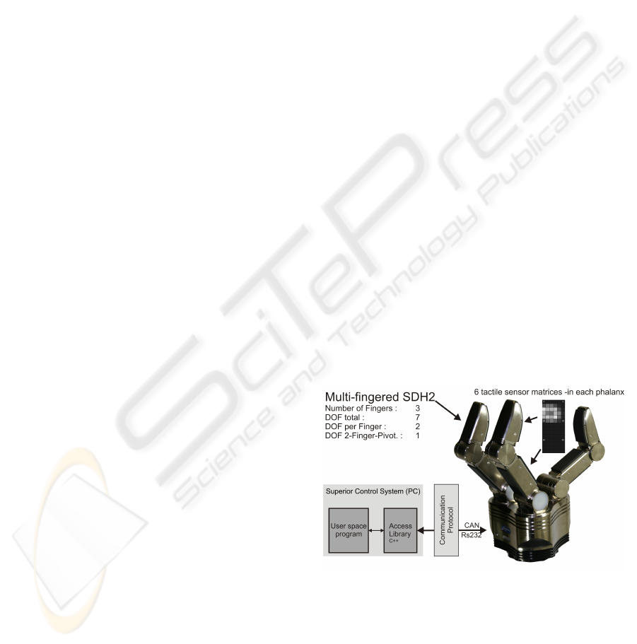
Figure 1: Multi-fingered SDH2.
uses the Tornado/VxWorks Target Language Com-
piler distributed together with MATLAB for creating
the Real-Time code for Linux. Therefore some com-
patibility wrappers to the Simulink VxWorks TLC
interface have to be applied. Unfortunately no user
space communication is mentioned and a new adapted
wrapper has to be built to communicate with the
160
Haase T., Wörn H. and Nahrstaedt H. (2010).
SHARED MEMORY IN RTAI SIMULINK FOR KERNEL AND USER-SPACE COMMUNICATION AT THE EXAMPLE OF THE SDH-2 - QRtaiLab For
SDH-2 Matrix Visualization.
In Proceedings of the 7th International Conference on Informatics in Control, Automation and Robotics, pages 160-165
DOI: 10.5220/0002875401600165
Copyright
c
SciTePress
SDH2. (W.E. Dixon, 2001) and (Ramadurai, 2001)
introduce a Real Time Linux Target (RTLT) as re-
flection to the Real Time Windows Target (RTWT).
RTLT seems to be a software application that gives
Simulink the ability to run on a standard PC with hard
Real-Time constraints. Unfortunately it seems that
further development of RTLT has been stopped sev-
eral years ago. The described computer aided control
system design (CACSD) is only available for RTWT
(D. M. Dawson, 2002).
In 2008 the final version of the Multi-fingered
Dextrous Hand SDH-2 (SCHUNK GmbH & Co. KG,
2010) was introduced, see Figure 1. Each finger pos-
sesses two independent degrees of freedom. Com-
bined with an extra pivoting joint the SDH2 provides
seven degrees of freedom. Six tactile sensor arrays
are included, one in each phalanx. Among others,
they offer the feasibility to detect object contact or
surface characteristics. The data exchange with the
SDH2 is implemented by means of a C++ library.
This library is provided by the manufacturer and is
prepared for working in user space. Unfortunately,
the RTAI Simulink toolbox supports neither a user-
space communication nor a possibility to integrate the
user-space SDH2 C++ library. Therewith, a direct
data exchange among the SDH2 and the Real-Time
executables in kernel space is not possible. In order
to retain the possibility to use RTAI Simulink a way
for exchanging the desired control and sensor data
with these Real-Time programs has to be found. A
universally valid solution is shown in Figure 2. The
data exchange with the SDH2 is not changeable. A
user-space transceiver exchanges all required infor-
mation with the robot hand. A special interface of-
fers these data to the Real-Time executables in kernel
space. The challenge consists of designing an inter-
face that allows the RTAI Target Language Compiler
to remain unaffected. If this will be feasible a con-
tribution to the further development of RTAI can be
achieved. In the following sections an approach of
how to combine Real-Time Simulink models (RTAI)
with user space tasks is presented. Therefore a shared
memory based interface within Simulink S-Functions
is established. Generating named memory in kernel
space is the determining advantage of this inter-task
communication mechanism. Another advantage is,
that there are no data queues and therewith only one
actual dataset is given. This is crucial for transferring
a large amount of tactile sensor data. Both, user-space
program and kernel module, should be able to ad-
dress this allocated memory. The allocation of shared
memory in user-space programs is a well-known op-
eration. In the next sections it is shown how to de-
sign a Simulink S-Function that realizes the access
SDH2
SuperiorControlSystem(PC)
Real-Timekernel
Real-TimeSimulinkmodel
UserSpace
Transceiver
Access
library
UserSpace
Simulink
RTAI.tlc
required
interface
Figure 2: Global Concept of the Required Interface.
and therewith the communication for the Real-Time
executable. This interface enhances the amount of
possibilities in developing (semi-) Real-Time control
systems with Matlab / Simulink using RTAI Linux.
In addition, all RTAI files stay untouched and the
RTAI Target Language Compiler (RTAI.tlc) is used
anymore.
2 THE SHARED MEMORY
INTERFACE
2.1 Basic Concept
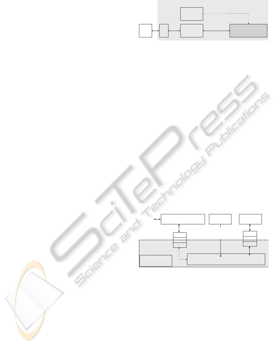
Figure 3 shows the basic concept of the RTAI SDH2
simulation environment. Simulink is used to de-
sign software algorithms. The RTAI Target Lan-
guage Compiler generates the Real-Time code that
could be controlled and debugged with the help of
QRtaiLab / Xrtailab. The Real-Time Simulink code
SimulinkReal TimeCode+Execution
ExternalSoftware
usingSDHC++library
RTAI
Mailbox
RTAI-Real-
Time-Kernel
User-Space
QRTAILab
0.1.7
Simulink
Generate
Real
Code
Control
Program
Flow
Shared
Memory
SDH
RTAIKernelModul
createstherequired
SharedMemory
Figure 3: Concept of SDH-2 RTAI application development
system.
is able to communicate with a shared memory mod-
ule to exchange information and sensor data with the
user-space transceiver module. The development sys-
tem from Figure 3 requires a user-space program that
communicates with the SDH2, an additional kernel
tool for setting up the shared memory and some RTAI
Simulink tools. Furthermore, for constructing and
proceeding Simulink based Real-Time applications, a
patched RTAI Linux kernel and the RTAI toolbox for
Simulink are required. The Target Language Com-
piler (RTAI.tlc) that generates the Real-Time (RTAI)
code from the Simulink models is part of the RTAI
Simulink toolbox(Quaranta and Mantegazza, 2002).
SHARED MEMORY IN RTAI SIMULINK FOR KERNEL AND USER-SPACE COMMUNICATION AT THE
EXAMPLE OF THE SDH-2 - QRtaiLab For SDH-2 Matrix Visualization
161
As mentioned in section 1, it is not possible to exe-
cute and to debug the created Real-Time code with
Simulink itself. All RTAI Simulink modules gener-
ate mailboxes for inter-task communication of all de-
sired measurable signals. The scopes and displays
in Simulink are not able to import the mailbox data.
Therefore, additional software tools like Xrtailab or
QRtaiLab are required to receive and to visualize
measured values. Based on the demand for visual-
ization of tactile sensor matrices, QRtaiLab 0.1.7 or
newer is used instead of Xrtailab and is presented in
section 4.
All required software from Figure 3 is described in
detail within the following sections. It is shown how
to create the SDH2 Simulink S-Function on the basis
of the RTAI Simulink library.
2.2 The RTAI Kernel Module
For being able to access named shared memory in
user-space programs, it has to be created by a Real-
Time task first. This kernel module presented here
creates the shared memory required for the Real-Time
simulations. The common rtai-shm kernel module has
to be loaded into the kernel before this tool is able to
create the memory. As an example, the following enu-
meration shows all the different shared structures that
are desired for working with the SDH2:
1. tactile sensors: to import sensor data from user-
space into kernel-space
2. control: exchange the SDH2 control protocol
3. exporting joint angles into user-space (i.e. simu-
lation)
The generation of the tactile sensor data array is
shown more precisely in Listing 1. Simulink S-
Function, RTAI kernel module and user-space com-
munication software are all using the same structure
’TAK’. The tactile shared memory is generated within
the RTAI kernel module, Figure 3:
1# define SHM _ N a m e " name / ID "
2static RT_TAS K t1 ;
3typedef s t r u c t TAK {
4int M a t r i x 1 [84];
5int M a t r i x 2 [78];
6...
7} MSG _ T A K ;
8...
9r t _ set _ p eri o d ic_m o de () ;
10taktil =
rta i _ kmall o c ( n a m 2 n u m ( SHM_Name ) ,
sizeof ( struct TAK) ) ;
11period = s tart_ r t _tim e r ();
Listing 1: Kernel Module Listing.
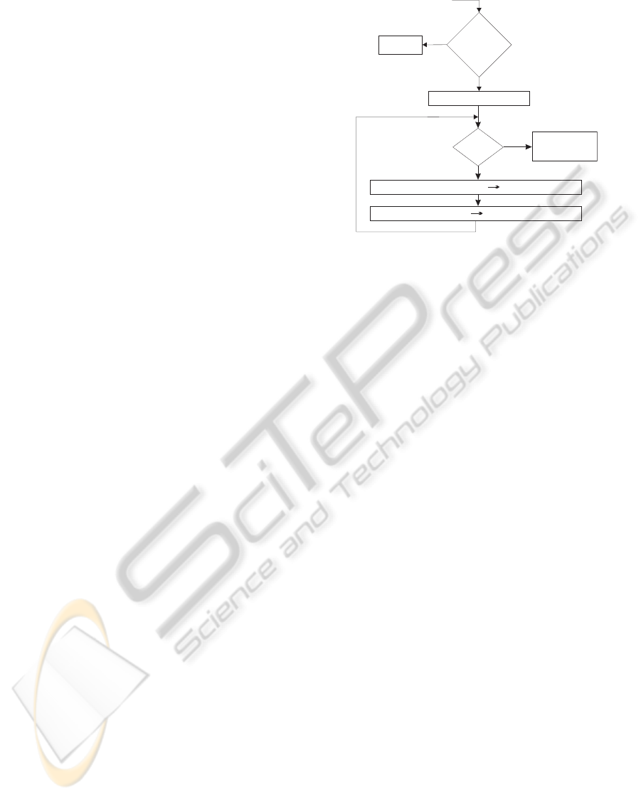
connecttoSDH2
ReadfromSDH-2WriteSHM
closeSDH2
connection
finished
shared
Memory
exist
no
yes
exit
ReadfromSHMWritetoSDH2
yes
no
program
start
Figure 4: Program flow chart of user space software.
The variable “name/ID” is the unique identifier which
allows to access the SHM. The defined struct (Line
3 to 7) contains all required arrays. This RTAI
kernel module creates that named shared memory
“name/ID” in Line 11. Now, all software modules in
kernel- and in user-space are able to access the SHM.
It is recommended that all structures and defines are
swapped out into a shared header file.
2.3 User Space Control Transceiver
The user-space transceiver software from Figure 3 ex-
changes the predefined control and sensor data with
the SDH2. It includes all data to and reads from
the shared memory. Figure 4 illustrates the flow
chart. It is recommended, that the kernel module
from section 2.2 has already created the SHM be-
fore this transceiver is started. The program uses
the C++ SDH2 library in user-space. Unfortunately
this code is not running under Real-Time constraints.
Due to the shared memory the operating speed of
the transceiver is independent from any time scale of
all Simulink Real-Time executables in kernel space.
The program is kept as small as and therewith as fast
as possible to ensure minimal reaction times. Since
the SDH2 uses a CAN or an RS232 interface, the
transceiver reaches the currently maximum possible
operating frequency f
o
with up to f
o
= 60Hz.
3 THE SHARED MEMORY
S-FUNCTION
The goal of this paper is the description of how
to set up RTAI Simulink S-Functions using special
shared memory arrays. The usage of the common
ICINCO 2010 - 7th International Conference on Informatics in Control, Automation and Robotics
162

RTAI Target Language Compiler has to be ensured
without limitations. The basic requirement for each
S-Function is the availability of all shared memory
structures used in kernel space. Required header files
should be integrated into the S-Functions as shown in
listing 2
1# ifndef M A T LAB_ M E X_FI L E
2...
3# i n c lude < rtai _ s h m . h >
4...
5# endif
Listing 2: Integration of header files to allocate shared
memory.
To make sure that the included RTAI modules are only
addressed if working in Real-Time, Simulink defines
MATLAB
−
MEX
−
FILE if working in normal Non-
Real-Time mode.
3.1 Shared Memory Input
The following listing presents an essential abstract of
how to input data from named shared memory into an
RTAI Real-Time executable.
1static void
md l I niti a lize S i zes ( S i m Struct * S){
2if (! ssSe t O utp u tPo r t Dim e nsi o n Inf o
(S ,0 ,& d) ) r e t u r n ;
3if (! ssSe t O utp u tPo r t Dim e nsi o n Inf o
(S ,0 ,1 )) return ;
4}
5static void m d l Start ( Sim S t r uct * S ){
6# ifndef M A T LAB_ M E X_FI L E
7s t a t i c s t r u c t M S G_TAK * msg;
8if (!( msg = rtai _ m al l oc ( n a m 2n u m (
" name / ID " ) , sizeof ( MSG _ T A K ) )) ) {
9printf ( " no sh a r e d m e m o r y " );
10ex it (1) ;}
11ssG e t P Wo r k (S ) [ 0 ]= ( voi d *) msg ;
12# en d i f
13}
14static vo id m d l Ou t p ut s ( S i mS t r uc t *S ,
in t _ T tid ) {
15do u b l e * M1 =
ss G et Ou tp utP o rt Re al Sig n al (S ,0) ;
16do u b l e *i =
ss G et Ou tp utP o rt Re al Sig n al (S ,1) ;
17# ifndef M A T LA B_ ME X _F IL E
18MS G _ I D * msg = ( MS G _ I D
*) ss G et P Wo rk Va lu e (S ,0) ;
19M1 [ i] = msg -> M a t r i x 1 [i ]; // array
20*i = msg -> v a ri a b l e ; // scalar
21# en d i f
22}
Listing 3: RTAI Simulink Input Listing.
The given code snippet in Listing 3 demonstrates an
S-Function with two output ports (lines 2 and 3). The
first output contains a tactile matrix; variable d spec-
ifies the information about the dimensionality of the
output port. The ’mdlStart’ function initializes the
named shared memory “name/ID”. If no matching
shared memory is found the execution of the Real-
Time model is aborted. Otherwise a pointer to the
initialized data structure is stored in the S-Function
PWork vector for being addressable within further
functions (line 11). Function ’mdloutputs’ accesses
this PWork vector and assigns the data to the output
ports. The lines 19 and 20 demonstrate the differ-
ence in assigning arrays and scalars. To make sure
that the shared memory is only assigned within the
Real-Time kernel and not within the Simulink soft-
ware, the code fragment in lines 6 and 17 are neces-
sary. If the S-Function is built as MEX-file with the
mex command, MATLAB
−
MEX
−
FILE is automati-
cally defined. The RTAI Target Language Compiler is
able to handle this code. It is important, that the SHM
Input S-Function accesses to the SHM struct defined
in listing 1.
3.2 RTAI Simulink Output
Writing data into the assigned shared memory is
nearly equal as shown in section 3.1 and is given in
Listing 4.
1static vo id
md l I ni ti al iz eS iz es ( S im S t ru c t *S )
2{ if (! s sS et Nu mI np ut Po rt s (S , 2) )
return ;
3s s S et In pu tP or tW idt h (
S , 0 , d );
4s s S et In pu tP or tW idt h (
S , 1 , 1 );
5}
6static vo id m d l Ou t p ut s ( S i mS t r uc t *S ,
in t _ T tid )
7{
8I n p ut Re al Pt rs Ty pe uP t r s 1 =
ss G et In put P or tR eal S ig nal P tr s (S ,0) ;
9I n p ut Re al Pt rs Ty pe u1 =
ss G et In put P or tR eal S ig nal P tr s (S ,1) ;
10# ifndef M A T LA B_ ME X _F IL E
11MSG_TAK * msg = ( M S G _ TA K
*) ss G et P Wo rk Va lu e (S ,0) ;
12msg -> P1 = ( do u b l e ) * uP t r s 1 [0];
13msg -> P7 = ( do u b l e ) * uP t r s 1 [6];
14msg -> M ove = ( do u b l e ) * u1 [0];
15msg -> Vari a b l e = 4;
16# en d i f
Listing 4: RTAI Simulink Output Listing.
MdlStart allocates the named shared memory and
stores a pointer to it within the PWork vector. If run-
ning in Real-Time kernel, ’Matlab
−
Mex
−
File’ is not
defined and lines 11 to 15 are executed. Lines 11 to
SHARED MEMORY IN RTAI SIMULINK FOR KERNEL AND USER-SPACE COMMUNICATION AT THE
EXAMPLE OF THE SDH-2 - QRtaiLab For SDH-2 Matrix Visualization
163
14 demonstrate how to assign values to certain shared
variables.
4 QRTAILAB
By means of the Real-Time Workshop (RTW) and the
RTAI Target Language Compiler it is possible to cre-
ate Real-Time C Code from Simulink models. As
mentioned in section 2.1, Simulink is not able to ex-
ecute and to debug the models. Instead of Simulink,
QRtaiLab is able to start, to control and to debug the
generated code. The open source software QRtaiLab
offers nearly the same functionality as Xrtailab. Xr-
tailab is provided through RTAI-Lab, which is a com-
ponent of RTAI. Mailboxes are used as inter-task
communication. This realizes an exchange of data
with the Real-Time Code. In addition it is possible
to display and to log the control data. As Xrtailab
uses the cross-platform C++ GUI toolkit (EFLTK),
there was a need for reprogramming the software us-
ing QT4 (cross-platform application and UI frame-
work). The problem was that EFLTK is not under ac-
tive development and offers only limited functional-
ity. EFLTK must be compiled and installed manually
and needs a manually compiled Mesa-library. Com-
pared to Xrtailab QRtaiLab is much easier to install
and does not use OpenGL, which results in reduced
hardware requirements. QRtaiLab also offers some
additional features:
• saving / loading of block parameters
• auto scaling for scope signals
• visualization of small matrices
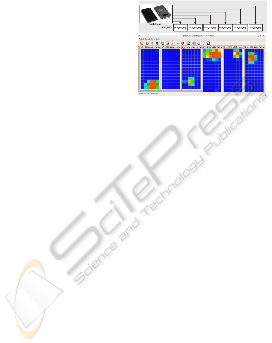
The last feature may be used to verify tactile sensor
matrices from the SDH2. During the development of
tactile reactive grasping skills, it is essential to visual-
ize these matrices. QRtaiLab offers this visualization
by using existing mailbox algorithms within the RTAI
library. A Matrix is transferred to QRtaiLab using the
“RTAI
−
Log” - block from the original RTAI library,
Figure 5. Based on the large amount of data within
each tactile sensor matrix and the limited data trans-
mission the maximum size of a matrix is restricted to
[15 × 10].
5 HOW TO CONFIGURE AND
START A SDH-2 REAL-TIME
SIMULINK MODEL
To create and run a Simulink model as Real-Time
model in RTAI kernel it’s necessary to take the fol-
Figure 5: Visualization of tactile sensor matrices with QR-
taiLab.
lowing steps.
1. activate RTAI kernel: insert kernel modules
2. generate the desired named shared memory (sec-
tion 2.2)
3. create a Simulink model, configure the model for
RTAI Real-Time simulation:
• edit solver: fixed step size (e.g. 5ms), discrete
(no continuous states)
• Real-Time Workshop: Target selection: rtai.tlc
• use normal and not external mode
4. integrate the designed S-Functions from section
3.1 and 3.2 to connect and communicate with the
shared memory
5. generate required C-Code for Real-Time kernel
→(tools/real time workshop/build model)
6. open the current Matlab directory and start the ex-
ecutable (e.g. → ./modelXY -v -w )
7. start user space transceiver software to communi-
cate with the SDH2
8. start QRtaiLab; connect to target and start the sim-
ulation
6 CONCLUSIONS AND FUTURE
WORKS
Working with RTAI Simulink is quite different to
working with Real-Time Simulink on Windows us-
ing xPC or Real-Time Windows Target. Installing
and establishing an RTAI Linux is time-consuming.
Unfortunately Simulink may not be used to execute
and debug the created Real-Time models. There-
fore, additional software is required. The possibili-
ties with regard to the RTAI kernel configurations are
ICINCO 2010 - 7th International Conference on Informatics in Control, Automation and Robotics
164
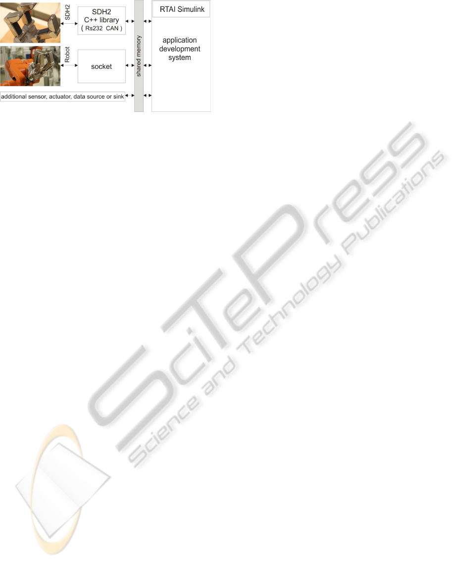
Figure 6: SHM Simulink Inter Task Communication.
very powerful. The realized data exchange enables
software engineers to expand their Simulink models
and to build up control systems for all available hard-
ware, Figure 6. User-defined protocols may be de-
signed to minimize the amount of information. Even
the integration of kernel and user-space sockets into
Real-Time models is feasible (Kiszka, 2004). The
implementation of shared memory is very efficient.
Within a short time it is possible to expand the trans-
ferred data set, to establish new named SHM and to
adapt the required Simulink S-Functions. Addition-
ally it is possible to create S-Functions which are able
to read and write to some shared memory. Even the
access to different SHM in one S-Function is feasi-
ble. Up to now it was possible to run different Real-
Time executables at the same time on one system.
With this presented SHM interface it is now possible
to communicate and exchange data between different
Real-Time modules. Each module and each commu-
nication can be constructed and designed within the
Simulink environment. The design of parallel and
distributed systems with Simulink becomes possible.
The SHM interface is very stable and guarantees a
high degree of operational reliability. The presented
Simulink model of figure 5 is an example application
of the designed SHM interface. High accessing fre-
quencies f
a
of f
a
> 1kHz can be achieved without
difficulty. Application crashes (QRtaiLab, User-space
transceiver, Real-Time executable) do not influence
the interface.
All in all the realized Real-Time-Simulink seems to
be more comprehensive than RTWT. This, however,
is countered by a longer training period.
6.1 Future Works
In the near future it should be possible to commu-
nicate with the SDH2 even in kernel space. There-
fore, an extension of the SDH2 C++ library is nec-
essary. Aside from the facts that the sampling rate
could be increased and that no additional software
will be required for working with the robot hand, it
could even facilitate the working environment. RTAI
Simulink uses mailboxes for inter-task communica-
tion. This paper shows how to use shared memory.
Perhaps shared memory is more suitable to transfer
time-critical information particularly with regard to
matrices. Raising time delays because of growing
message queues are unfeasible. This will be essen-
tial if a large amount of data has to be transferred.
While working on reactive grasping skills it will be
necessary to debug different evaluation algorithms.
Especially for large tactile matrices the mailbox com-
munication becomes unusable. It was shown in sec-
tion 4 that the maximum size of a matrix is restricted
to [15 × 10]. Maybe the usage of shared memory is
able to solve the problem. Furthermore, the assem-
bling of own SHM-based Simulink scopes is consid-
erable. That is based on the fact that the usage of
external software to debug the Real-Time Simulink
models slows down the developing work.
ACKNOWLEDGEMENTS
This project is supported by SCHUNK GmbH & Co.
KG, Lauffen.
REFERENCES
D. M. Dawson, W. D. (2002). Matlab-based control systems
laboratory experience for undergraduate students: to-
ward standardization and shared resources.
Kiszka, J. (2004). Real-time ethernet on top of rtai. Tech-
nical report, University of Hannover, ISE - Real Time
Systems Group, Germany. www.rts.uni-hannover.de.
Mathworks (2010). Generate c code from
simulink models and matlab code.
http://www.mathworks.com/products/rtw/.
Quaranta, P. and Mantegazza, P. (2001). Using matlab
simulink rtw to build real-time control applications in
user space with rtai-lxrt. Technical report.
Quaranta, P. and Mantegazza, P. (May 27 2002). Interfac-
ing linux rtai with matlab and simulink through real
time workshop. Technical report, University of Ap-
plied Sciences of Southern Switzerland (SUPSI), Dept.
of cs and ee (DIE).
Ramadurai, S. (2001). Using real time linux target to com-
pile and execute a simulink program. Technical report,
Clemson University, Intelligent Systems.
RTAI (2010). The realtime application interface for linux
from diapm. https://www.rtai.org.
SCHUNK GmbH & Co. KG (2010). Servo-electric 3-finger
gripping hand sdh. http://www.schunk.com.
W. E. Dixon, D. M. D. (2001). Towards the standardization
of a matlab-based control systems laboratory experi-
ence for undergraduate students. Technical report.
SHARED MEMORY IN RTAI SIMULINK FOR KERNEL AND USER-SPACE COMMUNICATION AT THE
EXAMPLE OF THE SDH-2 - QRtaiLab For SDH-2 Matrix Visualization
165
