
A MORPHING WING USED SHAPE MEMORY ALLOY
ACTUATORS NEW CONTROL TECHNIQUE WITH
BI-POSITIONAL AND PI LAWS OPTIMUM COMBINATION
Part 2: Experimental Validation
Teodor Lucian Grigorie, Andrei Vladimir Popov, Ruxandra Mihaela Botez
École de Technologie Supérieure, Montréal, Québec H3C 1K3, Canada
Mahmoud Mamou, Youssef Mébarki
National Research Council, Ottawa, Ontario K1A 0R6, Canada
Keywords: Morphing Wing, Shape Memory Alloy Actuators Control, Experimental Validation, Bench Test, Wind
Tunnel Test.
Abstract: The paper represents the second part of a study related to the development of an actuators control system for
a morphing wing application, and describes the experimental validation of the control designed in the first
part. After a short presentation of the finally adopted control architecture, the physical implementation of
the control is done. To implement the controller on the physical model two Programmable Switching Power
Supplies AMREL SPS100-33 and a Quanser Q8 data acquisition card, were used. The inputs of the data
acquisition were two signals from Linear Variable Differential Transformer potentiometers, indicating the
positions of the actuators, and six signals from thermocouples installed on the SMA wires. The acquisition
board outputs channels were used to control power supplies in order to obtain the desired skin deflections.
The control validation was made in two experimental ways: bench test and wind tunnel test. All 35
optimized airfoil cases, used in the design phase, were converted into actuators vertical displacements which
were used as inputs reference for the controller. In the wind tunnel tests a comparative study was realized
around of the transition point position for the reference airfoil and for each optimized airfoil.
1 INTRODUCTION
The spectacular and continuous evolution of the
aerospace engineering domain was highlighted in
the last years especially through the boarded
equipments and systems technology development,
mainly those of avionics. But, in the same time, the
two related sub-domains, propulsion systems and
aircraft structures, in parallel registered very
important discoveries, sometimes notified to the
general public too little. Thus, the concept of green
aircraft launched major trends in the aerospace field
research, of which can be mentioned reduction of
noise and chemical pollution of the atmosphere,
reduction of fuel consumption and increase of
aircraft flight autonomy. This concept is a
consequence of the predictions for future according
with that the air traffic is seen to more than double in
the next 20 years. Therefore, both environmental and
economic pressures will strongly increase and
significant progress will need to be achieved in both
improving the efficiency and minimizing the
environmental impact of aircraft. In order to provide
these required changes, aircrafts in new concepts are
designed and will be developed. These suppose the
validation and after that the integration of new
technologies and solutions at the level of all major
aircraft components: cabin, wing, power plant
system, and fuselage; multidisciplinary
investigations already explore the different
associated aspects of aero-dynamics, acoustics,
materials, structure, engines and systems. The aims
of these investigations are to ensure an improved
quality and affordability, whilst meeting the
tightening environmental constraints (emission and
noise), with a vision of global efficiency of the air
13
Lucian Grigorie T., Popov A., Mihaela Botez R., Mamou M. and Mébarki Y. (2010).
A MORPHING WING USED SHAPE MEMORY ALLOY ACTUATORS NEW CONTROL TECHNIQUE WITH BI-POSITIONAL AND PI LAWS OPTIMUM
COMBINATION - Part 2: Experimental Validation.
In Proceedings of the 7th International Conference on Informatics in Control, Automation and Robotics, pages 13-19
DOI: 10.5220/0002878500130019
Copyright
c
SciTePress

transport system.
Within this context are developed our research
related to the morphing aircraft new challenge field,
precisely to the morphing wing concept in this field
(Chang, 2009, Smith, 2007, Hinshaw, 2009,
Gonzalez, 2005, Namgoong, 2006, Majji, 2007, and
Ruotsalainen, 2009). The presented work objective
is to develop an actuation control concept for a new
morphing mechanism using smart materials, like
Shape Memory Alloy (SMA), as actuators. These
smart actuators modify the upper surface of a wing
made of a flexible skin so the laminar to turbulent
transition point moves close to the wing airfoil
trailing edge. The final purpose of the research
project is to obtain a drag reduction as a function of
flow condition, by changing the wing shape.
The chosen wing model was a rectangular one,
with a reference airfoil WTEA-TE1, a chord of 0.5
m and a span of 0.9 m. The model was equipped
with a flexible skin made of composite materials
morphed by two actuation lines. Each actuation line
uses shape memory alloys wires as actuators.
In the first part of this paper a control for the
actuation lines of the morphing wing system was
designed. In this way, 35 optimized airfoils available
for 35 different flow conditions (five Mach numbers
(0.2 to 0.3) and seven angles of attack (-1˚ to 2˚)
combinations) were used.
From the developed actuation mechanism results
that each actuation line uses three SMA wires (1.8 m
in length) as actuators, and contains a cam, which
moves in translation relative to the structure (on the
x-axis in Fig. 1). The cam causes the movement of a
rod related on the roller and on the skin (on the z-
axis). The recall used is a gas spring. The horizontal
displacement of each actuator is converted into a
vertical displacement at a rate 3:1, which makes that
the horizontal stroke of x mm to be converted into a
vertical stroke z=x/3; results a cam factor c
f
=1/3,
therefore, for the approximately 8 mm maximum
vertical displacement, obtained from the optimized
airfoils numerical data, a 24 mm maximum
horizontal displacement must be actuated.
HeatingCooling
Three SMA wires
Flexible skin
Cam
Roller
Support plate for
actuation system
Rod
Compression
spring
x
z
Figure 1: The actuation mechanism concept.
The designed controller controls the SMA
actuators in terms of supply electrical current so that
to cancel the deviation between the required values
for vertical displacements (corresponding to the
optimized airfoils) and the real values, obtained
from two position transducers (Fig. 2).
, M,
Re
Pilot
Control
Flight
conditions
Optimised
airfoils
database
dY
1opt
dY
2opt
Real airfoil
Integrated
controller
dY
1real
dY
2real
SMA
actuators
e=dY
opt
- dY
real
Airflow
perturbations
Current
Position
transducers
dY
1real
dY
2real
Figure 2: Operating schema of the SMA actuators control.
The finally numerical validated configuration (in
the first part of the paper) of the integrated controller
was a combination of a bi-positional controller
(particularly an on-off one) and a PI (proportional-
integral) controller, due to the two phases (heating
and cooling) of the SMA wires interconnection. The
resulted controller must behave like a switch
between cooling phase and heating phase, situations
where the output current is 0 A, or is controlled by a
law of PI type
.0if,d)(0061.787)(8.1792
,0if,0
)(
ettete
e
ti
(1)
e is the operating error (see Fig. 2).
2 PHYSICAL MORPHING WING
CONTROL IMPLEMENTATION
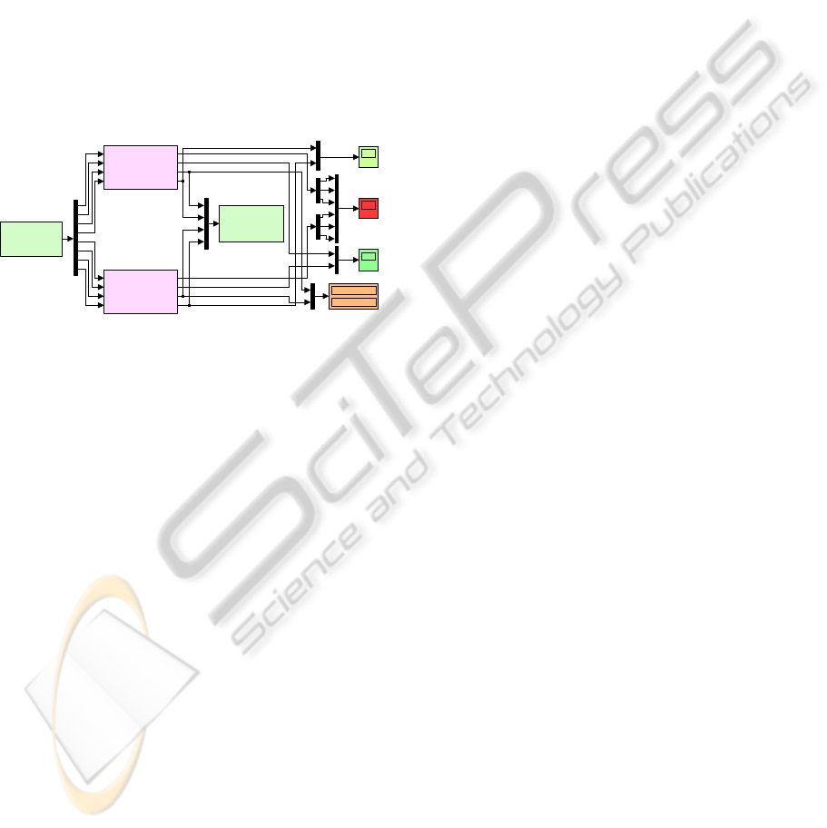
Starting from the theoretical and numerical
simulation resulted considerations to implement the
controller on the physical model two Programmable
Switching Power Supplies AMREL SPS100-33,
controlled by Matlab through a Quanser Q8 data
acquisition card, were used (Fig. 3) (Kirianaki, 2002,
Park, 2003, and
Austerlitz, 2003).
dY
1
dY
2
SMA#1 SMA#2
.
.
.
pressure sensors
Optimum
airfoil
Reference airfoil
Desired
dY
1
, dY
2
Analog output signal for
power supply control
AMREL SPS100-33
power supplies
Position
transducers
Quanser Q8 data
acquisition card
Analog input signal
from position
transducers
Real
dY
1
, dY
2
Figure 3: Physical model operating schema.
ICINCO 2010 - 7th International Conference on Informatics in Control, Automation and Robotics
14
The power supplies have RS-232 and GPIB
IEEE-488 as standard features and the technical
characteristics: Power 3.3kW, Voltage (dc) 0÷100
V, Current (dc) 0÷33 A. The Q8 data acquisition
card has 8 single-ended analog inputs with 14-bit
resolution. All 8 channels can be sampled
simultaneously at 100 kHz, with A/D conversion
times of 2.4 µs/channel, simultaneous sampling and
sampling frequencies of up to 350 kHz for 2
channels. Also, the Q8 card is equipped with 8
analog outputs, with software programmable voltage
ranges and simultaneous update capability with an 8
µs settling time over full scale (20V).
The acquisition board was connected to a PC and
programmed through Matlab/Simulink R2006b and
WinCon 5.2 (Fig. 4).
0
Volts
Temp
StartVolt
termocouple1
termocouple2
termocouple3
position 2
temp
amps
control V
start 5V
SMA2
termocouple1
termocouple2
termocouple3
position 1
temp
amps
control V
start 5V
SMA1
Q8
Quanser
Analog Output
Q8
Quanser
Analog Input
Amps
Analog Input
Analog Output
0
Figure 4: Simulink actuators control.
The input signals were two signals from Linear
Variable Differential Transformer potentiometers
that indicate the positions of the SMA actuators, and
six signals from thermocouples installed on all the
SMA wires components. The acquisition sampling
time was set to 0.01 second. The outputs channels of
the acquisition board were used to control each
power supply through analog/external control by use
of a DB-15 I/O connector. The current supplied to
the actuator was set to be limited at 10 A, and the
control signal was set to be 0÷0.6061V (maximum
voltage for the power supply is 2 V for 33 A current
supply).
The operation principle of the physically
implemented controller is relative simple. The initial
input, which is the optimized airfoil for any flow
condition, is chosen manually by the operator from
the computer database through a user interface. Then
the displacements (dY
1
, dY
2
) that are required to be
reproduced by the two control points on the flexible
skin are sent to the controller. This controller sends
an analog signal 0 – 2 V to the power supply that
provides a current to the SMA. The SMA will
respond accordingly and change its length according
to the temperature of the wire. This will result in a
change of the actuators positions, which are sensed
by the linear variable differential transducer
(LVDT). The signal position received from the
LVDT is compared to the desired position and the
error obtained is fed back to the controller. If the
realized position is greater than the desired position
the controller will disconnect the control current
letting the SMA wire to cool down. During the
cooling down process the SMA will maintain its
length due to the hysteretic behavior. This effect is
taken into account for actuators displacement. Also
the controller uses three thermocouples signals from
each SMA wire to monitor the temperature of the
wires and maintain it below 130˚C, as an upper
limit.
3 SMA ACTUATORS CONTROL
BENCH TEST VALIDATION
The morphing wing system in the bench test runs is
shown in Fig. 5.
The gas springs that maintain the SMA wires in
tension had a preloaded value of 225 lbs (1000 N)
since in the laboratory condition there is no
aerodynamic force.
After an initial calibration test the calibration
gains and constants were established for the two
LVDT potentiometers and for the six thermocouples.
The calibration test for LVDT potentiometers
consisted of several scans of airfoil using a laser
beam. On the calibration, the SMA actuators were in
“zero setting position” with no power supplied and
the skin coordinates were measured using the laser
beam that scanned the center line of the wing model.
The laser was set to scan the chord of the model on a
370 mm length with a speed of 5 mm per second.
In the bench test, the 35 optimized airfoil cases
were converted into SMA actuator #1 and #2
vertical displacements which were used as inputs
reference for the controller. A typical test run history
is shown in Fig. 6 for α=1°, Mach=0.3 flight
condition (dY
1
=5.22 mm, dY
2
=7.54 mm – vertical
displacements of the skin in the actuation points).
On observe that the controllers, in the two
actuation lines, work even in zero values of the
desired signal because of the gas springs pretension.
Also, small oscillations of the obtained deflection
are observed around the desired values of the
deflections. The amplitude of the oscillations in this
phase is due to the LVDT potentiometers
mechanical link and to the inertia of the SMA wires,
being smallest than 0.05 mm. The heating phase is
approximately 9 times more rapidly than the cooling
phase; heating time equals 8 s while the cooling time
A MORPHING WING USED SHAPE MEMORY ALLOY ACTUATORS NEW CONTROL TECHNIQUE WITH
BI-POSITIONAL AND PI LAWS OPTIMUM COMBINATION - Part 2: Experimental Validation
15
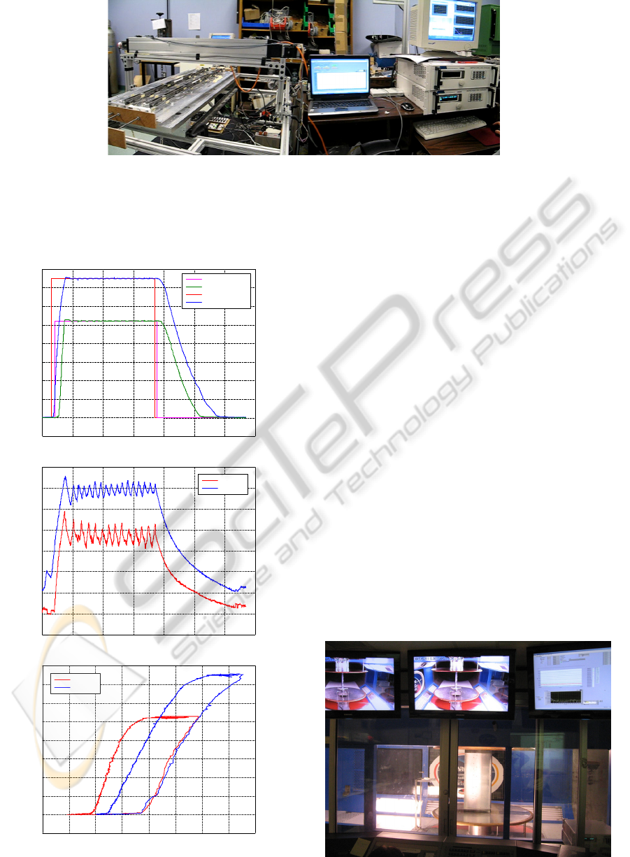
Figure 5: Morphing wing system in the bench test runs.
equals 70 s. There can be observed the differences
between the numerical model of the SMA actuators
and the physical model.
50 100 150 200 250 300 350
-1
0
1
2
3
4
5
6
7
8
0
Time [s]
20
30
40
50
60
70
80
90
100
50 100 150 200 250 300 3500
Time [s]
20 30 40 50 60 70 80 90 100
act #1
act #2
Displacements dY
1
, dY
2
(
v
) [mm]
Temperature [
o
C]
-1
0
1
2
3
4
5
6
7
8
Displacements dY
1
, dY
2
(
v
) [mm]
=1°, Mach=0.3
Temperature [
o
C]
act #1 desired
act #1 obtained
act #2 desired
act #2 obtained
act #1
act #2
Figure 6: Bench test for α=1°, M=0.3 flight condition.
The bench test results confirmed that the
experimental version of the designed integrated
controller woks well even in the lab conditions,
where no aerodynamic forces are loaded and the
preloaded gas springs force is 1000N.
4 SMA ACTUATORS CONTROL
VALIDATION IN WIND
TUNNEL TESTS
Once confirmed the well working of the designed
integrated controller through bench test, the next
step in our morphing wing project was to validate
the controller in a wind tunnel test simultaneously
with the transition point real time detection and
visualization for all 35 optimized airfoils. The model
was tested for all 35 theoretical studied flight
conditions, a comparative study being realized
around of the transition point position for the
reference airfoil and for each optimized airfoil. So,
simultaneously with the controller testing, a
validation study for the aerodynamic part of the
project was realized.
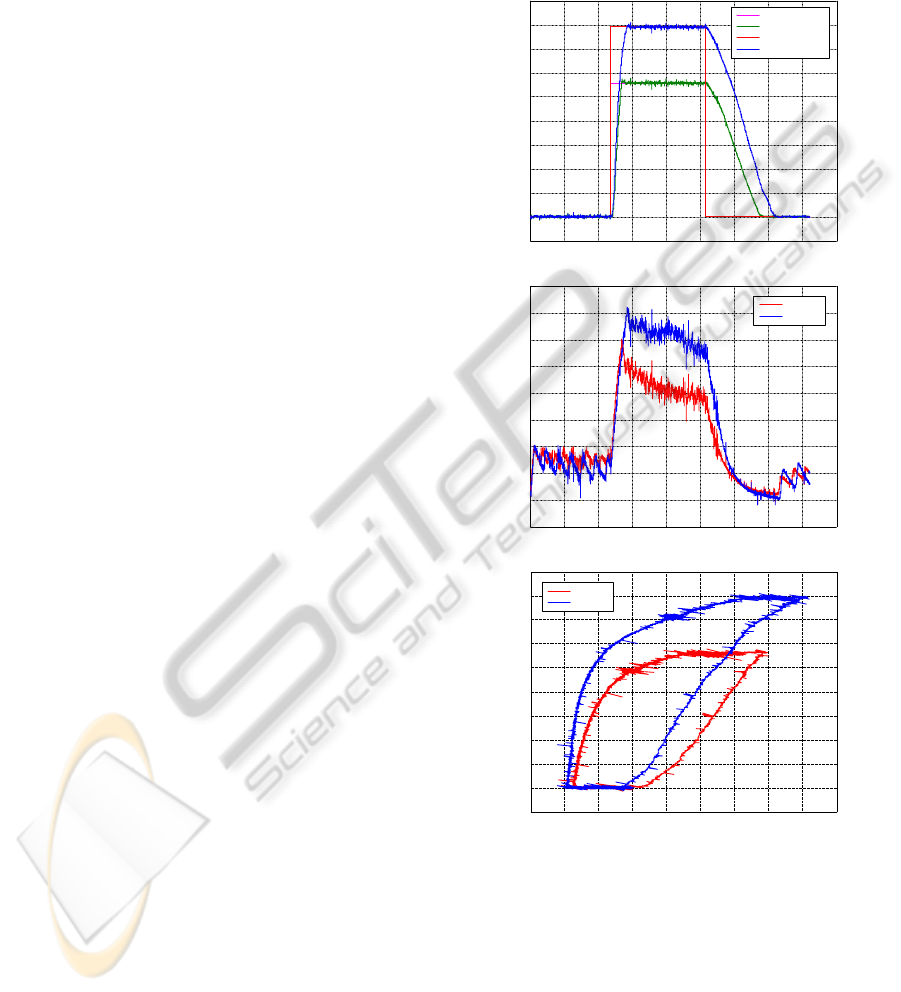
The morphing wing system in the wind tunnel
runs is shown in Fig. 7.
Figure 7: Wind tunnel morphing wing model.
ICINCO 2010 - 7th International Conference on Informatics in Control, Automation and Robotics
16
The transition detection was made real time
using the pressure data obtained from the 32 Kulite
and optical pressure sensors. The pressure data
acquisition was performed using the IAR-NRC
analog data acquisition system which was connected
to the 32 sensors. The sampling rate of each channel
was 15 kS/s, which allowed a boundary layer
pressure fluctuations FFT spectral decomposition up
to 7.5 kHz for all channels. The signal was
processed by use of Simulink and visualized in real
time on the computer screen in dedicated windows.
The pressure signals were analyzed through Fast
Fourier Transforms (FFT) decomposition in order to
detect the magnitude of the noise in the surface air
flow. Subsequently, the data is filtered by means of
high-pass filters and processed by calculating the
Root Mean Square (RMS) of the signal in order to
obtain a plot diagram of the noise in the air flow.
This signal processing is necessary to disparate the
inherent electronically induced noise, by the
Tollmien-Schlichting that are responsible for
triggering transition from laminar flow to turbulent
flow. The measurements showed that in processed
data the transition appeared at frequencies between
3kHz - 5kHz and the magnitude of pressure
variations in the laminar flow boundary layer are of
the order 5e-4 Pa (7.25e-8 psi). The transition
between laminar flow and turbulent flow was shown
by an increase of the pressure variations, reflected
also by a strong variation of the pressure signal
RMS.
For the wind tunnel test the preloaded forces of
the gas springs were reconsidered to the 1500 N
because of the presence of the aerodynamic forces
on the flexible skin of the wing. In Fig. 8 are
presented the control results for test run α=2°,
Mach=0.225 (dY
1
=5.56 mm, dY
2
=7.91 mm).
The experimental results show a decrease of the
SMA wires work temperatures vis-à-vis of
numerically simulated and bench tested cases. An
explanation can be the appearing of the aerodynamic
forces with particular values for each flight
condition. The decrease of these temperatures is a
beneficial one taking into account the negative
impact of a strong thermal field on the other
component of the system, especially on the flexible
skin and on the pressure sensors. Also, from the
experimental results a high frequency noise
influencing the LVDT sensors and the
thermocouples instrumentation amplifiers can be
observed. The noise sources are the wind tunnel
vibrations and instrumentation electrical fields. With
this noise, the amplitude of the actuation error
(difference between the realized deflections and
desired deflections) is under 0.07 mm, but this don’t
affecting the transition, which is stable on a sensor
with a high RMS spike; Fig. 9 presents the results
obtained on the transition monitoring for the run test
in Fig. 8.
20 25 35 40 45 50 55 60
-1
0
1
2
3
4
5
6
7
9
Displacements dY
1
, dY
2
(
v
) [mm]
Temperature [
o
C]
act #1
act #2
30 65
8
20
30
35
40
45
50
55
65
Time [s]
Temperature [
o
C]
act #1
act #2
50 100 150 200 250 300 3500 400
25
60
450
-1
0
1
2
3
4
5
6
7
9
Displacements dY
1
, dY
2
(
v
) [mm]
8
Time [s]
50 100 150 200 250 300 3500 400 450
=2°, Mach=0.225
act #1 desired
act #1 obtained
act #2 desired
act #2 obtained
Figure 8: Wind tunnel test for α=2°, M=0.25 flight
condition.
The actuation line control obtained precision can
have some influence in the transition point position
detection only if the density of the chord disposed
pressure sensors becomes bigger; from the
experimental data evaluation one concluded that,
even the value of the error is 1 mm around the
optimized values, the transition point position on the
airfoil surface is not significantly changed.
A MORPHING WING USED SHAPE MEMORY ALLOY ACTUATORS NEW CONTROL TECHNIQUE WITH
BI-POSITIONAL AND PI LAWS OPTIMUM COMBINATION - Part 2: Experimental Validation
17
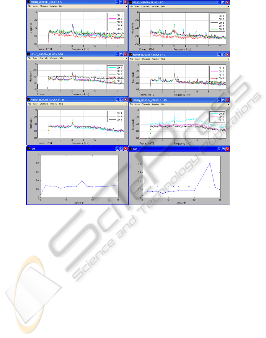
Figure 9: Results obtained on the transition monitoring for the run test in Figure 8.
In Fig. 9 are presented the outputs of the Kulite
pressure sensors in leading edge – trailing edge
sense of positioning (3 sensors are broken and was
not considered in the monitoring phase) and the real
time pressure signals RMS for each of these sensors.
The left hand column presents the results for
reference airfoil, and the right hand column the
results for optimized airfoil. The spike of the RMS
suggests that we have turbulence on the sensor no.
13, near the trailing edge.
So, the results obtained for the actuators control
are very good, the controller fully satisfying the
requirements imposed for the project purpose
achievement.
The future work on the project supposes the
development of the closed loop control, based on the
pressure information received from the sensors and
on the transition point position estimation.
Evidently, the closed loop control will include, as an
internal loop, the actuation lines here presented
controller.
5 CONCLUSIONS
The paper represents the second part of a study
related to the development of an actuators control
system for a morphing wing application, and
describes the experimental validation of the control
designed in the first part. The control validation was
made in two experimental ways: bench test and wind
tunnel test.
In the bench test phase, the 35 optimized airfoil
cases were converted into SMA actuator #1 and #2
vertical displacements which were used as inputs
reference for the controller. The characteristics in
Fig. 6 (α=1°, Mach=0.3 flight condition) show that
the controllers, in the two actuation lines, work even
in zero values of the desired signal because of the
gas springs pretension. Also, small oscillations of
the obtained deflection are observed around the
desired values of the deflections. The amplitude of
the oscillations in this phase is due to the LVDT
ICINCO 2010 - 7th International Conference on Informatics in Control, Automation and Robotics
18

potentiometers mechanical link and to the inertia of
the SMA wires, being smallest than 0.05 mm. The
heating phase is approximately 9 times more rapidly
than the cooling phase; heating time equals 8 s while
the cooling time equals 70 s.
For the final experimental validation test (wind
tunnel test), with real aerodynamic forces load, the
1500 N preloaded forces of the gas springs was
reconsidered. From Fig. 8 (α=2°, Mach=0.225) a
decrease of the SMA wires work temperatures vis-à-
vis of numerically simulated and bench tested cases
is observed. The decrease of these temperatures is a
beneficial one taking into account the negative
impact of a strong thermal field on the other
component of the system, especially on the flexible
skin and on the pressure sensors. Also, a high
frequency noise influencing the LVDT sensors and
the thermocouples instrumentation amplifiers can be
observed. The noise sources are the wind tunnel
vibrations and instrumentation electrical fields. With
this noise, the amplitude of the actuation error
(difference between the realized deflections and
desired deflections) is under 0.07 mm, but this
doesn’t affecting the transition, which is stable on a
sensor with a high RMS spike like in Fig. 9.
So, the results obtained for the actuators control
are very good, the controller fully satisfying the
requirements imposed for the project purpose
achievement.
The designed controller is used for the open loop
development stage of a morphing wing project, but
the closed loop of the morphing wing system, based
on the pressure information received from the
sensors and on the transition point position
estimation, will include, as an internal loop, the
actuation lines here presented controller.
ACKNOWLEDGEMENTS
We would like to thank the Consortium of Research
in the Aerospatial Industry in Quebec (CRIAQ),
Thales Avionics, Bombardier Aerospace, and the
National Sciences and Engineering Research
Council (NSERC) for the support that made this
research possible. We would also like to thank
George Henri Simon for initiating the CRIAQ 7.1
project and Philippe Molaret from Thales Avionics
and Eric Laurendeau from Bombardier Aeronautics
for their collaboration on this work.
REFERENCES
Austerlitz, H., 2003, Data acquisition techniques using
PCs, Elsevier, USA
Chang, P., Shah, A., Singhee, M., 2009, Parameterization
of the Geometry of a Blended Wing Body Morphing
Wing, Project report, Georgia Institute of Technology,
April 2009, Atlanta, Georgia, USA
Gonzalez, L., 2005, Morphing Wing Using Shape Memory
Alloy: a concept proposal, Final research paper, Texas
A&M University, College Station, Texas, USA
Hinshaw, T. L., 2009, Analysis and Design of a Morphing
Wing Tip using Multicellular Flexible Matrix
Composite Adaptive Skins, Master of Science Thesis,
Virginia Polytechnic Institute and State University,
Virginia, USA
Kirianaki, N. V., Yurish, S. Y., Shpak, N. O., Deynega,
V.P., 2002, Data Acquisition and Signal Processing
for Smart Sensors. John Wiley & Sons
Majji, M., Rediniotis, O. K., Junkins, J. L., 2007, Design
of a Morphing Wing: Modeling and Experiments,
AIAA Atmospheric Flight Mechanics Conference and
Exhibit, Hilton Head, South Carolina, USA
Namgoong, H., Crossley, W. A., Lyrintzis, A. S., 2006,
Aerodynamic Optimization of a Morphing Airfoil
Using Energy as an Objective, 44th AIAA Aerospace
Sciences Meeting and Exhibit, Reno, Nevada, USA
Park, J., Mackay, S., 2003, Practical data acquisition for
instrumentation and control systems, Elsevier, UK
Ruotsalainen, P., et. al., 2009, Shape Control of a FRP
Airfoil Structure Using SMA-Actuators and Optical
Fiber Sensors. Journal of Solid State Phenomena,
Volume 144, pp. 196-201
Smith, K., Butt, J., Spakovsky, M. R., Moorhouse, D.,
2007, A Study of the Benefits of Using Morphing Wing
Technology in Fighter Aircraft Systems, 39th AIAA
Thermophysics Conference, Miami, Forida, USA
A MORPHING WING USED SHAPE MEMORY ALLOY ACTUATORS NEW CONTROL TECHNIQUE WITH
BI-POSITIONAL AND PI LAWS OPTIMUM COMBINATION - Part 2: Experimental Validation
19
