
MOBILE ROBOT OBSTACLE DETECTION USING
AN OVERLAPPED ULTRASONIC SENSOR RING
Sungbok Kim, Jaehee Jang and Hyun Bin Kim
Department of Digital Information Engineering, Hankuk University of Foreign Students, Korea
Keywords: Ultrasonic Sensor, Overlapped Beam Pattern, Positional Uncertainty, Obstacle Position, Sensor Model.
Abstract: This paper presents the obstacle detection of a mobile robot using an ultrasonic sensor ring with overlapped
beam pattern. Basically, it is assumed that a set of ultrasonic sensors are installed at regular intervals along
the side of a circular mobile robot of nonzero radius. First, by exploiting the overlapped beam pattern, it is
shown that the positional uncertainty inherent to an ultrasonic sensor can be significantly reduced for both
single and double obstacle detection. Second, given measured distances from adjacent ultrasonic sensors,
the geometric method of computing the position of the detected obstacle with respect to the center of a
mobile robot is described. Third, through experiments using our ultrasonic sensor ring prototype, the
validity and the performance of the proposed overlapped ultrasonic sensor ring are demonstrated.
1 INTRODUCTION
Since the mid 1980s, ultrasonic sensors have been
widely used for map building and obstacle
avoidance. Typically, an ultrasonic sensor equipped
at a mobile robot operates in reflective mode, rather
than in direct wave mode. Once the acoustic wave is
emitted by the transmitter, an ultrasonic sensor can
measure the obstacle distance using the elapsed time
until the reflected wave is sensed by the receiver,
which is called the time of flight. The detected
obstacle is present at a certain point along the arc of
radius given by the obstacle distance; however, the
exact position of an obstacle on the arc remains
unknown. This is called the positional uncertainty
inherent to an ultrasonic sensor.
To alleviate the problem of positional
uncertainty, we propose to overlap the cone shaped
beams of two ultrasonic sensors in part. With the
overlapped beam pattern, the entire sensing zone of
each ultrasonic sensor can be divided into two
smaller sensing subzones: the overlapped and the
unoverlapped subzones. If both ultrasonic sensors
detect an obstacle, the detected obstacle should
belong to the overlapped subzone. On the other
hand, if either ultrasonic sensor detects an obstacle,
the detected obstacle should belong to the
unoverlapped subzone. This indicates that the
positional uncertainty of an ultrasonic sensor can be
reduced by exploiting the overlapped beam pattern
of two ultrasonic sensors. In this paper, we present
the obstacle detection of a mobile robot using an
ultrasonic sensor ring with overlapped beam pattern.
2 POSITIONAL UNCERTAINTY
REDUCTION
Assume that N ultrasonic sensors of the same type
are arranged in a circle at regular intervals with their
beams overlapped. After numbering the ultrasonic
sensors from 1 to N in clockwise order, let S
, ..
1, , , denote the
ultrasonic sensor of an
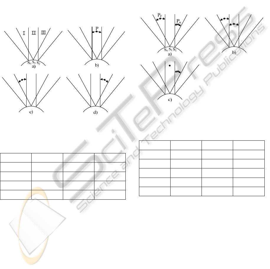
overlapped ultrasonic sensor ring. Fig. 1 shows three
adjacent ultrasonic sensors, S
, S
, and S
, which
are placed at the left, the center, and the right,
respectively. Due to beam overlapping, the entire
sensing zone of the ultrasonic sensor S
can be
divided into three sensing subzones, denoted by ‘I’,
‘II’, and ‘III’. In Fig.1, an obstacle P is depicted by a
bold.
First, let us consider the detection of a single
obstacle using three overlapped ultrasonic sensors.
Let ρ
, ρ
, and ρ
be the distances of the obstacle P
measured by three ultrasonic sensors, S
, S
, and
S
, respectively. Table 1 shows the distance
measurements of S
, S
, and S
, depending on to
the position of P among one of three sensing
340
Kim S., Jang J. and Kim H. (2010).
MOBILE ROBOT OBSTACLE DETECTION USING AN OVERLAPPED ULTRASONIC SENSOR RING.
In Proceedings of the 7th International Conference on Informatics in Control, Automation and Robotics, pages 340-343
DOI: 10.5220/0002878803400343
Copyright
c
SciTePress
subzones, either I, II, or III. In Table 1, ′∞′ indicates
the situation that P cannot be detected by the
corresponding ultrasonic sensor. Seen from Table 1,
the combination of three ultrasonic sensors which
return finite measured distances varies according to
where the obstacle belongs among three sensing
subzones. This implies that the sensing subzone to
which the obstacle belongs can be determined based
on the combination of three ultrasonic sensors
returning finite measured distances. It should be
noted that the beam overlapping between adjacent
ultrasonic sensors can lead to the significant
reduction in positional uncertainty.
Figure 1: Single obstacle detection using overlapped
ultrasonic sensors.
Table 1: Distance measurements of ultrasonic sensors in
the case of single obstacle detection.
2b) 2c) 2d)
P
II I III
S
∞
ρ
∞
S
ρ
ρ
ρ
S
∞ ∞
ρ
Next, let us consider the detection of double
obstacles using three overlapped ultrasonic sensors.
Note that the number of obstacles that can be
detected by two adjacent ultrasonic sensors is at
most two, regardless of how many obstacles are
present in front of them. Assume that one obstacle is
present at far distance, called the far obstacle and
denoted by P
, and the other obstacle is present at the
near distance, called the near obstacle and denoted
by P
. Fig. 2 shows three different cases of how the
far and near obstacles are located. Let ρ
,
and
ρ
,
ρ
,
, , 1,2, be the distances of the
obstacles, P
and P
, measured by three ultrasonic
sensors, S
, S
, and S
, respectively.
Table 2 shows the distance measurements of
three ultrasonic sensors, S
, S
, and S
, depending
on the relative positions of the far and the near
obstacles, P
and P
. Referring to Table 2, the
following decisions can be made on where P
and P
are positioned among three sensing subzones, I, II,
and III. For instance, if the left ultrasonic sensor
S
returns larger value than the other two ultrasonic
sensors, S
and S
, as shown in Fig. 2a), P
is
positioned within I and P
is positioned within III.
Figure 2: Double obstacle detection using overlapped
ultrasonic sensors.
Table 2: Distance measurements of ultrasonic sensors in
the case of double obstacle detection.
3a) 3b) 3c)
P
I I II
P
III II III
S
ρ
,
ρ
,
∞
S
ρ
,
ρ
,
ρ
,
S
ρ
,
∞
ρ
,
3 MOBILE ROBOT
REFERENCED OBSTACLE
DETECTION
Each ultrasonic sensor of an ultrasonic sensor ring
returns the distance of an obstacle that is measured
with reference to the vertex of its own, called the
sensor referenced obstacle distance. On the other
hand, it is the obstacle position with reference to the
center of a mobile robot, called the mobile robot
referenced obstacle position that should be known
for the obstacle detection/avoidance of a navigating
MOBILE ROBOT OBSTACLE DETECTION USING AN OVERLAPPED ULTRASONIC SENSOR RING
341
mobile robot.
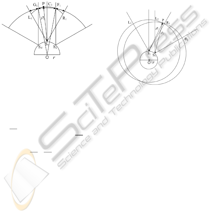
First, suppose that an obstacle P is present at the
distance ρ
within the unoverlapped sensing subzone
II of the ultrasonic sensor S
, as shown in Fig. 3. Let
G
and F
denote the intersecting points of the circle
of radius ρ
centered at the point S
, and the right
beam boundary of the ultrasonic sensor S
and the
right beam boundary of the ultrasonic sensor S
,
respectively.
Figure 3: The mobile robot referenced position of an
obstacle within the unoverlapped sensing zone.
Due to the positional uncertainty, an obstacle P
can exist at a certain point along the arc G
C
F
of
radius ρ
centered at the point S
, instead of the arc
L
C
R
. Considering that the ultimate goal of
obstacle detection is to prevent possible collision
with obstacles, it is reasonable to take conservative
stance in guessing the obstacle position. To prepare
for the worst case scenario, the collision free region
can be specified as the intersection of the circle of
radius OF
centered at the point O and the cone of
angle G
OF
centered along the line OC
. As a
result of the beam overlapping of an ultrasonic
sensor ring, 1) the radius of the collision free region
increases, that is, OF
OR
, and 2) the angle of the
collision free region decreases, that is, G
OF
L
OR
. The increased radius can allow a mobile
robot more room for obstacle avoidance, and the
decreased angle can improve the spatial resolution in
obstacle detection.
Next, suppose that an obstacle P is present at the
distance ρ
within the overlapped sensing subzone
III of the ultrasonic sensor S
, as shown in Fig. 7.
Let ρ
and ρ
be the distance of P from the vertices
of ultrasonic sensors, S
and S
, respectively. Owing
to the positional uncertainty of two ultrasonic
sensors, P exists along the arc L
R
of radius ρ
centered at the point S
, and it also exists along the
arc L
R
of radius ρ
centered at the point S
. As
shown in Fig. 4, the position of P can now be
obtained from the intersection of these two circles,
which results in two intersecting points in general.
Finally, the obstacle position can be uniquely
determined out of two intersecting points, based on
the relative locations of ultrasonic sensors, S
and
S
. It should be noted that the problem of
uncertainty does not exist anymore for an obstacle
within the overlapped sensing subzone, although the
measurement errors may still affect the accuracy in
computing the obstacle position.
Figure 4: The mobile robot referenced position of an
obstacle within the overlapped sensing subzone.
4 EXPERIMENTAL RESULTS
An omnidirectional overlapped ultrasonic sensor
ring prototype was built using the ultrasonic sensor
modules which contain MA40B8 of beam width
α 50° from Murata Inc. As shown in Fig. 5,
twelve ultrasonic sensor modules are first installed at
a regular spacing of β30° between two circular
acrylic plates of radius 19cm, which is then
fixed on top of a circular mobile robot
concentrically.
First, a mobile robot is commanded to move
along a straight line, which is 1 m apart from a
circular obstacle of diameter 12.5 cm. Fig. 6 shows
the division of the straight line depending on the
combination of ultrasonic sensors involved in
obstacle detection. It can be observed that the
distance from P
to P
is about 170 cm and the
distance from P
to P
is about 140 cm. Using these
data, the effective beam widths can be calculated:
70° for the center ultrasonic sensor and 60° for the
left and right ultrasonic sensors.
ICINCO 2010 - 7th International Conference on Informatics in Control, Automation and Robotics
342
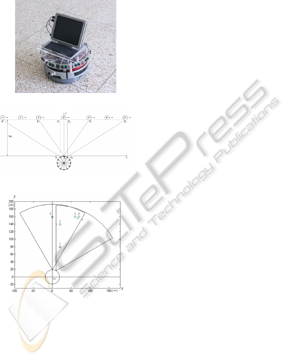
Figure 5: Our overlapped ultrasonic sensor ring prototype.
Figure 6: The experimental results for single obstacle
detection.
Figure 7: The experimental setting and results for
computing mobile robot referenced obstacle positions.
Next, for five different locations of an obstacle,
we compute the mobile robot referenced position of
an obstacle from the measured distances of three
ultrasonic sensors. Fig. 7 shows the actual and the
computed obstacle positions, which are marked by
'o' and 'x', respectively. The discrepancy between the
actual and the computed obstacle positions tends to
increase as an obstacle is located away from the
center of the overlapped ultrasonic sensor ring and
close to the boundary of the overlapped sensing
subzone. However, it is confirmed through repetitive
experiments that the maximum discrepancy is
bounded within 10 cm.
5 CONCLUSIONS
In this paper, we proposed an overlapped ultrasonic
sensor ring which consists of relatively small
number of low cost ultrasonic sensors with low
directivity, to reduce the positional uncertainty in
obstacle detection. The proposed ultrasonic sensor
ring made of low directivity ultrasonic sensors is
advantageous over its high directivity counterpart in
both sensor device and data processing requirements.
It is expected that the results of this paper can
facilitate early deployment of low cost mobile
platforms for personal service robots.
REFERENCES
Borenstein, J. and Koren, J., 1989. Real-Time Obstacle
Avoidance for Fast Mobile Robots. In IEEE Trans.
Sysems, Man, and Cybernetics, vol. 19, no. 5, pp.
1179-1187.
Choset, H., Nagatani, K., and Lazar, N. A., 2003. The
Arc-Traversal Median Algorithm: A Geometric
Approach to Increase Ultrasonic Sensor Azimuth
Accuracy. In IEEE Trans. Robotics and Automation,
vol. 19, no. 3, pp. 513-522.
Crowley, J. L., 1989. World Modeling and Position
Estimation for a Mobile Robot Using Ultrasonic
Ranging. In Proc. IEEE Int. Conf. Robotics and
Automation, pp. 674-680.
Elfes, A., 1987. Sonar-Based Real-World Mapping and
Navigation. In IEEE J. Robotics and Automation, vol.
RA-3, no. 3, pp. 249-265.
McKerrow, P. J., 1993. Echolocation-from Range to
Ontline Segments. In Robotics and Autonomous
Systems, vol. 11, no. 4, pp. 205-211.
Moravec, H., and Elfes, A., 1985. High Resolution Maps
for Wide Angles Sonar. In Proc. IEEE Int. Conf.
Robotics and Automation, pp. 116-121.
Murphy, R., 2000. Introduction to AI Robotics, The MIT
Press.
Thrun, S., Burgard, W., and Fox, D., 2005. Probabilistic
Robotics, The MIT Press.
Wijk, O. and Christensen, H. I., 2000. Triangulation-
Based Fusion of Sonar Data with Application in Robot
Pose Tracking. In IEEE Trans. Robotics and
Automation, vol. 16, no. 6, pp. 740-752.
MOBILE ROBOT OBSTACLE DETECTION USING AN OVERLAPPED ULTRASONIC SENSOR RING
343
