
AUTOMATIC CALIBRATION OF A MOTION CAPTURE SYSTEM
BASED ON INERTIAL SENSORS FOR TELE-MANIPULATION
J
¨
org Hoffmann
Institut f
¨
ur Informatik II, University of Bonn, Germany
Bernd Br
¨
uggemann
Fraunhofer Institute for Communication, Information Processing and Ergonomics (FKIE), Wachtberg, Germany
Bj
¨
orn Kr
¨
uger
Institut f
¨
ur Informatik II, University of Bonn, Germany
Keywords:
Telerobotics and teleoperation, Motion capturing, Automatic calibration, Inertial sensors.
Abstract:
We introduce an intuitive way of controlling a manipulator. This control should fulfill several constraints like
low room consuming and operable in a short time. With this constraints in mind we chose an inertial sensor
based motion capturing system. Such systems have to be adapted to the user. We present a method to adapt
the system by a fast calibration while it is been used. The calibration does not require specified given motions.
The soundness of the system is shown in synthetic and real experiments.
1 INTRODUCTION
Interactive manipulation of their environment is an es-
sential task for robots. To provide a good tool for ma-
nipulation in most cases robots are equipped with a
robot arm. Controlling such a manipulator is a chal-
lenging task, especially if it should be remotely con-
trolled. The operator usually has an impression about
the environment by video only. Based on this few in-
formation he has to perform complex motions with
a manipulator. Controlling each joint separately de-
mands long previous training and high concentration.
The operator has to plan a sequence of motions for
each joint in advance. The difficulty of these opera-
tions is raised by the fact that it may be necessary to
re-adjust the joints during the motions.
As part of danger defence and disaster response
exploring a potential dangerous area without exposing
persons becomes more and more important. On one
hand, threats by terrorist groups can cause great dam-
age with relatively small effort. On the other hand,
disasters in industrial areas may release dangerous
and not easily detectable chemicals (TICs). If such an
emergency occurs, information about what has hap-
pened and how the situation is developing is crucial
for an effective response. Here robots can help to ac-
quire desired information without exposing personnel
to unknown risks. Such robots can be equipped with
several sensors to identify different threats. But often
it is just as important to manipulate the environment.
This may occur e.g. if a suitcase has to be opened, or
a sample has to be taken for analysis.
Nowadays most robots, which are meant to be
used within a disaster area are at least partly remote
controlled. So the operator has no direct line of sight
to the robot and the area the robot is working in. Be-
ing reliant on only few sensors (like a camera) com-
plex manipulations have to be executed. Often such
tasks are time critical and far away from any available
infrastructure. Therefore the needed control method
for the robot arm has to fulfill several constraints: In-
tuitively usable, can be employed quickly, space sav-
ing and easy to transport, and pose only small restric-
tions to the mobility of the user
In this paper we present a method to steer the ma-
nipulator directly by the operator’s movements with-
out the need of an exoskeleton. We use five iner-
tial sensors to capture the motions of the operator.
The most important part in our system is the auto-
calibration which makes an exact sensor placement
121
Hoffmann J., Brüggemann B. and Krüger B. (2010).
AUTOMATIC CALIBRATION OF A MOTION CAPTURE SYSTEM BASED ON INERTIAL SENSORS FOR TELE-MANIPULATION.
In Proceedings of the 7th International Conference on Informatics in Control, Automation and Robotics, pages 121-128
DOI: 10.5220/0002880301210128
Copyright
c
SciTePress

unnecessary. In fact we only need to know roughly
where the sensors are positioned.
The remainder of the paper is organized as fol-
lows: In section 2 related works are presented and dif-
ferent ways of remotely controlled manipulators are
shown. In section 3 the problem and its constraints
are described while section 4 shows the preprocess-
ing of the sensor signals. The automatic calibration
for our inertial sensor based motion capturing system
is presented in section 5, followed by the robot arm
control mechanism in section 6. Section 7 presents
results of the calibration as well as its effect on the di-
rect manipulation controls. The paper closes with our
conclusions.
2 RELATED WORK
2.1 Robot Arm Control
Industrial robots are the prime example of the mar-
ket’s demand of manipulators. But also in mobile
robotics the control of manipulators is essential. Here,
in contrast to the industrial robots, the movement is
not predefined and has to be adapted to the situation
and the task. So, in the course of time several dif-
ferent methods for controlling a manipulator were de-
veloped. Roughly those methods can be divided into
remotely controlled and autonomous movements.
Remotely controlled drives have the advantages
to fall back on the decision of the operator. Al-
though there is no need of autonomous decisions the
system has to provide the operator with full control
and information needed for the motion task. Within
the remotely controlled manipulators, methods can be
distinguished by their input devices, e.g. joysticks
(some mentioned in (Laycock and Day, 2003)). From
standard joysticks to those with force feedback, the
boundaries to master-slave control mechanisms are
fluid.
The idea to couple a control mechanism directly
to the manipulator is rather old (e.g. (Goertz, 1954)).
Such master-slave approaches have some advantages
like being very accurate and the operator is always
aware of the motions the manipulator will perform.
Additionally, master-slave controls are able to pro-
vide the operator with haptic feedback. So there can
be more resistance within the master device if the ma-
nipulator will be near to an obstacle or it is possible
to feel the structure of a surface (e.g. (Tachi et al.,
1990; Yokokohji and Yoshikawa, 1992)).
In-between master-slave devices and joysticks,
there are exoskeletons. Such devices are worn by the
operator. Exoskeletons are available for just a limb
(e.g. an arm) or as whole body device (Bergamasco
et al., 1994). Its advantages are a very precise recon-
struction of the human motion and, compared to the
master-slave approach, less space is needed. But due
to the stiff construction, those exoskeletons prevent
the operator from performing movements in a natural
way.
Motion capturing is another approach to control
a manipulator by reconstructing human movements.
(e.g. (Miller et al., 2004; Pollard et al., 2002)). Ap-
proaches range from camera based motion capturing
(with active or passive markers) to motion capturing
with inertial sensors.
2.2 Motion Capturing with Inertial
Sensors
Many techniques for capturing human motions have
been developed in the last decades. Most of these
techniques suffer from several disadvantages: they are
not portable, need complex calibrations, or have dis-
turbing exoskeletons. A good overview over the most
important techniques is given in (Welch and Foxlin,
2002).
In the last years inertial sensor systems have be-
come more popular for many applications. They are
used for action recognition in games (Slyper and Hod-
gins, 2008), and for detection of typical or similar pat-
terns in medical applications (Sabatini et al., 2005;
Chang, 2006). A lot of work has been done on par-
tial motion capturing, where only special parts of the
body, as upper limbs for example, are considered. In
this area applications like home rehabilitation sys-
tems (Zhou et al., 2006; Zhou and Hu, 2007; Tao
et al., 2007) or robot controllers (Miller et al., 2004)
have been developed. For tracking applications sev-
eral systems based on fusion of inertial sensors and a
variety of other systems have been introduced (Foxlin,
2005). For full body motion capturing a portabel
system based on inertial sensors combined with an
acoustic system was designed (Vlasic et al., 2007).
Since Nintendo introduced the Wiimote in 2006 a lot
of applications were developed (Schou and Gardner,
2007; Lee, 2008; Shiratori and Hodgins, 2008), while
low cost sensors are available for mass market appli-
cations.
All these applications have to face similar techni-
cal difficulties. The data of inertial sensors are noisy
and may contain a drifting. This problem is tack-
led using some basic techniques in all applications.
Kalman filters are widely used for an optimal estima-
tion based on data of multiple sensors (Vlasic et al.,
2007; Zhou and Hu, 2007; Tao et al., 2007; Shira-
tori and Hodgins, 2008), especially when different
ICINCO 2010 - 7th International Conference on Informatics in Control, Automation and Robotics
122

Figure 1: Positioning of the five inertial sensors on the right
arm. Each joint is assigned to one sensor. The sensor on the
shoulder is used as fix point.
types of sensors are combined. A Monte Carlo op-
timization can be used as basis for the estimation of
positions and orientations (Zhou et al., 2006). For
recognition of typical patterns in acceleration data
classical signal processing techniques, like phase de-
tection (Sabatini et al., 2005) or frequence analysis
by Haar wavelet transformations (Slyper and Hod-
gins, 2008) have been employed. To estimate the di-
rection of gravity several heuristics have been devel-
oped (Miller et al., 2004; Foxlin, 2005).
3 PROBLEM DESCRIPTION
To directly control the robot manipulator, the move-
ment of the whole human arm has to be reconstructed.
Therefore, we used four inertial sensors. One for each
part of the arm: Upper arm, lower arm, hand, and fin-
gers. A fifth sensor is needed to be positioned on the
shoulder as a fix point (see Figure 1). The sensors pro-
vide their orientation but no information about their
position in space. If the setup of the human arm and
each sensor positioning on that arm is known, then it
is possible to compute the arm configuration:
Let G
i
be the missing position for the i-th joint, q
i
the orientation measured by sensor i and s
i
the length
of the segment i (from joint i to i + 1). R
q
i
(v) is the
rotation of vector v around q
i
. Then the desired posi-
tions of each joint are:
G
0
= [0,0,0]
T
(1)
G
i
= G
i−1
+ R
q
i
([s
i
,0,0]
T
) (2)
Those equations needs the sensors to be oriented
in direction of the bone it is connected to. Unfortu-
nately the positioning of the sensors in reality is not
as accurate as it is needed. So each sensor has a bias
to the desired positioning. Figure 2 shows such a sit-
uation. Assuming the positioning is accurate, the ori-
entations of the sensors imply a bended arm. When
taken the faulty positioning α and β into account it can
be recognized that the original arm configuration cor-
responds to a stretched arm. If the sensors are placed
without calibration with calibration
Figure 2: Imprecise positioning of sensors will cause false
reconstruction of movements. Assuming the sensors are
placed carefully the orientation implies a bended arm (left).
When knowing that the sensors are placed faulty by an angle
α and β the arm has to be reconstructed as streched (right).
carefully on the human arm, the result will be alright
but not very precise. But for a trustworthy and accu-
rate result it is important to know the difference be-
tween the bone orientation and its corresponding sen-
sor.
When the system is calibrated, the reconstructed
motions of the operator can be used to control the ma-
nipulator. As the used manipulator (and many robot
arms currently available) has not the same morpholo-
gies as the human arm, it is not possible to map the
reconstructed joint angles directly to the robot. So
another mapping has to be found. We used a simple
mapping by directly using the position and orienta-
tion of the operator’s fingers. These informations are
easy to compute with the calibrated arm model. As
the finger’s position is related to the shoulder, it can
be used to provide a target for the manipulator’s tool
center point (TCP). This means that there will be no
direct correlation between the pose of the human arm
and the manipulator but a correlation between the po-
sition of the fingers and the TCP.
4 SIGNAL PREPROCESSING
We use two different types of sensor data provided
by the inertial sensor system. First, we get orientation
data which are used to perform forward kinematics on
our arm model. Second, we obtain acceleration data
which are used for the calibration. While the orienta-
tion data is reliable over long time periods the accel-
eration data is more noisy and is afflicted by drifting.
In this section we show how we proceed with these
artifacts in our sensor data.
4.1 Removing Noise
We have to remove noise on both sensor signals: The
orientation data and the acceleration data. Both data
types have a high frequency noise. To reduce this
noise, we used a standard binomial low pass filter. As
the velocity signal is a function in the position space,
a filter with a window w = 20 data points is chosen.
AUTOMATIC CALIBRATION OF A MOTION CAPTURE SYSTEM BASED ON INERTIAL SENSORS FOR
TELE-MANIPULATION
123

0 100 200 300 400 500 600 700 800
−1
0
1
2
x [m/s]
0 100 200 300 400 500 600 700 800
−1
0
1
2
y [m/s]
0 100 200 300 400 500 600 700 800
−1
0
1
2
z [m/s]
Figure 3: Velocity data for the three axis. Without zero
velocity updates the data show a clear drift (red), with zero
velocity updates the drift is visibly reduced (blue).
Since the orientations are represented by quaternions,
we employ a smoothing filter to the orientation data
like it is described by (Lee and Shin, 2002) in order
to achieve reliable data.
4.2 Removing Drifting
The acceleration measurements include the gravita-
tion. These so-called local accelerations have to be
converted to global acceleration, i.e. accelerations
without gravitation. When using the sensor orienta-
tion to remove acceleration caused by gravity, small
errors in the orientation accumulate to large drifts in
the rotational acceleration.
We can efficiently remove drifting by apply-
ing zero velocity updates (ZUPT) introduced by
(Grejner-Brzezinska et al., 2001). Regardless whether
we know the exact positions and orientations of our
sensors: If the orientations do not change neither will
the positions. We computed the velocity of each joint
of our arm model. If these velocities are slower than a
threshold (we use 0.05
m
s
) we presume that the arm
is not moving, i.e. its accelerations are zero. The
measured non zero accelerations at these zero veloc-
ity points describe how the data have drifted. We use
these information to correct the acceleration between
two zero velocity points by changing the accelerations
linearly. Some results of this method are given in Fig-
ure 3. Without zero velocity updates the data show a
clear drift away from the zero line, with zero velocity
updates the drift is visibly reduced. It shows that the
sensor drifting can be removed clearly. Note that this
technique is an offline strategy. However, this is no
drawback, since we need the acceleration data only
for the calibration of the sensors. For reconstruction
we only use the orientation data, which do not have
any drifting at all.
5 SENSOR CALIBRATION
The goal of our calibration is to detect the sensors’
positions and orientations on the operator’s arm auto-
matically. Figure 2 shows the importance of this step,
since a wrong bias may lead to faulty reconstructions
of the arm motions. During our calibration step we
use a model of the human arm. This model consists
of four by spherical joints connected segments corre-
sponding to: Upper arm, lower arm, hand, and fin-
gers. We assume that the first joint of the model con-
nects the upper arm to a world coordinate frame. This
model contains also simulated sensors on each seg-
ment. Based on the models movement simulated data
can be acquired. The calibration goes on as follows:
1. Recording of calibration motion
2. Signal preprocessing (see section 4)
3. Apply measured orientations to the model (move
the model)
4. Derive simulated data from model
5. Compare simulated data with measured data
6. Change parameters of the arm model to minimize
the error. Continue with step 3.
Step 3 to 6 are repeated until the resulting error is
small enough. So the calibration can be expressed as a
optimization problem, where the distance between the
measured data and the data derived from the model is
minimized:
min
~
t,~q,
~
s
D
D
sensors
,D
model
(O
sensors
,
~
t,~q,
~
s)
, (3)
where:
• D is some distance function
• D
sensors
are data computed from the measured ac-
celerations of the sensors
• D
model
are data computed with the arm model
which depends on:
– O
sensors
are measured orientation data
–
~
t position of each sensor on its corresponding
segment
– ~q orientation of each sensor with respect to its
corresponding segment
–
~
s length of each segment
5.1 Optimization Problem
The optimization crucially depends on two different
parameters. First the distance function D. This func-
tion defines the similarity of two data sets D. As we
ICINCO 2010 - 7th International Conference on Informatics in Control, Automation and Robotics
124

have to compare data of different quality (i.e. posi-
tion, orientation and length) different distance func-
tions have to be considered. The actually used func-
tion D may consist of one or any combination of dif-
ferent distance functions. The adequate combination
for our problem will be determined in the results. The
three chosen basic distance functions are:
D
E
=
q
(D
sensors
− D
model
)
2
(4)
D
cos
= arccos
D
sensors
kD
sensors
k
,
D
model
kD
model
k
(5)
D
dir
=
|
|D
sensor
− D
model
|
| (6)
The second important parameter of the optimiza-
tion problem is the kind of data D we use. For the
optimization we only use measured acceleration data
and quantities deduced from the acceleration. Hence
the usable features are:
• aG: local acceleration (measured data from sen-
sors)
• a: global acceleration (without gravitation)
• v: velocity
• p: position
Although all the deduced features are computed from
the local acceleration, there is a difference in qual-
ity. As mentioned above the global acceleration is
computed using the measured orientation. There-
fore, methods like zero velocity updates are applica-
ble. The velocity data v are obtained from integrating
a and are smoother which could result in a more stable
optimization. By additional integration we obtain po-
sition data p, which leads to a further generalization.
So D may be any combination of those features.
The goal is to get D
sensors
, the measured data, and
D
model
, the results from the model with respect to the
chosen distance function as similar as possible. The
movements of the model are produced by orienta-
tion data O
sensors
. The arm model is configured by
the segments length, position and the orientation of
each sensor. Depending on this configuration the for-
ward kinematics of the arm induced by O
sensors
results
in a specific movement. This movement generates the
data D
model
. This constitutes a non-linear optimization
problem which we solved by using the Levenberg-
Marquardt algorithm.
5.2 Calibration Motion
The result of the calibration step depends on the un-
derlying movement. There is no need for specific
given motion that has to be performed. However,
the calibration motion should cover movements in
Figure 4: The used manipulator. Originally it is mounted
on an EOD robot.
any degree of freedom, if possible. As the calibra-
tion movement is used to determine the arm param-
eters, a wide range of different motions will result
in a well defined solution. Also it is expected that
the optimization process will converge faster. In gen-
eral to provide better results the calibration motion
should include fast movements, pauses (for zero ve-
locity updates) and movements in any possible direc-
tion. Note that the main part of the movements should
be faster than the ZUPT threshold, otherwise the cali-
bration might be unreliable. Experiments show that
calibration movements of less than one minute are
sufficient.
6 ROBOT ARM CONTROL
The manipulator used in our experiments is the robot
arm normally mounted on the teleMAX robot of the
manufacturer Telerob. The configuration is similar
to a human arm, with two differences. First, it is
equipped with a telescope joint. Second and more im-
portant, it is rotated by 90 degrees so that the shoulder
does not turn vertically but horizontally (see Figure
4). The robot arm is equipped with a so called TCP
control. With its help the tip of the gripper can be
moved along and rotate around all axis. Every move-
ment command is related to the point of origin in the
shoulder joint. Using the inertial sensor based recon-
struction of the human arm, the finger position can
be determined and send to the manipulator. The goal
of the presented control system is to give the opera-
tor a feeling for the movements of the manipulator.
Therefore, the relation of human actions and robot re-
actions must be visible to the operator. If a movement
is performed by the operator the manipulator has to
react and imitate this movement. When designing the
controler, one has to be kept in mind that the used ma-
nipulator is not able to perform movements as fast as
humans.
AUTOMATIC CALIBRATION OF A MOTION CAPTURE SYSTEM BASED ON INERTIAL SENSORS FOR
TELE-MANIPULATION
125

To let the manipulator perform a similar trajec-
tory as the operator, a list of end effector positions
could be implemented. While the human performs
the movement such a list is filled and the manipulator
will move to the given end effector positions as fast
as possible. We decided not to use such a technique
because of the speed gap between operator and ma-
nipulator. Experiments showed that in our setup there
is no feeling of being directly coupled to the manipu-
lator. The manipulator will be more and more behind
the operator’s movements. Therefore, we decided to
implement a direct transmission of the current opera-
tor’s arm position. This provides the operator with a
feeling of being directly connected to the manipulator
and, in contrast to the list, it is possible to interrupt a
not desired movement. But to define a trajectory the
TCP has to follow, the operator has to move in the
same speed as the robot does. Otherwise only target
points are given, which the robot tries to reach on a
linear way.
Fully stretched the manipulator has a range of
about 1.50 m, more than a human arm. To achieve the
full length of the manipulator, there must be a scaling
function between the human motion and the manipu-
lator movement. In experiments with different users,
seemed to scaling the up-down direction (the z-axis)
provided an unnatural feeling. Scaling in x- and y-
axis seemed to be no problem to adapt to. So a scal-
ing for x- and y-axis is used to allow the operator to
use the whole operation range of the manipulator. We
decided not to use any scaling for the z-axis.
7 RESULTS
7.1 Calibration of Synthetic Examples
To test the calibration and the used optimizer, we first
used synthetic data. The synthetic data were produced
by the arm model. Here for, the model is moved
and the simulated sensors provide us with accelera-
tion and orientation data. As stated in Section 5 the
calibration mechanism has to find the correct posi-
tioning of each of the four sensors and the length of
the segment corresponding.
To check whether the optimizer can find the cor-
rect configuration we performed several experiments.
On the one hand, we tested situations where only one
of the parameters is erroneous. On the other hand we
have configurations where all three parameters were
unknown. For example we tested the calibration of
the system with sensors erroneous in orientation. So
the model was build up with the sensors in orientation
not equal to the segment’s orientation. Movements
Figure 5: Some example results for calibration of synthetic
data with all three parameters faulty. E(tr) is the error of the
positioning of the sensors, E(ori) the error of the orientation,
E(len) the error of the segment length.
were simulated and the sensor data computed. These
sensor data were now used by the optimizer. It knows
where the sensors are and how long each segment is.
It does not know in which orientation the sensors are
mounted. The experiment shows that the optimizer
was able to determine the sensors’ orientations. The
described experiment was repeated with each parame-
ter being erroneous and also with all three parameters
erroneous.
As the optimizer itself is also parameterized, the
output depends on the chosen combination of distance
functions and the features chosen (see Section 5). To
check which combination of distance functions and
features is adequate to solve the problem, we tested
every possible combination on the synthetic data. In
figure 5 some results are given for the experiments
with all three parameters erroneous.
There are some combinations which are not suit-
able to use but it shows that there are several differ-
ent combinations of metrics and features which en-
able the optimizer to find the original arm configura-
tion. This shows that the method is able to find the
correct configuration in general. The next step is to
see whether the system is also stable with real data.
7.2 Calibration of Real Sensor Data
To test how the calibration step is effective to the mo-
tion reconstruction on real data a ground truth is nec-
essary. We used an optical motion capturing system
to compare the real movement of the operator with
the uncalibrated and calibrated reconstruction from
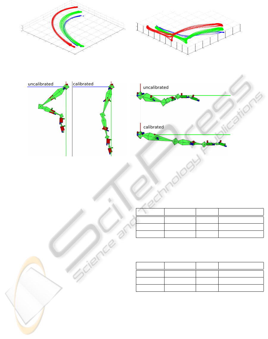
our system. In Figure 6 two example movements are
shown. The red crosses show the finger positions
(used as target position for the TCP of the manipu-
lator) of the uncalibrated system. The green circles
show the calibrated reconstruction. The blue dots rep-
resent the data from the optical system. In the left
picture a wiping motion is shown. The right digram
shows a gripping motion. In both examples the cali-
brated system performs more precise with respect to
the ground truth.
To show the effect of calibration to the motion re-
construction we used a poorly positioned system to
reconstruct a stretched arm. In Figure 7 the wrong
ICINCO 2010 - 7th International Conference on Informatics in Control, Automation and Robotics
126
−1
−0.8
−0.6
−0.4
−0.2
0
0.2
0.4
0
0.1
0.2
0.3
0.4
0.5
0.6
0.7
0.8
0.9
−0.2
0
0.2
−1
−0.8
−0.6
−0.4
−0.2
0
0.2
0.40
0.1
0.2
0.3
0.4
0.5
0.6
0.7
0.8
0.9
−0.5
0
0.5
Figure 6: Comparison between an optical MoCap system as ground truth and our inertial sensor based system. The red
crosses: finger positions of the uncalibrated system, green circles: calibrated reconstruction, blue dots: optical system.
Figure 7: Arm model before and after calibration. The underlying pose is a stretched arm. As the sensors on upper and lower
arm were not well orientated, the uncalibrated model returns a bended arm. After calibration the model shows are pose much
more alike the operator’s actual arm configuration., a stretched arm. Left picture shows view from above, right picture from
the side.
reconstruction can be seen. This flexed position hap-
pens due to the fact that the model expects the sensors
to be aligned to the orientations of the segments. Af-
ter the calibration step the model is very close to the
real pose, but with a small error in the bended elbow.
7.3 Control
To show that the presented method in general is ade-
quate to control the manipulator we had different per-
sons to perform several tasks. Those tasks were:
• Perform an infinity symbol
• Push a small log from the corner of a table
• Grip the log, (whereas the opening of the gripper
is only slightly wider than the logs diameter)
Half of the users had never used this control method
before. They had to perform each of the tasks twice.
Once without any training, and once after some train-
ing. The results can be seen in Table 1 and 2.
Here you can see that, even totally untrained, most
users were able to use the manipulator in the desired
way. In fact the untrained test persons have a lower
failure rate as the trained people. This may result from
the ambitions of the trained people to be faster. This
seems to make them more careless.
Table 1: Performance of untrained users with the control
system.
task successful failure average time [s]
infinity 8 0 37
Pushing 8 0 49
Gripping 7 1 52
Table 2: Performance of fairly trained users with the control
system.
task successful failure average time [s]
infinity 14 0 34
Pushing 13 1 31
Gripping 12 2 35
Often expressed criticism was the gap between the
speed of the manipulator and the human arm. Most
users needed some time to adapt to the much slower
manipulator. So we expect better results when using
a more agile manipulator.
8 CONCLUSIONS
In this paper we presented a control method for a
robot arm. The main requirements to fulfill were an
AUTOMATIC CALIBRATION OF A MOTION CAPTURE SYSTEM BASED ON INERTIAL SENSORS FOR
TELE-MANIPULATION
127

intuitive control, simple usage, and little space con-
suming. Our system based on inertial sensors to be
worn on the operator’s arm. With the help of an au-
tomatic calibration function, the exact placement of
these sensors can be found, which makes an exact
placement obsolete. Hence, equipping the system is
rather simple and fast. The system is able to recon-
struct the motion of the operator and therefore, send
them to the manipulator. This results in a direct mo-
tion control where the user steers the TCP of the ma-
nipulator with his own movements. First experiments
showed that even untrained persons can use the con-
trol system to fulfill certain tasks.
However, the system showed some points to im-
prove, especially in its intuitive use. As it took a lot
of time to get used to the fact, that the operator only
steers the TCP but not the morphologies of the arm,
a next step in development will be to map the recon-
structed joint angles of the human arm to the joints of
the manipulator to achive a similar manipulator con-
figuration compared to the operator’s pose. Also a
continuous calibration could be useful. The calibra-
tion as it is designed showed no reason not to be used
parallel to the steering task. This enables the system
to react to changes e.g. a loose sensor or changes in
the magnetic field. Here experiments are necessary to
show if the system stays stable.
REFERENCES
Bergamasco, M., Allotta, B., Bosio, L., Ferretti, L., Parrini,
G., Prisco, G., Salsedo, F., and Sartini, G. (1994). An
arm exoskeleton system for teleoperation and virtual
environments applications. In Robotics and Automa-
tion, 1994. Proceedings., 1994 IEEE International
Conference on, pages 1449–1454 vol.2.
Chang, M. M. Y. (2006). Motion segmentation using in-
ertial sensors. In VRCIA ’06: Proceedings of the
2006 ACM international conference on Virtual reality
continuum and its applications, pages 395–399, Hong
Kong, China. ACM.
Foxlin, E. (2005). Pedestrian tracking with shoe-mounted
inertial sensors. IEEE Comput. Graph. Appl.,
25(6):38–46.
Goertz, R. (1954). Mechanical master-slave manipulator.
Nucleonics, 12(11):45–46.
Grejner-Brzezinska, D. A., Yi, Y., and Toth, C. K. (2001).
Bridging gps gaps in urban canyons: Benefits of zupt.
Navigation Journal, 48(4):217–225.
Laycock, S. and Day, A. (2003). Recent developments and
applications of haptic devices. Computer Graphics
Forum, 22(2):117–132(16).
Lee, J. and Shin, S. Y. (2002). General construction of time-
domain filters for orientation data. IEEE Transactions
on Visualizatiuon and Computer Graphics, 8(2):119–
128.
Lee, J. C. (2008). Hacking the Nintendo Wii Remote. IEEE
Pervasive Computing, 7(3):39–45.
Miller, N., Jenkins, O. C., Kallmann, M., and Matari
´
c, M. J.
(2004). Motion capture from inertial sensing for un-
tethered humanoid teleoperation. In Proceedings of
the IEEE-RAS International Conference on Humanoid
Robotics (Humanoids), Santa Monica, CA.
Pollard, N. S., Hodgins, J. K., Riley, M. J., and Atkeson,
C. G. (2002). Adapting human motion for the control
of a humanoid robot. In Proceedings of International
Conference on Robotics and Automation, pages 1390–
1397.
Sabatini, A., Martelloni, C., Scapellato, S., and Cavallo
(2005). Assessment of walking features from foot in-
ertial sensing. Biomedical Engineering, IEEE Trans-
actions on, 52(3):486–494.
Schou, T. and Gardner, H. J. (2007). A wii remote, a game
engine, five sensor bars and a virtual reality theatre.
In OZCHI ’07: Proceedings of the 19th Australasian
conference on Computer-Human Interaction, pages
231–234, New York, NY, USA. ACM.
Shiratori, T. and Hodgins, J. K. (2008). Accelerometer-
based user interfaces for the control of a physically
simulated character. In SIGGRAPH Asia ’08: ACM
SIGGRAPH Asia 2008 papers, pages 1–9, Singapore.
ACM.
Slyper, R. and Hodgins, J. K. (2008). Action capture
with accelerometers. In Proceedings of the 2008
ACM/Eurographics Symposium on Computer Anima-
tion.
Tachi, S., Arai, H., and Maeda, T. (1990). Tele-existence
master-slave system for remote manipulation. In Intel-
ligent Robots and Systems ’90. ’Towards a New Fron-
tier of Applications’, Proceedings. IROS ’90. IEEE In-
ternational Workshop on, pages 343–348 vol.1.
Tao, Y., Hu, H., and Zhou, H. (2007). Integration of vi-
sion and inertial sensors for 3D arm motion tracking
in home-based rehabilitation. The International Jour-
nal of Robotics Research, 26(6):607–624.
Vlasic, D., Adelsberger, R., Vannucci, G., Barnwell, J.,
Gross, M., Matusik, W., and Popovi
´
c, J. (2007). Prac-
tical motion capture in everyday surroundings. In SIG-
GRAPH ’07: ACM SIGGRAPH 2007 papers, page 35,
New York, NY, USA. ACM Press.
Welch, G. and Foxlin, E. (2002). Motion tracking: No sil-
ver bullet, but a respectable arsenal. IEEE Comput.
Graph. Appl., 22(6):24–38.
Yokokohji, Y. and Yoshikawa, T. (1992). Bilateral con-
trol of master-slave manipulators for ideal kinesthetic
coupling-formulation and experiment. In Robotics
and Automation, 1992. Proceedings., 1992 IEEE In-
ternational Conference on, pages 849–858 vol.1.
Zhou, H. and Hu, H. (2007). Upper limb motion estimation
from inertial measurements. International Journal of
Information Technology, 13(1).
Zhou, H., Hu, H., and Tao, Y. (2006). Inertial measure-
ments of upper limb motion. Medical and Biological
Engineering and Computing, 44(6):479–487.
ICINCO 2010 - 7th International Conference on Informatics in Control, Automation and Robotics
128
