
LEGS DETECTION USING A LASER RANGE FINDER FOR
HUMAN ROBOT INTERACTION
Fl
´
avio Garcia Pereira, Raquel Frizera Vassallo and Evandro Ottoni Teatini Salles
Department of Electrical Engineering, Federal University of Esp
´
ırito Santo
Av. Fernando Ferrari, 514, Goiabeiras, Vit
´
oria-ES, CEP 29075-910, Brazil
Keywords:
Human-robot interaction, Legs detection, Laser scanner.
Abstract:
The ability to detect humans is an important skill for service robots, especially if these robots are employed in
an environment where human presence is constant, for instance a service robot which works as a receptionist
in the hall of a hotel. The principal aim of the proposed method is to estimate the human position using data
provided by a Laser Range Finder (LRF). The method utilizes two Finite State Machines (FSMs) to detect
some leg patterns and, after that, it computes the probability of being a pair of legs for each detected pattern.
In order to validate the proposed method some experiments were performed and are shown.
1 INTRODUCTION
In recent years, great effort has been done in order
to improve Human-Robot Interaction (HRI) research
field. Researchers such as Bellotto and Hu (Bellotto
and Hu, 2009) claim that the studies of HRI are cur-
rently some of the most fascinating research field in
mobile robotics, and Bekey (Bekey, 2005) empha-
sizes the idea that cooperation and interaction among
men and robots are the big challenges of the next
years. Because that, the robots which will interact
with humans must have the skill to detect people. This
ability will enable robots to understand better and an-
ticipate human intentions and actions (Arras et al.,
2007). The main purpose of our work is to develop
a laser-based human detection in order to allow a mo-
bile robot to interact with people.
There are many researches concerning people de-
tection using laser scanners. The work done by (Car-
ballo et al., 2009) introduces a method for people de-
tection around a mobile robot using two layers of laser
scanners, thus two sets of features for each person
are detected. Based on these features and a previous
knowledge about human body shape, the human de-
tections is performed. In (Fod et al., 2002), the au-
thors present a technique to track moving objects in
a workspace covered by multiple lasers. The method
to detect people shown in (Arras et al., 2007), uses
a supervised learning technique to create a classifier
that facilitates such detection. The classifier is trained
using AdaBoost method. A way to detect line and cir-
cles from laser data in an indoor environment is in-
troduced by (Xavier et al., 2005). The authors still
perform leg detection by considering it as a circle
with some particularities like the diameter of the cir-
cle. The approach to track multiple moving objects
shown in (Schulz et al., 2001) uses laser data and
combines particle filters with existing approaches to
multi-target tracking. The system uses leg detection
and occupancy grids to detect people. Topp and Hen-
rik (Topp and Christensen, 2005) introduces the “Hu-
man Augmented Mapping” which represents an inte-
gration of automated map generation with learning of
environmental concepts. They propose a method sim-
ilar to the one presented in (Schulz et al., 2001) with
the difference that their method allows handling peo-
ple standing still, which is useful for interaction.
The authors of (Cui et al., 2005) present a system
that employs multiple laser scanner and one camera
to track multiple persons. They track people through
a meanshift method and laser tracking and fuse these
two information using a Bayesian formulation. The
work presented in (M
¨
uller et al., 2007) implements a
fusion of laser, sonar and vision data to find and track
people by a mobile shopping assistance robot. A sys-
tem to track people in real time in uncontrolled envi-
ronments is presented in (Scheutz et al., 2004). This
system combines leg detection based on laser data and
face detection implemented in the specialized hard-
ware cellular neural network (CNN) universal ma-
chine. Reference (Bellotto and Hu, 2009) presents a
multisensor data fusion techniques for tracking peo-
129
Garcia Pereira F., Frizera Vassallo R. and Ottoni Teatini Salles E. (2010).
LEGS DETECTION USING A LASER RANGE FINDER FOR HUMAN ROBOT INTERACTION.
In Proceedings of the 7th International Conference on Informatics in Control, Automation and Robotics, pages 129-134
DOI: 10.5220/0002880501290134
Copyright
c
SciTePress
ple by a mobile robot using a laser scanner and one
monocular camera. They extract the features from a
laser scanner and look for some leg patterns. Vision is
used for face detection and the human tracking is per-
formed by fusing the two different sensor data. Luo
et al. (Luo et al., 2007) describe a method to find and
track a human using a monocular camera, which is re-
sponsible for finding the human face, and a laser scan-
ner assembled on their robot, whose function is to find
human body and arms. The data sensor is fused by
statistical independence. In (Kleinehagenbrock et al.,
2002) a hybrid method for integrating laser range and
vision data is presented. They use the laser data to de-
tect human legs and colored images to find skin color
and face. These information are fused to better per-
form the human tracking.
The approach we present in this paper is focused
in detecting human legs using a laser scanner and to
determine their position. If the legs detection is posi-
tive, the robot starts interacting with the human. Our
method to detect legs is similar to the approach devel-
oped in (Bellotto and Hu, 2009). Their system finds
human legs after identifying some legs patterns that
correspond to legs apart, forward straddle and legs to-
gether. In our case, only two patterns are considered
legs apart and legs together. In order to find these
two patterns we implemented a Finite State Machine
(FSM) and for each pattern found we calculate the
probability of being a pair of legs. The advantages of
the proposed method are the low computational cost
(the implemented method performs each detection in
approximately 35ms), the simplicity (it only uses two
FSMs and a probability function to classify a pair of
legs) and the low quantity of parameters that need to
be estimated (the distance between the legs and the
difference between their widths).
The remaining of this paper is organized as fol-
lows. Section 2 presents the method to find human
legs using a laser scanner. Section 3 illustrates the
results of some performed experiments and, at last,
the conclusions and future work are presented in Sec-
tion 4.
2 LEGS DETECTION
The method to detect legs that we are going to present
extracts features from a laser scanner and, as the
method shown in (Bellotto and Hu, 2009), identifies
patterns relative to the legs posture. These patterns
correspond to the following situations: legs apart
(LA) and two legs together (LT). The structure of the
legs detection algorithm can be seen in Figure 1.
In order to determine the most common leg posi-
Laser Measures
X
Laser Measures
Variation
X
.
Z(X, X, R , d)
Pattern Generation
.
Detected Regions
Analysis
Finite State Machine
Legs Probability
P(E, L)
max
Figure 1: Structure of the proposed algorithm.
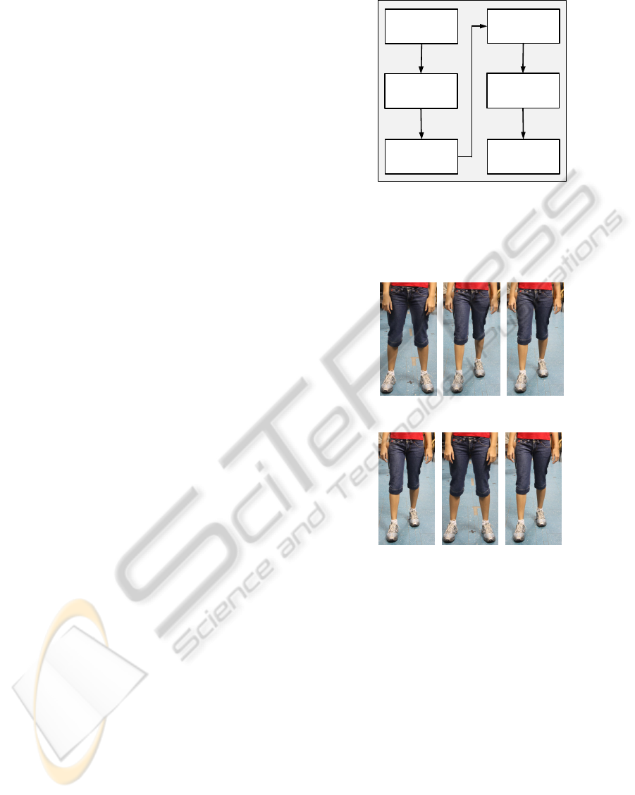
tion when a person stops and talks to another, some
people were observed. Figure 2 illustrates these situ-
ations.
(a) (b) (c)
(d) (e) (f)
Figure 2: Legs position. Legs apart (a)-(c). Legs together
(d)-(f).
2.1 Transitions Array
The distance measures provided by the laser scan-
ner are stored in an array X = [x
1
,x
2
,...,x
N
] where
x
i
is each distance measure captured and N is the
total number of readings. After that, an array with
the difference between two consecutive measures
(
˙
X = [ ˙x
1
, ˙x
2
,..., ˙x
N−1
]) is calculated as ˙x
i
= x
i+1
−
x
i
, with i = 1,2,...,N − 1. Then, the array Z =
[z
1
,z
2
,...,z
N−1
], which stores the transitions related
with each measure in x
i
, is built. Z is created based
on X ,
˙
X, R
max
and δ, where R
max
is the maximum
distance we are considering for the measures done by
the laser scanner (2m in this case) and δ is a distance
threshold. We define five different transitions:
• Transition 0: | ˙x
i
| < δ and x
i
= R
max
;
ICINCO 2010 - 7th International Conference on Informatics in Control, Automation and Robotics
130
• Transition 1: | ˙x
i
| > δ and ˙x
i
< 0;
• Transition 2: | ˙x
i
| < δ and x
i
6= R
max
;
• Transition 3: | ˙x
i
| > δ, ˙x
i
> 0 and x
i
6= R
max
;
• Transition 4: | ˙x
i
| > δ, ˙x
i
> 0 and x
i
= R
max
.
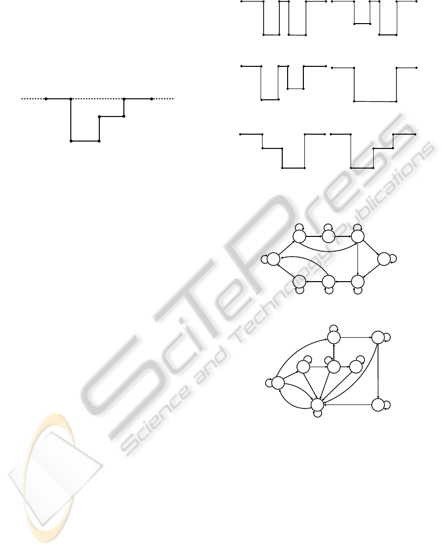
Figure 3 illustrates these five transitions. The
dashed line indicates the maximum measure, i. e.,
2m.
0 0
1
2
3
2
4
Figure 3: Defined transitions.
2.2 The Finite State Machines
After generating the array Z, it is performed a search
for leg candidates (LCs). These candidates are the re-
gions in Z that starts with a Transition 1 preceded by a
Transition 0 and finish with a Transition 4. Each can
be pre-classified either as single leg or as pair of legs
together candidate as follows. A LC is pre-classified
as a single leg if the distance between the extremities
is in the range (5cm,15cm). If this distance is big-
ger than 15cm and smaller than 32cm the LC is pre-
classified as a pair of legs together. Otherwise the LC
is discarded.
Once this pre-classification is accomplished, the
LCs are verified by two FSMs. One of them looks
for the LA pattern and the other for the LT. Each
state of these machines receives as input a value be-
tween 0 and 4, which represents the transitions al-
ready mentioned. A LA pattern is defined as a se-
quence 012401240 (Figure 4(a)-(c)), where the num-
bers represent the respective transitions. The LT pat-
tern can assume three different sequences: 0121240,
01240 and 0123240 (Figure 4(d)-(f)).
The patterns shown in Figure 4 correspond to the
legs position that appear in Figure 2.
Figures 5 (a) and (b) show, respectively, the FSMs
for detecting the LA and LT patterns. To simplify, the
inputs that take the FSMs to an invalid state are not
drawn in the schematics shown in those figures.
Notice that the numbers close to the arrows that
link the states are in the form input/output, where the
inputs are the values of the transitions in the vector
Z and the output can be either 0 (the pattern was not
identified) or 1 (recognized pattern).
2.3 Legs Probability
Once the detected patterns are classified by the FSMs,
some characteristics of the pair of legs are extracted
00
4
2
1
0
1
4
2
(a)
00
4
2
1
0
1
4
2
(b)
00
4
2
1
0
1
4
2
(c)
00
4
2
1
(d)
00
4
2
1
2
1
(e)
0 0
1
2
3
2
4
(f)
Figure 4: Leg patterns. Legs apart (a)-(c). Legs together
(d)-(f).
S0
S1 S2 S3
S4
S7 S6 S5
1/0
2/0
2/0
3/0
3/0
4/0
4/0
4/0
0/0
1/0
2/0
2/0
3/0
3/0
4/1
4/1
0/0
1/0
1/0
(a)
1/0
2/0
3/0
3/0
4/1
1/0
2/0
2/0
3/0
2/0
4/1
3/0
1/0
2/0
4/1
2/0
1/0
3/0
3/0
4/1
4/1
4/1
S0
S1
S2 S3
S4 S5
S7
S6
(b)
Figure 5: Finite State Machines. Legs apart (a) and legs
together (b).
in order to determine a probability of being legs, such
as the distance between the extremities (E) and the
difference between the width of each detected leg (L).
This probability was introduced to avoid situations
where, for example, there are two people near the
robot, one of them at the left extremity and the other
at the right extremity and, moreover, only one leg of
each one is detected. In this situation, the FSMs will
classify these legs as a pair of separate legs, but since
they are far from each other, they have low probabil-
ity of being a pair of legs which belongs to the same
person. Moreover, if a person stands still in front of
LEGS DETECTION USING A LASER RANGE FINDER FOR HUMAN ROBOT INTERACTION
131
the robot with legs apart and using a walking stick, it
could be interpreted as a leg. However, as the walk-
ing stick is thinner than a leg, it will not happen due
to the probability of being legs. This probability is
calculated as,
P(E,L) =
h
1 − tanh
(κL)
3
i
exp
−
(E −
¯
E)
2
2σ
2
,
(1)
where L is the difference between the width of each
leg, E is the distance of the exterior extremity of two
consecutive legs and κ is a positive constant. The av-
erage distance of human legs when they stop in front
of the laser and the standard deviation are given by
¯
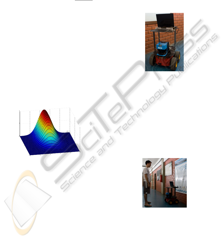
E and σ, respectively. Figure 6 shows the probabil-
ity of a pattern to be a pair of legs apart according to
variables E and L. For the situation where a pattern is
classified as a pair of apart legs by the FSMs, the pa-
rameters of Eq. 1 are
¯
E = 0.3037m, σ = 0.028m, oth-
erwise the values are
¯
E = 0.25m, σ = 0.0268m. The
adopted range for the variable E is [0.15m, 0.45m]
and for the variable L is [0, 0.1m]. The value of κ does
not change no matter the situation and it is κ = 15.
The graphic of being a pair of legs together is similar
to the legs apart and is not shown.
0
0.05
0.1
0.1
0.2
0.3
0.4
0.5
0.6
0
0.5
1
E [m]
L [m]
P(E, L)
Figure 6: Probability of being a pair of legs apart.
By observing the graphic presented in Figure 6, it
can be seen that the probability assumes its maximum
value when L is zero and E is equal to
¯
E.
3 EXPERIMENTAL RESULTS
The experiments were performed in an indoor en-
vironment using a mobile robot Pioneer 3-AT from
ActivMedia, equipped with a laser scanner Sick
LMS200. Even though the laser scanner provides dis-
tance measures from 0
◦
(right side of the robot) to
180
◦
(left side of the robot), the experiments were per-
formed using the measures from 60
◦
to 120
◦
, because
the aim is to detect people who are interested in in-
teracting with the robot. So, people who stop outside
the mentioned region, are not considered interested in
interacting.
The system was developed in C++ and runs in a
PC with MS Windows installed, a Core 2 Duo pro-
cessor 2.1GHz and 4GB RAM. This PC is capable
to execute around 25 loops per second, however we
fixed the execution time in 10 loops per second. The
robot used to perform experiments is shown in Fig-
ure 7.
Figure 7: Robot used to perform the experiments.
In order to show the reliability of the proposed
method, some experiments were performed. The
robot was positioned in a free area and, while the leg
detection algorithm was running, some people were
asked to stop in front of the robot in the same manner
they would stop when they want to talk to another per-
son and, sometimes, the experiment was performed
with more than one person. it were performed 152
detections and the algorithm was able to classify cor-
rectly 88.16% of the cases. Figure 8 shows a person
stopped in front of the robot and Figure 9 brings the
detection rates obtained during this experiment.
Figure 8: A person stopped in front of the robot.
Before showing the experimental results, it is
important to mention that during the tests nobody
stopped in front of the robot with the legs together.
Due to this, in order to perform a complete set of ex-
perimental results, some people were asked to stand
in front of the robot with their legs together. Follow-
ing subsections illustrate some experimental results of
the proposed leg detection algorithm.
ICINCO 2010 - 7th International Conference on Informatics in Control, Automation and Robotics
132
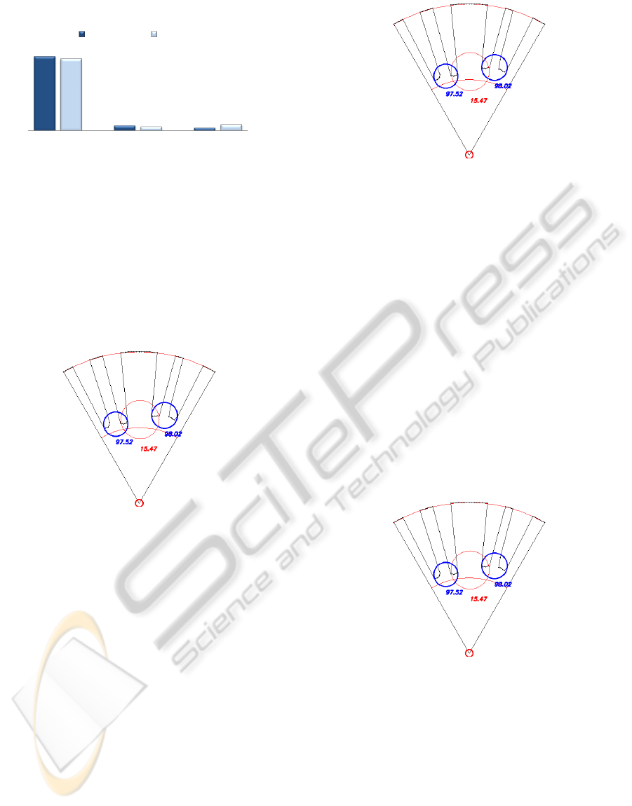
89,5%
6,6%
3,9%
86,8%
5,3%
7,9%
Hit Rate
False Positive
Not Detected
Legs Detection Rates
Legs Together
Legs Apart
Figure 9: Detection Rates.
3.1 Experiment 01
In this experiment two people were standing still in
front of the robot with the legs apart. Figure 10 shows
the distances measures captured by the laser scanner
and the obtained result for the leg detection algorithm.
The circles represent the detected pair of legs by the
FSMs, and the numbers represent the probability of
being legs of each detected pair of legs.
Figure 10: Experiment 01 - obtained results.
Notice that in Figure 10 there are three circles,
i. e., the FSMs detected three possible pair of legs
apart. However, the second pair of legs detected by
the FSMs has a low probability (15.47%) and it is not
considered a pair of legs. Moreover the other two
pairs have probabilities greater than 97% (see Fig-
ure 10) and are classified as a pair of legs. However,
if the people were closer one from another, the algo-
rithm would detect three pair of legs instead of two. It
can be solved with a face detection algorithm.
3.2 Experiment 02
In this experiment three people stood in front of the
robot and one set of measures was captured by the
laser. Two of them have the legs apart and the third
one has the legs together. The person who is in the
middle is the one with the legs together. Figure 11
shows the distance measures captured by the laser
scanner and the pattern identification done by the
FSMs represented by the circles.
Figure 11: Experiment 02 - obtained results.
The probabilities of being a pair of legs, calculated
after the legs pattern identification, are also shown in
Figure 11. Notice that all the patterns have a high
probability of being a pair of legs, which means that
the leg detection algorithm classified correctly the
people’s legs.
3.3 Experiment 03
As the Experiment 1, this experiment shows the legs
detection result for two people stopped in front of the
robot. However, here one person has the legs apart
and the other one has the legs together. This exper-
iment has the particularity that these two people did
not stop in front of the robot with the legs parallel. In
this case, as can be seen in Figure 12, one of the legs
is closer to the robot.
Figure 12: Experiment 03 - obtained results.
For this experiment, the pattern detection by the
FSMs and the probabilities of being a pair of legs are
shown in Figure 12. Although the legs are not par-
allel, the algorithm was able do classify correctly the
patterns detected by the FSMs.
LEGS DETECTION USING A LASER RANGE FINDER FOR HUMAN ROBOT INTERACTION
133

4 CONCLUSIONS AND FUTURE
WORK
We proposed in this paper a method to find human
legs using a LRF. The method utilizes the distance
measures provided by the laser scanner and look for
some legs patterns using two FSMs and, after that,
calculates the probability of each detected pattern be-
ing a pair of legs.
Some experiments were presented to show the
performance of the proposed method. It was demon-
strated that the method can detect human legs with
accuracy, but since we used only laser sensor infor-
mation, some false positives can be detected. In or-
der to reduce this false positives and solve occlusion
cases, our future work is concerned in introducing a
face detection and, thus, performing human-robot in-
teraction.
REFERENCES
Arras, K., Mozos, O., and Burgard, W. (2007). Using
boosted features for the detection of people in 2d
range data. In 2007 IEEE International Conference on
Robotics and Automation (ICRA 2007), pages 3402–
3407.
Bekey, G. A. (2005). Autonomous Robots : From Biological
Inspiration to Implementation and Control (Intelligent
Robotics and Autonomous Agents). The MIT Press.
Bellotto, N. and Hu, H. (2009). Multisensor-based human
detection and tracking for mobile service robots. IEEE
Transactions on Systems, Man, and Cybernetics, Part
B: Cybernetics, 39(1):167–181.
Carballo, A., Ohya, A., and Yuta, S. (2009). Multiple peo-
ple detection from a mobile robot using a double lay-
ered laser range finder. In IEEE ICRA 2009 Workshop
on People Detection and Tracking, Kobe, Japan.
Cui, J., Zha, H., Zhao, H., and Shibasaki, R. (2005).
Tracking multiple people using laser and vision. In
2005 IEEE/RSJ International Conference on Intelli-
gent Robots and Systems, 2005. (IROS 2005)., pages
2116–2121.
Fod, A., Howard, A., and Mataric, M. (2002). A laser-based
people tracker. In Robotics and Automation, 2002.
Proceedings. ICRA ’02. IEEE International Confer-
ence on, volume 3, pages 3024–3029.
Kleinehagenbrock, M., Lang, S., Fritsch, J., Lomker, F.,
Fink, G., and Sagerer, G. (2002). Person tracking with
a mobile robot based on multi-modal anchoring. In
Robot and Human Interactive Communication, 2002.
Proceedings. 11th IEEE International Workshop on,
pages 423–429.
Luo, R., Chen, Y., Liao, C., and Tsai, A. (2007). Mobile
robot based human detection and tracking using range
and intensity data fusion. In Advanced Robotics and
Its Social Impacts, 2007. ARSO 2007. IEEE Workshop
on, pages 1–6.
M
¨
uller, S., Erik, S., Scheidig, A., B
¨
ohme, H.-J., and Gross,
H.-M. (2007). Are you still following me? In Pro-
ceedings of the 3rd European Conference on Mobile,
pages 211–216, Freiburg.
Scheutz, M., McRaven, J., and Cserey, G. (2004). Fast, reli-
able, adaptive, bimodal people tracking for indoor en-
vironments. In Intelligent Robots and Systems, 2004.
(IROS 2004). Proceedings. 2004 IEEE/RSJ Interna-
tional Conference on, volume 2, pages 1347–1352
vol.2.
Schulz, D., Burgard, W., Fox, D., and Cremers, A. (2001).
Tracking multiple moving targets with a mobile robot
using particle filters and statistical data association.
In Robotics and Automation, 2001. Proceedings 2001
ICRA. IEEE International Conference on, volume 2,
pages 1665–1670 vol.2.
Topp, E. and Christensen, H. (2005). Tracking for follow-
ing and passing persons. In Intelligent Robots and
Systems, 2005. (IROS 2005). 2005 IEEE/RSJ Interna-
tional Conference on, pages 2321–2327.
Xavier, J., Pacheco, M., Castro, D., Ruano, A., and Nunes,
U. (2005). Fast line, arc/circle and leg detection from
laser scan data in a player driver. In Robotics and Au-
tomation, 2005. ICRA 2005. Proceedings of the 2005
IEEE International Conference on, pages 3930–3935.
ICINCO 2010 - 7th International Conference on Informatics in Control, Automation and Robotics
134
