
SMA CONTROL FOR BIO-MIMETIC FISH LOCOMOTION
Claudio Rossi, Antonio Barrientos
Robotics and Cybernetics Research Group, Universidad Polit
´
ecnica de Madrid, Madrid, Spain
William Coral Cuellar
Dep. G
´
enie
´
Electrique et Sist
`
emes de Commande, Universit
´
e de Technologie de Belfort-Montb
´
eliard, Belfort, France
Keywords:
Shape memory alloys, Biologically-inspired robots, Smart actuators control, Underwater robotics.
Abstract:
In this paper, we describe our current work on bio-inspired locomotion systems using smart materials. The
aim of this work is to investigate alternative actuation mechanisms based on smart materials, exploring the
possibility of building motor-less and gear-less robots. A swimming underwater robot is being developed
whose movements are generated using such materials, concretely Shape Memory Alloys. This paper focuses
on the actuators control in order to obtain a a sufficiently fast and accurate positioning.
1 INTRODUCTION
Robotics actuator technology is basically domi-
nated by two kind of actuators: electric mo-
tors/servomotors and pneumatic/hydraulic actuators.
In mobile robotics, the former is mostly used, with
exceptions being e.g. large legged robots. The (ro-
tatory) motion of the motors is then transmitted to
the effectors through gearboxes, belts and other me-
chanical devices in the case that linear actuation is
needed. Although applied with success in uncount-
able robotic devices, such systems can be complex,
heavy and bulky
1
. In underwater robots, propellers
are most used for locomotion an maneuvering. Pro-
pellers however may have problems of cavitation,
noise, efficiency, can get tangled with vegetation and
other objects and can be dangerous for sea life.
Underwater creatures are capable of high per-
formance movements in water. Thus, underwater
robot design based on the mechanism of fish loco-
motion appears to be a promising approach. Over
the past few years, researches have been develop-
ing underwater robots based on underwater creatures
swimming mechanism (Hu, 2006), (Anderson and
Chhabra, 2002), (Morgansen et al., 2007). Yet, most
1
Robotuna, a robot fish developed at MIT in 1994, had
2,843 parts controlled by six motors (font: MIT News,
http://web.mit.edu/newsoffice/2009/robo-fish-0824.html)
of them still rely on servomotor technology and a
structure made of a discrete number of elements. One
of the most advanced fishe-like robot is the MIT fish
(Valdivia y Alvarado and Youcef-Toumi, 2006). This
fish has a continuous soft body. A single motor gen-
erates a wave that is propagated backwards in order to
generate propulsion.
In the last years, actuation technology in active
or ”smart” materials has opened new horizons as far
as simplicity, weight and dimensions. New materials
such as piezo-electric fiber composite, electro-active
polymers and shape memory alloys (SMA) are being
investigated as a promising alternative to standard ser-
vomotor technology. The potential gain in weight and
dimension would allow building lighter and smaller
robots, and even devising soft-bodied robots (Cowan
and Walker, 2008).
In order to reproduce the undulatory body mo-
tion of fishes, smart materials appear to be extremely
suited. In fact, over the last years, there has been an
increasing activity in this field. Research in the field
of smart materials for underwater locomotion is fo-
cused into mechatronics design and actuators control.
As far as mechatronic design, much work is devoted
to building hydrofoils using, e.g. piezo-electric fiber
composite (Ming et al., 2009), embedding SMA wires
into an elastic material such as silicone (Wang et al.,
2008) or using SMAs as linear actuators (Rediniotis
et al., 2002). An important challenge is the control
147
Rossi C., Barrientos A. and Coral Cuellar W. (2010).
SMA CONTROL FOR BIO-MIMETIC FISH LOCOMOTION.
In Proceedings of the 7th International Conference on Informatics in Control, Automation and Robotics, pages 147-152
Copyright
c
SciTePress
of such materials. In the case of SMAs, excellent re-
sults have been achieved by (Teh, 2008) and (Meier
et al., 2009). In this paper, we present our work on
a swimming robot, focussing on the control of the
SMA-based actuation system.
2 MECHATRONICS DESIGN
Fishes can swim bending their body in such a way
to produce a backward-propagating propulsive wave.
Such bending comes in different ways. Anguilliform
swimmers show a snake-like motion: their body can
be divided into numerous segments from head to tail
and can reproduce at least one complete wavelength
along the body. Conversely, subcarangifor, carangi-
form and thunniform swimmers only bends the sec-
ond half of the body (roughly) and the number of seg-
ments is reduced to one or two.
For our model, we have chosen to imitate the sub-
carangiform swimming style because of the reduced
number of segments w.r.t. anguilliform fishes, which
simplifies the study and the implementation, while
having enough degrees of freedom that allow complex
motion patterns to be reproduced. Our fish model can
also bend the front part of its body, which makes a
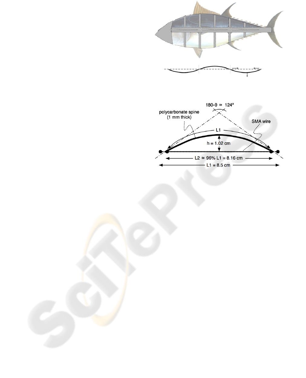
total of three bendable segments (cf. Figure 1).
The fish is formed by a continuous structure made
of polycarbonate 1 mm thick, which represents the
fish backbone and spines. This material has been cho-
sen for its temperature resistance, impact resistance
and flexibility. Additional supporting structure made
of PVC is employed to support the silicon-based skin
of the robot. The overall length of the fish is 30 cm
(not including the caudal fin). Along the backbone,
six SMA actuators are used to bend the body. Their
length is 1/3 body length (i.e. 8.5cm, not counting
the caudal fin and the head) and are positioned in
pairs, in such a way to produce an antagonistic move-
ment. Thanks to this arrangement, the body segments
can bend up to ≈ 30 degrees. The diameter size of
the wires has been chosen as a trade-off between cur-
rent consumption, pull force and contraction time. We
have adopted a SMA with a diameter size of 150µm
that has a pull force of 230 grams, a consumption of
250 mA at room temperature, and a nominal contrac-
tion time of 1 second. Such contraction time allows
an undulation frequency that is enough for producing
motion in water.
2.1 Shape Memory Alloys
SMAs are materials capable of changing their crys-
tallographic structure (from austensite and marteniste
Figure 1: Lateral and upper view of the deformable struc-
ture. Note the location of the SMA wires along the body.
Figure 2: Principle of the bendable structure. The SMA
wire is parallel to the spine segment. As it contracts, it
causes the polycarbonate strip to bend.
phases), due to changes in temperature. When an
SMA wire is subjected to an electrical current, Joule
resistive heating causes the SMA actuator to contract.
SMAs have the advantage that they work at low cur-
rents and voltages, are extremely cheap and are easily
available commercially. Nitinol, one of the most com-
mercially available SMAs, is an alloy of nickel and
titanium (NiTi). It is characterized by a high recovery
stress (> 500MPa), low operational voltage (4 −5 V ),
a reasonable operational strain (≈ 4%) and a long life
(up to 10
6
cycles).
The behavior of SMAs is more complex than
many common materials: the stress-strain relation-
ship is non-linear, hysteretic, exhibits large reversible
strains, and it is temperature dependent. For this rea-
son, a low-level control electronics has to be designed
in order to have a position control close-loop precise
enough for the application at hand. An important
characteristics of SMAs is that they can also be used
as sensors. In fact, once heated applying a given cur-
rent, one can measure their resistance and calculate
the actual percentage of shrinking. This measurement
can be used as feedback for achieving precise position
control.
ICINCO 2010 - 7th International Conference on Informatics in Control, Automation and Robotics
148
3 SMA CONTROL
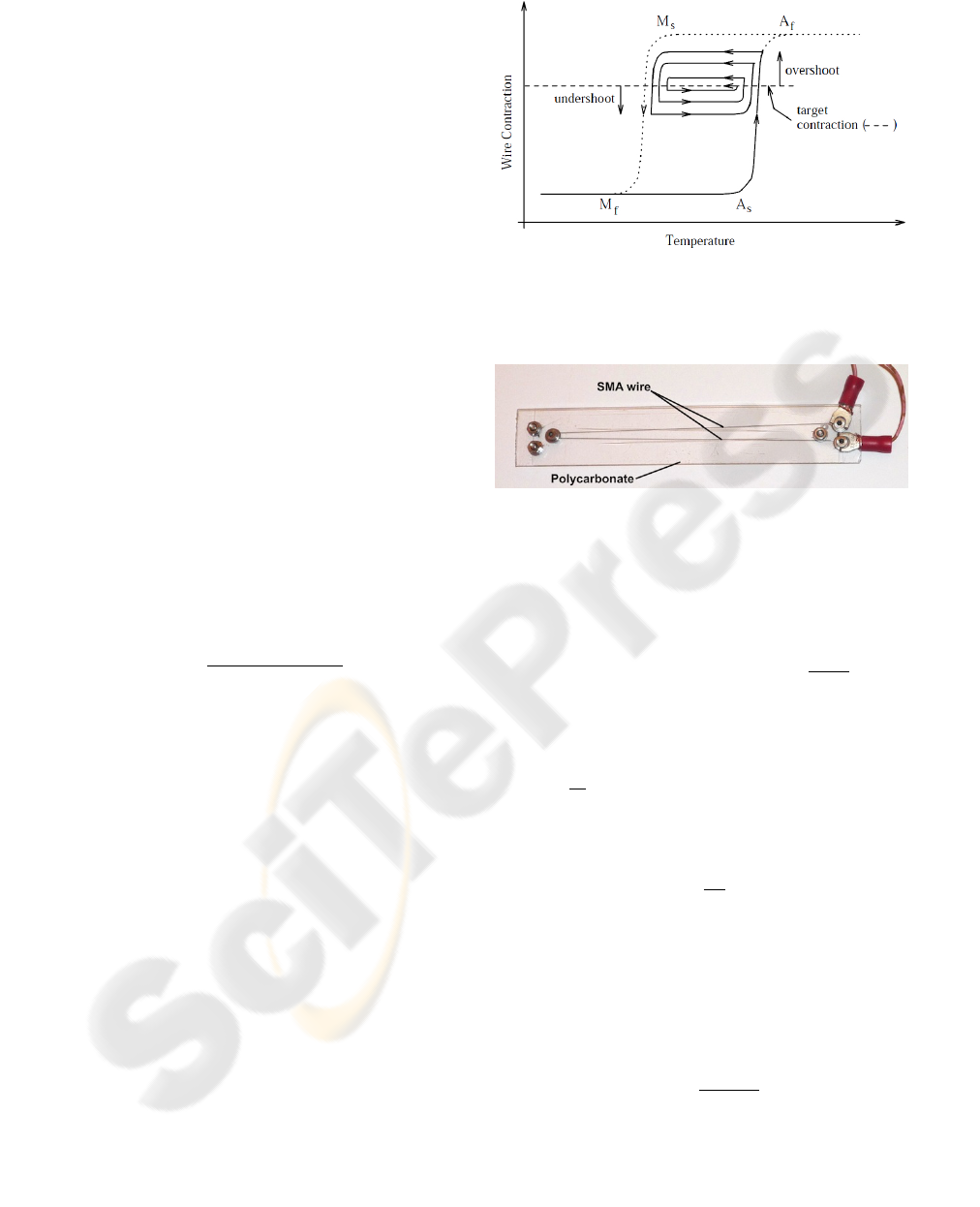
The control accuracy of smart actuators such as SMAs
is limited due to their inherent hysteresis nonlineari-
ties (see Figure 3) with a local memory. The exis-
tence of minor loops in the major loop because of a
local memory also makes the mathematical model-
ing and design of a controller difficult for SMA ac-
tuators. Therefore, to enhance the controllability of
a smart actuator, the Preisach hysteresis model (Vis-
intin, 1995) has emerged as an appropriate behavioral
model. Nevertheless, the modeling is difficult and the
model equation remains complex. So even though
this model is commonly used (Choi et al., 2004), the
use of a heat transfer model and sensor hardware has
also been proposed.
As pointed out earlier, SMAs provide the possibil-
ity to develop controller systems without sensor hard-
ware. The detection of inner electrical resistance al-
lows to regulate the actuator movement (Ikuta et al.,
1988). The method consists in measuring the elec-
trical resistance of an SMA element (Teh, 2008) as
a form of temperature measurement. An advantage
of this method is that the hysteresis on the resistance
curve is smaller than the hysteresis on the temperature
curve, which makes the linear approximation more
accurate.
The maximum contraction of the wire can be mea-
sured as
∆L
A
f
=
R
SMA
M f
− R
SMA
A f
L
R
, (1)
where R
SMA
M f
(Ω) is the SMA resistance in marten-
site finish temperature (relaxed SMA), L
R
(Ω/m) is
the linear resistance and R
SMA
A f
(Ω) is the resistance
at austenite finish temperature (i.e. at maximum con-
traction).
Figure 5 shows the performance of a mock-up for
a current of 350mA. The angle shown in the figure is
in good accordance with the theoretical value of 28
◦
(cf. Figure 2). Note that the wires’ speed and strain
contraction depends on how fast and by how much the
wire temperature is increased. In our tests, we have
verified that SMAs wires can be fed with a current
of up to 500mA without compromising their behavior,
achieving faster response and higher percentages of
contraction.
3.1 Controller Tuning
In order to tune the control system, we set up a mock-
up of a segment of the fish’s backbone, corresponding
to a 10 ×2cm stripe of 1mm thick polycarbonate, with
a 174mm long SMA wire in a V-shaped configuration,
in order to double the pull force (see Figure 4).
Figure 3: Histeresis of the SMA. (A
s
, the austenite start
temperature; A
f
, the austenite finish temperature; M
s
, the
martensite start temperature; and M
f
, the martensite finish
temperature).
Figure 4: The test mock-up.
For the control, we used a PID (proportional-
integral-derivative) controller, which responds to the
equation
u(t) = K
p
e(t) + K
i
Z
t
0
e(t)dt +K
d
de(t)
dt
, (2)
where e(t) is the signal error and u(t) is the con-
trol input of the process. K
p
,K
i
,K
e
are the propor-
tional, integrative and derivative gains. Then by pos-
ing K
i
=
K
p
T
i
,K
d
= K
p
T
d
, where T
i
is the integral time
constant and T
d
is the derivative time constant, the
PID controller can be written in the s domain as
U(s) = K
p
1 +
1
T
i
s
+ T
d
s
E(s). (3)
Following Ziegler-Nichols, we have tuned the val-
ues to the three parameters (K
p
,T
i
,T
d
) of the PID con-
troller based on the analysis of the open and close
loop of the system to be controlled. The dynamics
behavior of the system is defined using the following
first-order linear transfer function:
G(s) =
K
0
e
−sτ
0
1 − sγ
0
, (4)
where the coefficients K
0
,τ
0
and γ
0
are obtained from
the response of the open loop system to a step in-
put. Starting from the stabilized system at y(t) = y
0
to u(t) = u
0
, a step input is applied from u
0
to u
1
.
SMA CONTROL FOR BIO-MIMETIC FISH LOCOMOTION
149