
NETWORK IN A BOX
Franc¸ois Gagnon
School of Computer Science, Carleton University, Ottawa, Canada
Babak Esfandiari and Tomas Dej
Department of Systems and Computer Engineering, Carleton University, Ottawa, Canada
Keywords:
Network experiment, Virtualization, Automatization.
Abstract:
VNEC (Virtual Network Experiment Controller) is an open source tool for specifying and executing network
experiments in a virtual environment. The user first describes the network topology, and then provides the
tasks that should be performed by the hosts, together with their execution order. Next, VNEC initializes the
environment by configuring and powering on the corresponding virtual machines to match the desired network
topology. Finally, commands are dispatched to the proper virtual machines in the specified order. VNEC can
hence be used for many types of network experiments. This paper presents the architecture of VNEC and
discusses its implementation.
1 INTRODUCTION
Virtualization technologies such as VMWare offer the
necessary components to set up a virtual environment
where experiments can be safely executed at a low
cost. However, one has to either setup and execute the
experiment manually or develop his own controller.
This paper describes VNEC (Virtual Network Ex-
periment Controller), an open source tool
1
that al-
lows the user to easily specify and execute network
experiments. The main applications driving the de-
velopment of VNEC are network experiments focus-
ing on the actions performed by the hosts. Sensi-
tive experiments (e.g., virus propagation (Twycross
and Williamson, 2003) and attack scenarios (Mas-
sicotte et al., 2005)) and data collection experi-
ments (e.g., operating system fingerprinting (Gagnon
et al., 2007) and target behavioral analysis (Massi-
cotte et al., 2006)) are a few examples. These appli-
cations have three important requirements:
• Execute the experiment in a confined environ-
ment, to avoid infecting physical machines with
viruses.
• Execute the experiment in a sanitized environ-
ment, to ensure that the outcome of an experiment
is not affected by the side effects of a previous ex-
periment.
1
http://vnec.sourceforge.net
• Allow the use of a wide variety of guest operating
systems, to collect data across a wide spectrum of
targets.
The rest of the paper is structured as follows: Sec-
tion 2 discusses related work in the area of virtual-
ization controllers. Section 3 briefly presents VNEC
from a user point of view, i.e., the different specifica-
tion steps; a more complete description can be found
in (Gagnon et al., 2008). Section 4 details VNEC’s
architecture, discussing how the features are imple-
mented. Finally, a discussion and some pointers to-
wards future work conclude the paper.
2 RELATED WORK
Some tools similar to VNEC already exist, but to our
knowledge none of them are as flexible nor as general.
VIX is an API developed by VMWare to provide
some control over their virtual machines (e.g., power
up, file copying, command execution). Unlike VNEC,
VIX is not a controller; it simply provides some tools
helping one to build his own controller. More im-
portantly, the VIX functions allowing communication
with a VM only work if the guest operating system
(the OS running inside the VM) is a recent version of
Linux or Windows. This is a major limitation, since
commands can only be passed to a small subset of
VMs.
55
Gagnon F., Esfandiari B. and Dej T. (2010).
NETWORK IN A BOX.
In Proceedings of the International Conference on Data Communication Networking and Optical Communication Systems, pages 55-60
DOI: 10.5220/0002891600550060
Copyright
c
SciTePress
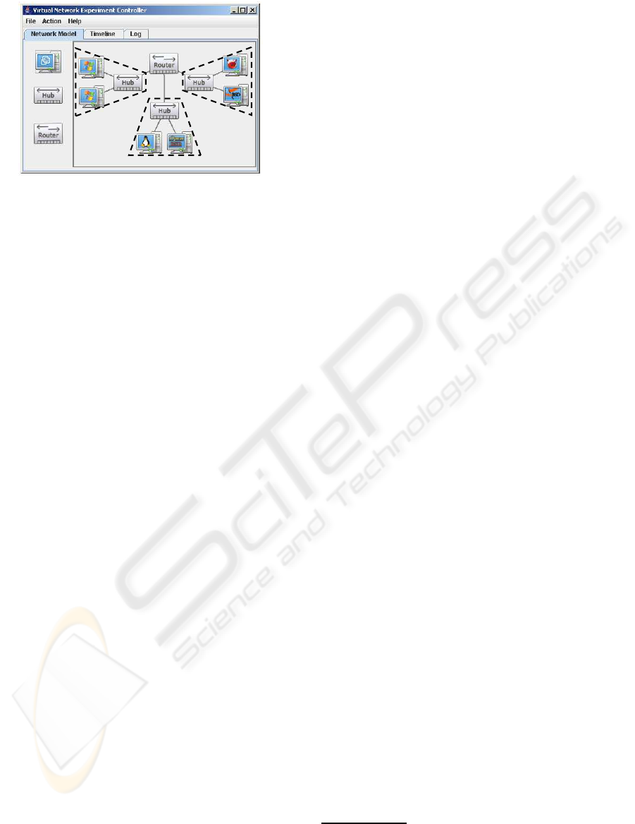
127.0.0.1
VMWare
192.168.1.2
VirtualPC
192.168.1.2
VMWare
Figure 1: Screenshot of VNEC - Network specification.
The VNUML tool (Virtual Network User Mode
Linux) is a controller for the UML virtualization tech-
nology. However, since UML only supports Linux
OSes, VNUML is also very limited in scope.
Network simulation tools such as NS2 (Is-
sariyakul and Hossain, 2009) and OPNET are very
popular for network experiments. However, these
network simulators and VNEC are quite different in
scope. OPNET’s focus is at the packet level (proto-
cols, delays, sequencing, routing, ...), which makes
it not well-suited for host-centered experiments (OS
fingerprinting, virus propagation, ...). VNEC’s fo-
cus is at the host-level, which makes it a good frame-
work of host-behavior experiments. But, VNEC does
not provide control at the packet level (e.g., delays,
packet-loss).
3 USING VNEC
From the user’s point of view, using VNEC consists
of three steps: network specification, task workflow
specification, and experiment execution (see (Gagnon
et al., 2008) for more details).
3.1 Network Specification
Figure 1 depicts the network specification environ-
ment of VNEC. The network specification phase con-
sists of three parts:
• Creating the set of components (computers, hubs,
and routers) using a drag-and-drop interface.
• Specifying the network topology by connecting
the components.
• Associating each computer to a virtual machine
(from a set of pre-existing VMs).
3.1.1 Network Specification Verification
Once the network specification is complete, and be-
fore moving on to the task workflow specification
step, VNEC performs a series of verifications to
validate the network topology provided. Basically,
VNEC makes sure it has sufficient resources to vir-
tualize the given network. The rules regarding net-
work specification are listed here; their justifications
will be explained in Section 4.2 where we discuss the
implementation of VNEC.
Topology Rule 1 (Host Connection). Each host has
at most one connection. For simplicity, we currently
assume that each host VM has a single network inter-
face.
Topology Rule 2 (Router Connection). Each router
has at most three
2
connections.
Topology Rule 3 (Homogeneous Segments). A net-
work segment must contain VMs from the same virtu-
alization technology and located on the same phys-
ical machine. In Figure 1, the VMs in the right
segment are VMWare and are located on the remote
host 192.168.1.2, the VMs in the middle segment are
VMWare as well but are located on the local host, fi-
nally, the VMs in the left segment are Virtual PC and
are located on 192.168.1.2.
Topology Rule 4 (Number of Segments). There can
be no more than seven
3
network segments for a given
virtualization technology on a given physical host.
3.2 Task Workflow Specification
The task workflow specification step allows the
user to assign tasks to be executed by the virtual
machines and to specify their execution order. The
task workflow is a directed acyclic graph where each
node corresponds to a task. A task is to be executed
when all its parent tasks are completed. A task
workflow reads from left to right; a circle represents
the execution of a task by a single given VM, while
a rectangle stands for the execution of a task by a
group of VMs.
There are two types of tasks. Command tasks
(e.g., create file, delete file, ping, open telnet connec-
tion) are executed by the VMs, while control tasks
(e.g., power on, shut down, take snapshot, revert
to snapshot) are performed by VNEC’s engine to
modify the state of a virtual machine.
2
VMWare VMs can have at most three network inter-
face.
3
VMWare Workstation offers seven virtual networks
(VMNets).
DCNET 2010 - International Conference on Data Communication Networking
56

4 VNEC’S ARCHITECTURE
This section provides both a general overview of
VNEC’s architecture and detailed descriptions re-
garding the implementation of the main features.
4.1 Overview
VNEC consists of four modules:
• vnec-master
• vnec-slave
• vnec-router
• vnec-taskRunner
VNEC is deployed on a set (possibly a singleton) of
physical machines. The local machine runs vnec-
master and is the single control point for the user, i.e.,
by providing the GUI described in Section 3. The re-
mote computers (and optionally the local one as well)
run vnec-slave (see Example 1).
Example 1 (Master/Slave Interaction). The experi-
ment shown in Figure 1 relies on two physical com-
puters: 127.0.0.1 and 192.168.1.2. In that particu-
lar case, 127.0.0.1 is running vnec-master and both
127.0.0.1 and 192.168.1.2 are running vnec-slave.
vnec-slave is mainly responsible for the interac-
tion (remote or not) between vnec-master and the
virtual machines, controlling them through different
technologies and forwarding tasks to be executed (see
Example 2).
Example 2 (Slave/VM Interaction). The remote
computer 192.168.1.2 in the experiment of Figure 1
has to control both VMWare and Virtual PC VMs
through its instance of vnec-slave.
Each physical host running vnec-slave makes its
VMs available for the experiment. Virtual machines
are of one of two types: router or host. Router
VMs (running the vnec-router program) provides ba-
sic routing functionalities (e.g., packet forwarding,
ARP resolution, . . . ) as well as other utilities more
specific to VNEC, such as dispatching task to VMs
(see Section 4.2.3). Host VMs (running the vnec-
taskRunner program) are used to execute tasks.
The example below provides an overview of the
interaction between the different modules.
Example 3 (VNEC Overview). If vnec-master
needs VM v to execute task t (e.g., ping 10.92.1.4) it
will start by establishing on which physical host v is
located. Then, it will contact the vnec-slave running
on that host and request it to forward the task t to v.
vnec-slave will first identify which router VM is on the
same segment as v and then will ask the router to dis-
patch task t to v. The router will contact v and request
the execution of t. v will execute the ping task, possi-
bly relying on routers to communicate with 10.92.1.4.
Once v finishes the task, it notifies the router, provid-
ing the task outcome (e.g., how many ping requests
were successful). The router forwards the outcome to
vnec-master by going through vnec-slave.
In the above example, one could wonder why
vnec-slavegoes through a router to communicate with
the target VM v. There are two reasons:
• For security purpose, we make sure that none of
the VMs can communicate with a physical host
via a network connection. This is very important
to ensure that the network experiment is confined
into the virtual environment (e.g., to avoid a virus
from propagating into the physical network). The
physical machine, i.e., vnec-slave, can only com-
municate with router VMs via a shared folder, see
Section 4.2.3.
• To support a wide variety of OSes, we avoid com-
municating with host VMs throughshared folders.
We use this communication mechanism only with
router VMs.
4.2 Implementation
Below we discuss how the main features of VNEC are
implemented.
4.2.1 Multi-virtualization Technologies
We faced two challenges when implementing the
multi-virtualization technology feature: VM inter-
communication and control. The former is addressed
by the additional abilities of our routers, see Section
4.2.3. The latter mainly requires vnec-slave to know
how to perform specific control actions on a VM with
respect to different virtualization technologies. The
control actions required are: configure virtual net-
work, power on, and power off.
For VMWare, the task was quite easy. Configur-
ing the virtual network of a VM, i.e., to set its vir-
tual network interface on a specific VMNet, simply
requires modifying an entry (e.g., ethernet0.vnet =
”VMnet2”) into the “.vmx” text-based configuration
file of that VM. Power on and power off are both
directly supported through the command line. We
also support take snapshot and revert to snapshot for
VMWare only.
For Virtual PC, changing the network configura-
tion is achieved by modifying the “.vmc” configurati-
NETWORK IN A BOX
57

on file, which is in xml format. Powering on is also
supported by the command line, but powering off is
not. Our current workaround is to kill the Virtual PC
process, resulting in powering off all Virtual PC VMs
running on a physical host simultaneously.
On top of controlling the VMs, we need two fea-
tures from each virtualization technology: a shared
folder and state saving/resuming capabilities. The
shared folder provides a communication mechanism
between vnec-slave and the routers, see Section 4.2.3.
State saving/resuming is essential to make sure that
the effects of an experiment are not carried over to
the next one and that the VMs can always be powered
on in a specific state, i.e., where the vnec-taskRunner
is active and ready to receive tasks.
VMWare already provides these two features.
Shared folders can be enabled on guest VMs running
recent versions of Windows and Linux, through the
installation of VMWare Tools
4
. This is sufficient as
we only need shared folders with routers. The snap-
shots features of VMWare allows us to always power
on a VM at a specific state (e.g., where the vnec-
taskRunner process is running) and automatically re-
vert back to that state when the VM is powered off.
For Virtual PC, some “hacking” is again required.
Shared folders are no problem with some VMs (suf-
ficient for our routers) through the installation of Vir-
tual Machine Additions
4
. However, Virtual PC only
provides a single saved state and since we close VMs
by killing the process, they cannot automatically be
brought back to their saved state on shutdown. We
circumvent this problem by copying the “.vmc” (con-
taining the vm configuration)and “.vsv” (used to store
the vm state) files when the VM is powered on and
restoring the copied files once the VM is powered off.
Together with the “undo disk” feature, which allows
changes to the VM to be written into a separate file
(which is discarded in our case), we can havethe same
state every time we power on a VM.
4.2.2 Multi-host
Deploying a virtual network across multiple physical
computers is not trivial, especially with the require-
ment that the virtual network be closed from the phys-
ical world (for security reasons) yet remain fully con-
nected. Section 4.2.3 discusses how the vnec-router
module ensures the connectivity of the virtual net-
work. Here we provide more details regarding the
interaction between the physical hosts, i.e., between
the vnec-master and vnec-slave modules.
vnec-master and vnec-slave communicate to-
gether through Java RMI. Upon startup, vnec-master
4
A set of services and drivers enhancing the capabilities
of the guest OS.
reads a configuration file to obtain the list of physi-
cal hosts that can be used for the experiment. Each
physical host is assumed to be running an instance of
vnec-slave. vnec-master first tests if it can communi-
cate with every listed slave. Then, vnec-master builds
the set of VMs available for the experiment by asking
each slave to provide its set of VMs. When the user
starts the experiment, vnec-master informs the corre-
sponding slaves. Moreover, the master registers itself
both as a TaskListener and a PacketListener with all
slaves. The TaskListener interface allows a slave to
update its master regardingthe progress of a task (e.g.,
task completed, outcome available, ...). The Pack-
etListener interface allows a slave to notify its master
that a packet needs to be forwarded to another slave.
During the experiment, the master dispatches tasks to
be executed in the realm of a specific slave. Finally,
once the experiment completes, the master notifies all
the slaves to make sure they are ready to accept a new
experiment.
The master can request a slave to forward a spe-
cific packet to a specific VM. To make sure no secu-
rity breach is created when such a packet transits on
the physical network, it is encrypted using a randomly
generated symmetric key
5
. As a result, it is not pos-
sible for someone (e.g., a virus designer) to generate
a packet in the virtual network such that the data cor-
responding to that packet transiting on the physical
network will actually be malicious.
4.2.3 Router
A router is a VM with three network interfaces run-
ning the vnec-router module. Three is the maximum
number of network interfaces allowed for a VM in
VMWare Workstation and we adopt it as our stan-
dard
6
, hence Topology Rule 2. Routers route traffic
from one network interface to another, but there is
much more to them.
First, routers are responsible for forwarding tasks
from the vnec-slave module running at the physical
level to the vnec-taskRunner module running inside
the host VMs. To perform this, a router monitors a
specific folder shared with its physical host. When-
ever a task needs to be dispatched, it is written in
that folder (by vnec-slave). The router reads the task,
sends it to the corresponding host VM, and writes
back the outcome in the folder for the vnec-slave
to handle. To router communicates with host VMs
through a Java RMI interface implemented by all the
5
A new symmetric key is randomly generated for each
packet and is sent to the receiving host before the encrypted
packet.
6
Virtual PC allows fours network interfaces, but for sim-
plicity we restrict all routers to three.
DCNET 2010 - International Conference on Data Communication Networking
58
vnec-taskRunners.
Basic routing functionalities are not sufficient for
VNEC. For instance, for security reasons there can
be no direct network links between two VMs run-
ning on different physical hosts. Similarly, there can
be no network links between a VMWare VM and a
Virtual PC VM, even if they are on the same phys-
ical host. To circumvent this and still provide full
virtual network connectivity, VNEC relies on a spe-
cial feature of vnec-router called external interface.
On top of being able to route a packet from a virtual
network interface to another, a router VM can route
a packet from a virtual network interface straight to
vnec-slave, and vice-versa. Then, vnec-slave has the
ability to either give the packet to a different router (to
allow router communication across different virtual-
ization technologies on the same physical computer),
or to pass it to vnec-master who will forward it to
the proper vnec-slave (to allow router communication
across different physical computers).
4.2.3.1 Network Topology Adjustments. In or-
der for an experiment to run properly, some modifica-
tions might be required on the initial network topol-
ogy provided by the user. For instance, VNEC must
be able to dispatch tasks to any host VM. Moreover,
any pair of VMs must be able to communicate to-
gether. To achieve this, there must be at least one
router VM per virtual network segment. As a con-
sequence, VNEC will sometimes automatically add
routers, see Example 4.
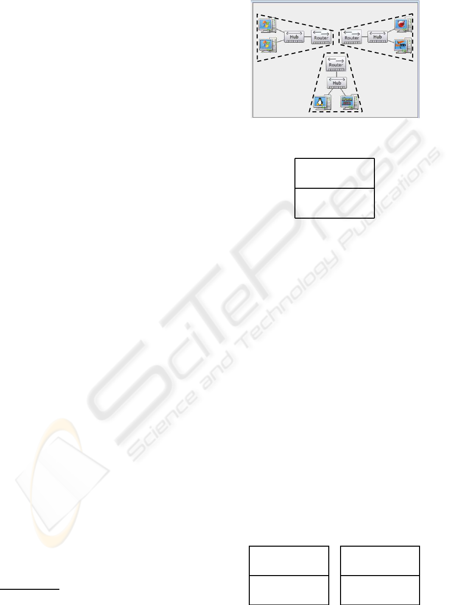
Example 4 (Automatically Adding Routers). The
network provided by the user in Figure 1 does not
respect the one router per virtual segment require-
ment; there are three virtual segments and only one
router. VNEC addresses this by automatically adding
new routers. In the case of Figure 1, VNEC will
replace the single router by three different ones: A
VMWare router on 192.168.1.2 for the right segment,
a VMWare router on 127.0.0.1for the middle segment,
and a Virtual PC router on 192.168.1.2 for the left
segment, see Figure 2.
The algorithm to add routers is described below.
We rely on a segment-based data structure where a
network is a set of segments and a segments is a set
of routers and a set of VMs. Each router has a routing
table
7
saying which interface to use to reach a spe-
cific host. Moreover, each router usually appears in
more than one segment, but at most three (see Topol-
ogy Rule 2), and each router interface is associated to
7
Currently, VNEC computes a static routing table based
on the initial network topology.
192.168.1.2
VirtualPC
192.168.1.2
VMWare
127.0.0.1
VMWare
1
2
3
Figure 2: Routers added.
Table 1: Initial routing table.
R
1
destination interface/
segment
10.92.1.21 s
1
10.92.1.22 s
2
10.92.1.23 s
3
one segment. If router R
1
belongs to two incompati-
ble segments s
1
and s
2
(i.e., segments not on the same
physical machine or not using the same virtualization
technology) we replace R
1
in s
2
with a new router R
2
.
Then, the routing tables of both R
1
and R
2
are ad-
justed, see Table 1 and Table 2. R
1
is adjusted as fol-
lows: every communication going to s
2
is now routed
through an external interface (to the vnec-slave) the
rest remains unchanged. R
2
is adjusted as follows:
every communication going to s
2
remains unchanged,
everything else is now routed towards the vnec-slave.
4.2.3.2 Routing Packets. Now that each virtual
segment has its own router, VNEC can dispatch tasks
to any host VM (through its router) and all VMs can
communicate with each other on the network. Exam-
ple 5 illustrates how packets are routed across VMs
sitting on different physical hosts.
Example 5 (Packet Routing in VNEC). Based on
the modified network topology of Figure 2, assume
that the Linux VM wants to send an Echo request
packet to 10.92.1.6 (one of the Windows VM). Linux
first sends an ARP request to obtain the MAC address
associated with 10.92.1.6. Since the target is not lo-
cated on the same segment, Router2 will respond to
Table 2: Splitted routing table.
R
1
R
2
destination interface/ destination interface/
segment segment
10.92.1.21 s
1
10.92.1.21 Ext
10.92.1.22 Ext 10.92.1.22 s
2
10.92.1.23 s
3
10.92.1.23 Ext
NETWORK IN A BOX
59

that ARP request. Then, Linux sends the Echo re-
quest to 10.92.1.6 with Router2’s MAC address. The
router receives the packet and decide, based on its
routing table, that the packet has to be forwarded on
its external interface. The packet is then passed on
to the slave running on 127.0.0.1 (this is achieved by
using a shared folder). Because the source and desti-
nation are not located on the same host, the slave then
forwards the packet to its master. The master trans-
fers the packet to the slave running on 192.168.1.2.
That slave will then transmits the packet to a router
on the same segment as 10.92.1.6 (again via a shared
folder), here Router3. Finally, Router3 will forwards
the packet to the destination VM.
4.2.4 Hub
To reflect real networks, we want the network traffic
going through a specific network segment to reach all
the virtual machines of that segment, i.e., hubs broad-
cast the traffic. This is exactly the behaviorof a virtual
network segment. In VMWare, the VMs attached to
VMNet3 will received all the packets passing in VM-
Net3. A similar feature is available in Virtual PC by
using loopback adapters. In VMWare there are seven
available VMNets by default. As a consequence, we
limit the number of network segments to seven for a
given physical host and a given virtualization technol-
ogy, hence Topology Rule 4.
To make sure traffic is broadcasted on a segment,
we verify that all the VMs on a network segment cor-
respond to the same virtualization technology and are
located on the same physical host, hence Topology
Rule 3.
5 DISCUSSION & FUTURE
WORK
VNEC is an open source controller for virtual net-
works, available at http://vnec.sourceforge.net. It al-
lows the user to specify a network experiment (net-
work topology and task workflow) through a graphi-
cal interface. It automatically configures and controls
the underlying VMs to perform the experiment. To
provide a wide selection of virtual machines, VNEC
is designed to support multiple virtualization tech-
nologies. To avoid the need for expensive dedicated
computers, VNEC allows the user to distribute his ex-
periments across multiple physical computers.
The VNEC project can be extended in several
ways. We consider the following for the near future:
• Design an XML-based language to save/load ex-
periments. This could also be used as a scripting
language to avoid relying solely the GUI.
• Support more virtualization technologies: we are
currently studying VirtualBox and UML. Adding
a new technology simply requires to program an
interface between VNEC and the actual virtual-
ization program.
• Develop a workflow analyzer to detect basic
anomalies in an experiment, e.g., if a VM is sup-
posed to execute a command task before it is pow-
ered on.
REFERENCES
Gagnon, F., Dej, T., and Esfandiari, B. (2008). VNEC - A
Virtual Network Experiment Controller. Proceedings
of the 2nd International Workshop on Systems and Vir-
tualization Management (SVM’08), pages 119–124.
Gagnon, F., Esfandiari, B., and Bertossi, L. (2007). A Hy-
brid Approach to Operating System Discovery Us-
ing Answer Set Programming. Proceedings of the
10th IFIP/IEEE Symposium on Integrated Manage-
ment (IM’07), pages 391–400.
Issariyakul, T. and Hossain, E. (2009). Introduction to Net-
work Simulator NS2. Springer.
Massicotte, F., Couture, M., , and Montigny-Leboeuf, A. D.
(2005). Using a VMware Network Infrastructure to
Collect Traffic Traces for Intrusion Detection Evalua-
tion. Proceedings of the 21st Annual Computer Secu-
rity Applications Conference (ACSAC’05).
Massicotte, F., Gagnon, F., Couture, M., Labiche, Y., and
Briand, L. (2006). Automatic Evaluation of Intru-
sion Detection Systems. Proceedings of the 2006
Annual Computer Security Applications Conference
(ACSAC’06).
Twycross, J. and Williamson, M. M. (2003). Implementaing
and Testing a Virus Throttle. Proccedings of the 12th
USENIX Security Symposium.
DCNET 2010 - International Conference on Data Communication Networking
60
