
ADAPTIVE EXECUTION OF SOFTWARE SYSTEMS ON PARALLEL
MULTICORE ARCHITECTURES
Thomas Rauber
Department of Computer Science, University of Bayreuth, Bayreuth, Germany
Gudula R¨unger
Department of Computer Science, Chemnitz University of Technology, Chemnitz, Germany
Keywords:
Parallel execution, Multicore systems, Incremental transformation, Transformation toolset, Dynamic schedul-
ing.
Abstract:
Software systems are often implemented based on a sequential flow of control. However, new developments
in hardware towards explicit parallelism within a single processor chip require a change at software level
to participate in the tremendous performance improvements provided by hardware. Parallel programming
techniques and efficient parallel execution schemes that assign parallel program parts to cores of the target
machine for execution are required.
In this article, we propose a design approach for generating parallel software for existing business software
systems. The parallel software is structured such that it enables a parallel execution of tasks of the software
system based on different execution scenarios. The internal logical structure of the software system is used
to create software incarnations in a flexible way. The transformation process is supported by a transformation
toolset which preserves correctness and functionality.
1 INTRODUCTION
Many advances in software technology and business
computing are enabled by a steady increase in mi-
croprocessor performance and manufacturing tech-
nology. The performance increase will continue dur-
ing the next years (Kuck, 2005; Koch, 2005). How-
ever, technological constraints have forced hardware
manufacturersto consider multicore design to provide
further increasing performance. For these multicore
designs, multiple simple CPU cores are used on the
same processor die instead of a single complex CPU
core. It is expected that within a few years, a typical
desktop processor provides tens or hundreds of exe-
cution cores which may be configured according to
the needs of a specific application area (Kuck, 2005).
The design change towards multicore processors
requires a fundamental change in software develop-
ment, since the computing power of the new proces-
sors can only be utilized efficiently if the application
program provides coordination structures which en-
able a mapping of different execution threads to dif-
ferent cores. A large variety of parallel programming
languages, scheduling algorithms, and programming
techniques have already been proposed, but they often
require the specification of low-level synchronization
and usually parallelization operations that are error-
prone and require a lot of programming experience
to get correct and efficient programs. It is often ar-
gued that more abstract features need to be developed
and integrated into programming languages and sys-
tems to facilitate the use of parallelism (Sutter and
Larus, 2005; Sutter, 2005). This is also important for
business software and the new development towards
multicore provides new challenges and opportunities.
In particular, the use of parallelism allows the inte-
gration of new functionalities, e.g., by running useful
tasks continuously, like an automatic backup utility or
statistics, offering more potential for real-time infor-
mation on demand (Reinders, 2006).
The contribution of this paper is to propose an ex-
ecution environment for business software which en-
ables a parallel execution on arbitrary multicore plat-
forms. The approach decouples the parallel execution
from the specification of the business logics of the
software systems, so that the programmer can con-
191
Rauber T. and Rünger G. (2010).
ADAPTIVE EXECUTION OF SOFTWARE SYSTEMS ON PARALLEL MULTICORE ARCHITECTURES.
In Proceedings of the 12th International Conference on Enterprise Information Systems - Information Systems Analysis and Specification, pages
191-198
DOI: 10.5220/0002894901910198
Copyright
c
SciTePress
centrate on the requirements of the software system.
A runtime system performs the actual mapping of the
software computations to the execution platform. For
a different platform, a different mapping may lead to
the best execution. The specific approach comprises
the following novel issues:
• We propose to structure business programsas a set
of cooperating tasks that are brought to execution
by a specialized runtime system.
• We propose a programming technique to imple-
ment such programs and present a scheduling
technique that assigns parallel computations to
cores at runtime.
• We propose an interactive transformation process
organized in several steps, which enables interac-
tive decisions for forming and orchestrating the
tasks. The transformation process is supported by
a transformation toolset.
In summary, a flexible and adaptive execution
scheme results, which can deal with dynamic, adap-
tive, and long-running software requirements, cap-
turing typical characteristics of software systems for
business computing.
The rest of the paper is organized as follows: Sec-
tion 2 presents the execution environment proposed
for executing business software systems. Section
3 presents the priority-based scheduling algorithm.
Section 4 outlines the transformation process and the
architecture of the transformation toolset. Section 5
discusses related work. Section 6 concludes.
2 EXECUTION ENVIRONMENT
In this section, we propose an execution environment
for an adaptive execution of business software sys-
tems on multicore architectures.
2.1 Overview
The execution environment is based on a decomposi-
tion of the computations of the software system into
tasks. This decomposition can be supported by a
transformation system as outlined in Section 4. In
the following, we assume that the decomposition into
tasks is available. Each task has a unique identifier
(TID - task identifier) and specifies the computations
to be performed. Moreover, each task provides an in-
terface specifying the input data of the task as well as
the output data which results by executing the task.
Input and output data may cause dependencies be-
tween tasks: if a task B uses data computed by task A,
then there is a dependence A → B. In this case, B can-
not be executed before the executionof A has been fin-
ished. Dependencies between tasks can be illustrated
by a task dependence graph (TDG). The nodes of the
TDG are the tasks executed by the business software
system. The edges of the TDG represent the depen-
dencies between the tasks.
During the execution of the software system, tasks
can be dynamically created. This can happen accord-
ing to an interactive request by the user of the soft-
ware system. New tasks can also be created during
the execution of other tasks according to the needs
of the computations requested. Thus, the task struc-
ture is not fixed when starting the software system,
but evolves dynamically, and so does the TDG.
As described above, dependencies in the TDG re-
strict the execution order of tasks, requiring a sequen-
tial execution in the presence of a dependency. On
the other hand, two or more tasks can be executed in
parallel if there are no dependencies between them.
This gives room for an efficient use of multiple cores
as they are provided by current and future multicore
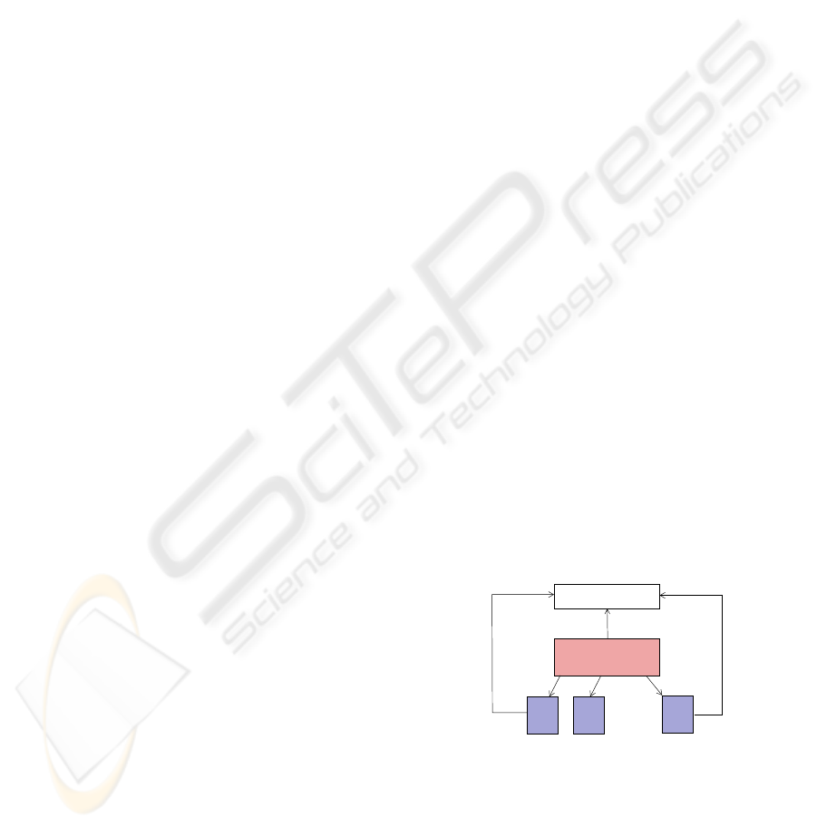
processors. In particular, the execution environment
uses a runtime system with several components. The
central component is a task distribution engine (TDE)
which controls the dynamic deployment of tasks to
cores for execution. The tasks that are ready for ex-
ecution are stored in a special data structure from
which they are retrieved by the TDE, see Fig. 1 for
an illustration. During the execution of a task, new
tasks may be generated. If these are ready for exe-
cution, they are inserted into the set of ready tasks.
If newly created tasks are not ready for execution be-
cause, e.g., they must wait for an external event or
for the arrival of data, they are inserted into a pool of
pre-tasks. They are moved to the set of ready tasks as
soon as all their requirements are fulfilled.
insert
insert
ready tasks
task distribution
engine
retrieves
1
core
core
2
. . .
core
n
deployment
. . .
Figure 1: Illustration of the functionality of the task distri-
bution engine.
3 ADAPTIVE SCHEDULING
In this section, more details about the scheduling of
tasks by the TDE are described. In particular, the use
of the priority vector is discussed and two scheduling
ICEIS 2010 - 12th International Conference on Enterprise Information Systems
192

modes for the TDE and their corresponding schedul-
ing algorithms are presented.
3.1 Priority Vector and Task Status
The scheduling of tasks includes decision rules for the
assignment of tasks to specific cores at a specific time.
The decisions are usually based on a cost measure ap-
propriate for the specific situation.
In this article, we consider long-running applica-
tion programs with a dynamic creation of tasks during
runtime. For this kind of application, we propose a
new cost measure. The cost of a task M is captured in
a priority vector
pr(M) = (RD(M),PR(M), HR(M))
comprising informationabout the status RD(M) of the
task, a priority information PR(M), and information
about hardware restrictions HR(M) for the execution
of M. In the following, we describe which type of
information can be captured in the priority vector.
Ready States. A task can be in one of two possi-
ble states: If all constraints and requirements are ful-
filled, a task is ready to be executed (i.e., RD(M) = 1)
and can be selected by the scheduling algorithm for
an actual execution. If there are constraints or re-
quirements which are not fulfilled, a task is not ready
for execution (i.e., RD(M) = 0) and is currently not
considered by the scheduling algorithm. Tasks can
change their ready state during the runtime of the ap-
plication. When a task M is created, its state is set to
RD(M) = 0. This is done for the tasks started at the
beginning as well as for the tasks being created during
runtime by another task. Although these newly cre-
ated tasks are spawned from their parent task, there
might be constraints to be fulfilled by other tasks.
These constraints or requirements might be caused by
data to be produced by other program parts and which
are required for a correct execution or by specific or-
der of task execution in which other tasks have to be
executed before the newly created tasks.
The state of the task M is set to RD(M) = 1, when
all constraints and requirements become true in the
course of the execution. The adaptation of the status
is done dynamically by the TDE, which considers the
tasks of the application as a dynamic graph data struc-
ture Dep with tasks as nodes and edges representing
constraints between tasks. This data structure is im-
plicit and dynamically changing, since new tasks are
created and the entire graph structure is known only
when the execution of the application is finished. The
dynamic graph structure is usually different from the
task creation treeCre in which a task is a parent of all
the tasks it has created. The difference of the dynamic
graph Dep from the creation tree Cre reflects the fact
that there can be dependencies to other tasks than the
parent task. In this paper, we restrict the graph Dep
to constraints between fully executed tasks and tasks
to be executed next, i.e., dependencies between a run-
ning task and a ready task do not exist. The ready state
of the tasks is updated regularly by the TDE, chang-
ing the set of ready tasks RT, and the scheduling al-
gorithm can access the current set RT.
Priority Values. The second entry in the priority
vector pr(M) is the priority value PR(M), which can
be used to influence the execution order of ready
tasks. The scheduling algorithm described in the fol-
lowing subsection selects the task to be executed next
according to this priority information and, thus, the
priority information is an important decision base in
cases where more ready tasks exist than the cores can
execute next. The priority value can capture different
types of priorities, depending on the situation which
is reasonable for a specific software.
Priority values can be chosen according to exe-
cution properties, like the expected execution time
or critical path information, as well as according to
business logics aspects, like the importance of a task.
When the execution time is considered, there are sev-
eral possibilities to set priorities. First, the priority
value is high when the execution time is high, so
that expensive tasks are executed as early as possible.
Also, the opposite can be useful, so that cheap tasks
(with high priority values in this case) are executed
first and, thus, the set of ready tasks remains smaller.
The critical path is a reasonable priority base when
the overall execution time of the application is impor-
tant and should be minimized. The critical path is the
longest path from the root task of the graph structure
Dep to a leaf. The tasks on a critical path have to
be executed one after another. For a low execution
time, it is reasonable to execute the tasks of the crit-
ical path as soon as they are ready and before other
tasks. The priority values based on the importance
of the task can be set by the application program. A
very important task has a high value, and other tasks
get lower values down to very minor tasks with the
lowest value. In all cases, the priority value is a pos-
itive natural value greater than one, which abstracts
from the way of choosing the values. The scheduling
algorithm works only with these values.
We assume priority values which can be changed
as long as the corresponding task is a ready task. With
varying priority values, more flexible priorities can be
chosen. For example, tasks which should be executed
after a fixed time interval need a high priority value
ADAPTIVE EXECUTION OF SOFTWARE SYSTEMS ON PARALLEL MULTICORE ARCHITECTURES
193

as soon as the task has to be executed. Examples are
statistical evaluations which should be executed from
time to time or final accounts, which are to be exe-
cuted every month or year. Flexible priority values
are also important for fairness purposes. A fair exe-
cution of tasks means that each task should finally be
executed. In principle, it can happen that a task with
low priority is never executed when enough tasks with
higher priority are constantly created, so that there are
not enough cores left for the execution of the low-
priority tasks. In those cases, it can be useful to have
a mechanism to raise a priority value after a certain
period of time elapsed since the task became ready.
Hardware Restrictions. The hardware restriction
information of a task is related to its internal paral-
lelism. To be executed in parallel, a task is required
to be implemented in a multi-threaded way, so that it
can be executed by more than one core. For the task
administration and scheduler, the amount of potential
parallelism is important and is captured in the hard-
ware restriction number.
When a task can be executed only sequentially due
to its internal implementation, the hardware restric-
tion number is set to 1. When a task can be exe-
cuted in parallel, the hardware restriction number is
set to the number of cores which should be exploited
at most, i.e., the number of cores executing task M
will be smaller or equal to HR(M). The scheduling al-
gorithm can assign as many cores to that task as avail-
able. This guarantees a flexible use of the cores and
an adaptive scheduling of the tasks. The highest pos-
sible number for HR(M) is the total number of cores
available for the specific application on the execution
platform. However, it is reasonable to set lower HR-
values. First, tasks with maximum HR-value will be
problematic to schedule to free cores. Second, there
is often an optimal number p
opt
of cores for a task
which results in the lowest execution time and the use
of more than p
opt
cores would increase the execution
time of that task and would waste hardware resources.
3.2 Scheduling Algorithm for
Single-task Deployment
Task scheduling is based on the set of ready tasks RT
that is maintained for each time of execution and that
is updated if new tasks become ready for execution
according to their ready state or if tasks are retrieved
from RT for deployment to cores. For the TDE, two
different modes of operation are available: single-task
deployment and multi-task deployment.
For single-task deployment, tasks are taken from
the set of ready tasks RT one at a time and are as-
Algorithm 1: Scheduling for single-task de-
ployment mode of the TDE.
begin
sort set RT according to priority values;
foreach (execution step of the TDE) do
while (p ≥ 1 cores are idle) do
select one task M from RT
with highest priority;
assign M to q = min(p, HR(M))
cores;
p = p− q;
if (M creates new task M
′
) then
insert M
′
into RT and re-sort RT;
wait for some cores to become idle;
signed to idle cores as long as there are cores avail-
able, see Alg. 1 for an overview of the underlying
scheduling algorithm. In particular, the TDE waits
for one or multiple cores to become idle after hav-
ing finished the execution of their current task. As
soon as this happens, the TDE takes the next task M
with the highest priority from RT and assigns it to as
many cores as possible for execution, taking a pos-
sible hardware restriction HR(M) into account. The
deployment of tasks to cores continues until no idle
cores are available any more. If this happens, the TDE
stops deployment and waits for other cores to become
idle. During the execution of a task, new tasks may be
created or may get ready for execution. If so, they are
inserted into RT and RT is kept sorted according to
the task priority values. Thus, in single-task deploy-
ment mode, the TDE tries to assign as many cores as
possible to the next task with highest priority. This
behavior can be changed by switching to multi-task
deployment mode.
3.3 Scheduling Algorithm for
Multi-task Deployment
In multi-task deployment mode, the TDE selects not
only one but q > 1 tasks for deployment as soon as
some cores become idle, see Alg. 2 for an overview.
In practice, q can be fixed, but it may also be selected
such that it depends on the number of cores becoming
idle in the current steps. The TDE tries to schedule the
q tasks retrieved from RT such that the resulting exe-
cution time is minimized. To perform the deployment,
the TDE uses an estimated execution time T(M, p) for
task M on p cores. Before fixing the scheduling, the
TDE compares different possibilities for the task ar-
rangement. In particular, the TDE tries to arrange the
p cores that are currently available into g < p groups
ICEIS 2010 - 12th International Conference on Enterprise Information Systems
194
Algorithm 2: Scheduling for multi-task deploy-
ment mode of the TDE.
begin
foreach (execution step of the TDE) do
let P be the set of idle cores, p = |P|;
select q tasks {M
1
,... ,M
q
} from RT
with highest priority;
T
min
=
∑
q
i=1
T(M
i
, p); best = p;
foreach (g ∈ (set of divisors of p)) do
partition P into g subsets G
1
,... ,G
g
of size p
g
= p/g;
sort {M
1
,... ,M
q
} such that
T(M
1
, p
g
) ≥ ... ≥ T(M
k
, p
g
);
for (j = 1, . ..,q) do
assign M
j
to G
l
with smallest
acc. exec. time T
acc
(G
l
);
T
act
(g) = max
1≤ j≤g
T
acc
(G
j
);
if (T
act
(g) < T
min
) then
T
min
= T
act
(g); best = g;
execute M
1
,... ,M
q
on g equal-sized
sets of cores;
if (M
j
creates new tasks) then
insert these tasks into RT;
adapt priority vectors and re-sort RT;
of equal size p
g
= p/g and then assigns the tasks to
these groups in decreasing order of their estimated ex-
ecution time. If p
g
> HR(M) for a task M, we assume
T(M, p
g
) = ∞. Therefore, this group arrangement is
not competitive for the final deployment selection.
The resulting overallexecution time T
act
(g) for the
current step is determined by the accumulated execu-
tion time of the slowest group. The scheduling algo-
rithm determines the group arrangement which leads
to the smallest overall execution time T
min
by inves-
tigating all useful number of groups and uses this ar-
rangement for the actual task deployment. For the fi-
nal deployment of the groups, the priority values can
be considered again, and the tasks assigned to one
group can be deployed in the order of decreasing pri-
ority values. The advantageof this version of the TDE
is that it does not only use the priorities of the tasks,
but is also takes the actual execution times into con-
sideration and tries to minimize the overall execution
time. In contrast to the single-task mode, this mode
may also assign less than the maximum number of
cores to a task M, as specified by HD(M), if this is
beneficial.
4 TRANSFORMATION
APPROACH
In this section, we show how the generation of a task-
based version of a business software system can be
integrated into an interactive transformation frame-
work. The framework has been originally designed
for the generation of client-server programs (Rauber
and R¨unger, 2007; Hunold et al., 2009), but it can
be extended so that the single components of the dis-
tributed system can executed in a task-based way on
different cores of a multicore system. This is espe-
cially useful for server components that must yield a
large throughput of requests.
4.1 Requirements and Design Goals
The transformation of an existing software system
into a software system that can run efficiently on mod-
ern multicore architectures can be done by an interac-
tive process which is organized according to the spe-
cific requirements. The main requirements are to keep
the business logics of the given software system, but
to increase the flexibility such that an automatic adap-
tion of the execution to a given hardware platform is
obtained. In particular, the following main require-
ments can be identified:
• Hardware Flexibility. The resulting software
system should be executable on different multi-
core architectures in an efficient way;
• Distributed Interaction. The resulting software
system should be easy to integrate into a dis-
tributed system that uses remote methods for co-
ordination and data exchange;
• Software Flexibility. The resulting software sys-
tem should be flexible such that business software
of a specific enterprise can be easily extended by
providing additional functionality. Such exten-
sions are useful since more hardware resources
are available to execute additional computations
such that an additional benefit for users results.
• Efficiency. The resulting software system should
be efficient in the sense that the resources of the
multicore hardware are efficiently used;
• Scalability. The resulting software system should
be scalable in the sense that additional hardware
resources can be efficiently used and that larger
and more data sets can be added without leading
to significant performance degradations, if at the
same time more hardware resources are added.
To meet these requirements, we propose an incre-
mental transformation process. Important aspects of
ADAPTIVE EXECUTION OF SOFTWARE SYSTEMS ON PARALLEL MULTICORE ARCHITECTURES
195

Explicit
Workflow
Software Software
with as
configurable
Subsystem Subsystem
Distributed
SystemWorkflow
Software
Subsystem
Distributed
Software
Software
guided by
explicit
Workflow
Software
Parallel
execution
parallel
locally
Software
Distributed
Distributed
FSP
Flexible Software Package
FSR
Flexible Software Representation
Figure 2: Transition diagram for Flexible Software Repre-
sentation (FSR).
the transformation process is the use of an interme-
diate representation on which the transformations are
performed. This representation is given as auxiliary
program structure. The representation is language
independent and appropriate for the transformation
goals. The auxiliary program structure is a hierarchi-
cal structure which captures the static software struc-
ture. The highest level of the hierarchical structure
is the coordination structure. This level calls spe-
cific modules which encapsulate the original func-
tionality and which can exhibit a further hierarchical
structure. The hierarchical program structure is the
basis for a module structure which decomposes the
given monolithic program code. This module struc-
ture is exploited (i) to create a flexible program struc-
ture which can be used for enterprise specific soft-
ware (software flexibility) and (ii) to decide about ex-
plicit parallel execution (hardware flexibility). Start-
ing with this program representation an incremental
transformation process transforms the given software
system into an adaptive parallel system. Interactive
decisions guide the transformation process.
To support the transformation process we pro-
pose a transformation toolset to interactively trans-
form software. The next section describes this toolset
in more detail. The transformation process starts with
the input program and the specification of the module
structure, which is essential and has to be provided by
software experts, e.g., by using a clustering method
and interactive design. Software experts are also re-
sponsible for making the business processes explicit
by using a workflow description.
4.2 Transformation System
The transformation towards a parallel execution is in-
tegrated into a transformation system that we have
proposed and developed to increase the modularity of
monolithic software systems, to extract the business
logics in form of an explicit workflow, and to parti-
tion the system into an explicit structure of cooperat-
ing components (Rauber and R¨unger, 2007; Hunold
et al., 2009). The extension addresses the different
components extracted and partitions them further into
interacting modules which can then be executed by
the TDE as tasks. The transformation is based on a
Flexible Software Representation (FSR) which now
contains also the aspect of a parallel execution, see
Fig. 2. In the following, we are particularly inter-
ested in the combination of a distributed execution
(DS) with an adaptive parallel execution (PE) for the
single components.
The transformation of the FSR into a combination
of DS and PE is performed on the intermediate rep-
resentation, which consists of an upper and a lower
level. The upper level captures the cooperation and
coordination of software parts which are then mapped
as components to different sites of a distributed sys-
tem. The lower level captures the partitioning of the
computations of the different components into tasks
based on the assumption that each site of the dis-
tributed system provides multiple cores for execution.
Both levels together describe the functionality of the
resulting software system in an intermediate format.
Additional static software components are needed to
make the software system executable. In particular,
the TDE is needed to ensure a parallel execution of a
single component. Moreover, coordination and com-
munication services are needed for a correct interac-
tion between the distributed components.
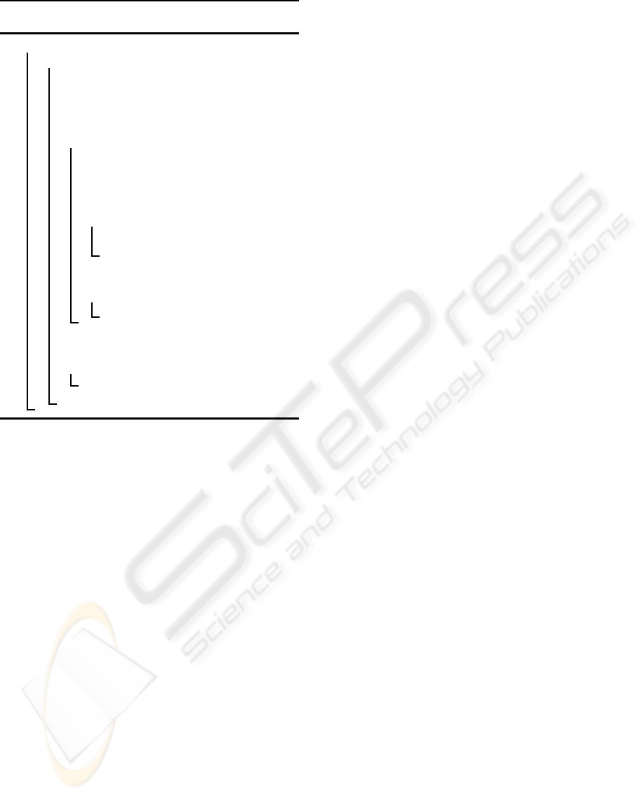
4.3 Transformation Decisions
The entire transformation is organized in an incre-
mental transformation process including (interactive)
transformation decisions. Figure 3 illustrates the
coarse structure of the transformation process and
the decision tree. One path along the transformation
direction corresponds to one specific transformation
process producing one business software system us-
ing a specific software mode.
The upper level is based on an extraction of the
logical structure from the business software system
which is transformed into the modular structure in
the intermediate representation. This is the basis for
creating the coordination structure and a coordina-
tion program for the orchestration of the modules of
the distributed system. These are obtained from code
fragments from the original software system and are
converted into components which can communicate
with other components over predefined interfaces us-
ing additional component services. The actual dis-
tributed execution is administrated by a distributed
runtime system.
ICEIS 2010 - 12th International Conference on Enterprise Information Systems
196
Specification
Level
Intermediate
Represenation
Execution
Modular
StructureStructure
Modules
Logical
Program
Services
Components
Business
Software
System
Coordination
Set of
filterselect
transform transform
createcreate
include
include
FSR
Coordination
Structure
Task
dependencies
tasks
Compontents/
Modules
Distributed Parallel Distributed
System Execution System
locally parallel
Execution
Distributed
Runtime System
Parallel
Runtime Library
Distributed
Runtime System
include
include
DS+PE
DS
PE
Code
Fragments
Figure 3: Transformation decision and transformation process to generate a distributed system and a parallel execution.
The lower level is based on an interactive identi-
fication of tasks that are extracted from the modules
constructed by the upper level. Based on their data
access pattern, tasks may have dependencies that can
be captured by a task dependency graph. The creation
of tasks by other tasks may also lead to dependencies.
The actual parallel execution of a component and the
adaptation to a specific execution environment is con-
trolled by a parallel runtime library which brings the
tasks to execution. The TDE is an important part of
this runtime library.
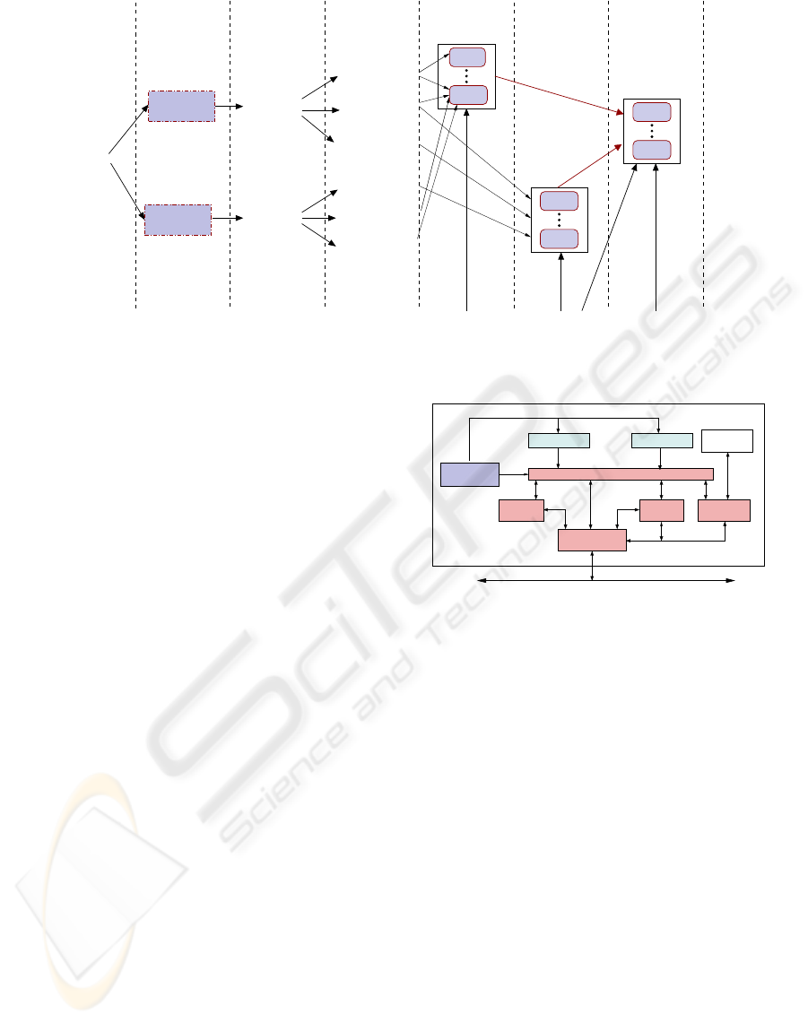
Fig. 4 gives an overview of a distributed execu-
tion of the resulting software system. The distributed
execution is controlled by a coordination component
which orchestrates the execution of the different com-
ponents on one site. At each site involved in the dis-
tribution execution, such a coordination component is
used. All data accesses of the components are per-
formed via the coordination layer which transfers the
accesses to the corresponding services provided by
the framework. Remote execution of components is
done via the communication service which can be per-
formed in different ways, including Enterprise Java
Beans (EJB). The parallel execution of one compo-
nent is hidden within the single components.
5 RELATED WORK
The transformation of software systems has been con-
sidered by many research groups. Most approaches
concentrate on the transformation into modular or
object-oriented systems or on the extraction of the
business logics. New approaches also consider dis-
tributed solutions, e.g. by providing middleware
component component
database
local
...
component
coordination
coordination layer
controls
remote access
executor
remote
communication
service
service
security consistency
service
network
access
distributed software DS
access
local
access
Figure 4: Distributed software system DS generated by the
transformation process working with a coordination com-
ponent.
solutions for data integration (Akers et al., 2004;
Menkhaus and Frei, 2004). For distributed systems,
performance aspects play an important role (Litoiu,
2004), since additional latency and transfer times may
be necessary, e.g., when replacing legacy software by
web services using protocols like SOAP (Simple Ob-
ject Access Protocol) (Brunner and Weber, 2002). For
the transformation of software systems, approaches
like DMS (Baxter et al., 2004) have been developed
and have been applied to large software systems (Ak-
ers et al., 2004). The use of automatic program trans-
formations is considered in (Akers et al., 2007).
The parallel execution of software systems on
multicore architectures using the SOA (Service-
Oriented Architecture) approach is considered in
(Isaacson, 2009). Multi-threaded programming lan-
guages with direct support for a parallel execution in-
clude Java, Cray’s Chapel, Sun’s Fortress, and IBM’s
X10. But these approaches require a re-formulation
of existing software systems, which usually requires
a re-formulation of large parts of the code.
ADAPTIVE EXECUTION OF SOFTWARE SYSTEMS ON PARALLEL MULTICORE ARCHITECTURES
197

Although there are many different approaches,
there exists no generally accepted method for the in-
cremental transformation of software systems. An
important reason for this lies in the fact that there
are many different distributed platforms like CORBA
or EJB that cannot be combined in an arbitrary way.
Therefore, a distributed realization often requires a
new implementation of the business logics.
The Model Driven Architecture (MDA) approach
(Siegel, 2005) addresses this problem and uses a
model-based approach for the step-wise generation of
distributed, component-based software. The model-
driven development od parallel software for multicore
in the area of embedded systems is considered in (Hsi-
ung, P. et al, 2009). Support for a simplification of
the transition to parallel software is collected by the
COMPASS project (Sethumadhavan et al., 2009).
6 CONCLUSIONS
The portability and efficient execution on multicore
architectures will be an important property of all soft-
ware products, including business software. In this
article, we have proposed a hybrid task-based paral-
lel programming model in which a software system is
decomposed into tasks, which may or may not be exe-
cuted in parallel to each other and additionally have an
internal multi-threadedimplementation. The software
system can exhibit a dynamic behavior such that new
tasks can be activated during the execution of another
task. The correct and efficient execution on a mul-
ticore platform is supported by a task administration
and a scheduler at application program level. Both are
integrated into a separate runtime library which sup-
ports the execution of arbitrary task-based software
systems.
In summary, we have proposed a new hybrid
parallel programming environment which is suitable
for dynamic, long-running business software sys-
tems. A software system can be newly designed for
the proposed program environment. In addition, we
have proposed a transformation mechanism to mi-
grate legacy software into the new execution model.
REFERENCES
Akers, R., Baxter, I., and Mehlich, M. (2004). Re-
Engineering C++ Components Via Automatic Pro-
gram Transformation. In Proc. of ACM Symposium on
Partial Evaluation and Program Manipulation, pages
51–55. ACM Press.
Akers, R., Baxter, I., Mehlich, M., Ellis, B., and Luecke, K.
(2007). Case study: Re-engineering c++ component
models via automatic program transformation. Inf.
Softw. Technol., 49(3):275–291.
Baxter, I., Pidgeon, C., and Mehlich, M. (2004). DMS: Pro-
gram Transformations for Practical Scalable Software
Evolution. In Proc. of the 26th Int. Conf. on Software
Engineering, pages 625–634. IEEE Press.
Brunner, R. and Weber, J. (2002). Java Web Services. Pren-
tice Hall.
Hsiung, P. et al (2009). Model-driven development of multi-
core embedded software. In IWMSE ’09: Proc. of
the 2009 ICSE Workshop on Multicore Software Engi-
neering, pages 9–16. IEEE Computer Society.
Hunold, S., Krellner, B., Rauber, T., Reichel, T., and
R¨unger, G. (2009). Pattern-based Refactoring of
Legacy Software Systems. In Proc. of the 11th
Int. Conf. on Enterprise Information Systems (ICEIS),
pages 78–89. Springer.
Isaacson, C. (2009). Software Pipelines and SOA: Releasing
the Power of Multi-Core Processing. Addison-Wesley
Professional.
Koch, G. (2005). Discovering Multi-Core:Extending the
Benefits of Moore’s Law. Intel White Paper, Technol-
ogy@Intel Magazine.
Kuck, D. (2005). Platform 2015 Software-Enabling Inno-
vation in Parallelism for the next Decade. Intel White
Paper, TechnologyIntel Magazine.
Litoiu, M. (2004). Migrating to Web Services: a perfor-
mance engineering approach. Journal of Software
Maintenance and Evolution: Research and Practice,
16:51–70.
Menkhaus, G. and Frei, U. (2004). Legacy System Integra-
tion using a Grammar-based Transformation System.
CIT - Journal of Computing and Information Technol-
ogy, 12(2):95 – 102.
Rauber, T. and R¨unger, G. (2007). Transformation of
Legacy Business Software into Client-Server Archi-
tectures. In Proc. of the 9th Int. Conf. on Enterprise
Information Systems, pages 36–43. INSTICC.
Reinders, J. (2006). Sea Change in the Software World.
Intel Software Insight, pages 3–8.
Sethumadhavan, S., Arora, N., Ganapathi, R., Demme, J.,
and Kaiser, G. (2009). COMPASS: A Community-
driven Parallelization Advisor for Sequential Soft-
ware. In Proc. of the 2009 ICSE Workshop on Mul-
ticore Software Engineering, pages 41–48. IEEE.
Siegel, J. (2005). Why use the Model Driven Architecture to
Design and Build DistributedApplications. In Proc. of
Int.Conf.Software Engineering, page 37. ACM Press.
Sutter, H. (2005). The free lunch is over – a fundamental
turn toward concurrency in software. Dr.Dobb’s Jour-
nal, 30(3).
Sutter, H. and Larus, J. (2005). Software and the Concur-
rency Revolution. ACM Queue, 3(7):54–62.
ICEIS 2010 - 12th International Conference on Enterprise Information Systems
198
