
SPECIFICATION AND INSTANTIATION OF DOMAIN SPECIFIC
PATTERNS BASED ON UML
Saoussen Rekhis Boubaker, Nadia Bouassida and Rafik Bouaziz
MIRACL-ISIMS, Sfax University, BP 1030, 3018 Sfax, Tunisia
Keywords: UML Notation, Domain-specific Patterns, Pattern Specification, Pattern Instantiation.
Abstract: Domain-specific design patterns provide for architecture reuse of reoccurring design problems in a specific
software domain. They capture domain knowledge and design expertise needed for developing applications.
Moreover, they accelerate software development since the design of a new application consists in adapting
existing patterns, instead of modeling one from the beginning. However, some problems slow their
expansion because they have to incorporate flexibility and variability in order to be instantiated for various
applications in the domain.
This paper proposes new UML notations that better represent the domain-specific design patterns. These
notations express variability of patterns to facilitate their comprehension and guide their reuse. The UML
extensions are, then, illustrated in the process control system context using an example of an acquisition
data pattern.
1 INTRODUCTION
Reusable design patterns can be classified as general
or domain-specific. General patterns (Gamma et al.,
1994) support horizontal reuse, that is, they can be
used in a variety of application domains. Due to the
fact that general patterns are too abstract, their use
can result in systems that do not correspond to
reality. Moreover, their instantiation remains a
difficult task since it is hard to determine in which
context or in which part of the system the patterns
can be used (Port, 1998). On the other hand, a
domain-specific design pattern captures particular
software domain knowledge, and thus supports
vertical reuse. It offers a flexible architecture with
clear boundaries, in terms of well-defined and highly
encapsulated parts that are in alignment with the
natural constraints of the domain (Port, 1998).
In fact, while horizontal reuse is widely spread,
Prieto-Diaz (Prieto-Diaz, 1993) states that vertical
reuse which benefits from a high quality domain
experience can result in more significant
improvement in the development cycle-time and
better software quality.
However, domain-specific patterns suffer from
representation problems since they have to express
certain concepts specific to patterns such as their
flexibility and their reuse traceability, which can not
expressed with UML. These reasons motivated
several works on domain-specific patterns
representation (Kim et al., 2004) (Montero et al.,
2005) (Couturier, 2005) (Díaz et al., 2008). They
propose new notations based on UML to facilitate
patterns specification. However, none of them
distinguishes between the extensions used in pattern
instantiation from those used in pattern specification,
which reduces their expressivity. Moreover, these
notations lack clarity since they do not focus on the
identification of the elements, the structure and the
roles played by the elements of a pattern. In
addition, they do not guide the user when adapting a
pattern to a specific application since they do not
identify the elements that may differ from one
pattern instantiation to another.
This paper proposes new UML extensions for
domain-specific design patterns. It has two-fold
objectives. Our first objective is to cope with the
representation of patterns at the specification level.
At this level, our design language offers the
following advantages: (i) it is expressive since it
facilitates the comprehension of design patterns
instantiation and guides a designer in deriving a
particular application, (ii) it shows variability since
it differentiates the fixed parts from the optional and
variable parts in the pattern (iii) it allows domain
related constraints definition.
230
Rekhis Boubaker S., Bouassida N. and Bouaziz R. (2010).
SPECIFICATION AND INSTANTIATION OF DOMAIN SPECIFIC PATTERNS BASED ON UML.
In Proceedings of the 12th International Conference on Enterprise Information Systems - Information Systems Analysis and Specification, pages
230-235
DOI: 10.5220/0002904002300235
Copyright
c
SciTePress

Our second objective is patterns expression at the
instantiation level. In fact, when several patterns are
instantiated to design an application, our profile
identifies clearly the elements belonging to each
design pattern in order to ensure the traceability.
Moreover, it avoids ambiguity when composing
patterns by showing the role played by each pattern
element.
The remainder of this paper is organized as
follows. Section 2 overviews currently proposed
design languages and their extensions. Section 3
presents our proposition to represent an UML profile
for domain specific design patterns. Section 4
illustrates the design language through the definition
of the acquisition data pattern for the process control
system. Section 5 concludes the paper and outlines
future work.
2 RELATED WORK
Design patterns have mostly been described using
natural language, complex mathematical or logic
based formalisms (Eden et al., 1999) (Mikkonen,
1998) which are not easily understood by an
inexperienced designer. This leads to complications
in incorporating design patterns effectively into the
modelling of a new system. To remediate to this
difficulty, the solution is using an expressive visual
notation based on UML to specify patterns. This
improves the pattern specification quality because
UML allows to easily visualise, define and
document the artefacts of the system under
development.
Several works for pattern representation based on
UML have been proposed.
Kim et al., (Kim et al., 2004) propose a Role
Based Modeling Language (RBML). This language
is interested only on representing patterns at the
specification level. It specifies patterns using a
structure of roles. Each role is associated with a
UML metaclass that is called its base. The properties
expressed in a role define a subset of the base
metaclass instances. For example, a role whose base
is the Classifier metaclass expresses properties that
define a subset of UML classifiers (instances of
Classifier). Properties in a classifier role can be
expressed in structural feature roles or behavioral
feature roles specifying respectively the attributes
and operations of conforming classifiers.
This approach treats domain patterns as
templates where the parameters are roles. The
constraint templates are used to specify semantic
properties associated with features that conform to
structural and behavioral feature roles. The RBML
defines well the properties that must be instantiated
by each application in the pattern domain, but it does
not focus on expressing variability. Moreover,
RBML does not offer mechanisms for patterns
composition in a domain.
Unlike the previous work, the UML profile
proposed by Arnaud (Arnaud et al., 2007) focuses
on the variability expression in the functional,
dynamic and static views. The functional model
fragment (use case diagram) is the entrance point for
the instantiation process, where the application
designer selects a functionality variant. However,
the use case diagram is too abstract and can not be
used as an input model for the patterns instantiation.
In fact, the use case diagram is at a high level of
abstraction and thus the designer cannot identify, for
example, the optional attributes or methods
according to its needs. Thereby, this profile is not
very expressive and it makes the patterns
composition more difficult since the static view of a
pattern is decomposed into very elementary
separated packages which contain one or two
classes. Each package is relative to one use case of
the functional diagram.
Overall, currently proposed UML based design
languages for patterns are more interested in the
patterns specification level than in the instantiation
one. Moreover, they do not express variability nor
composition aspects. Thus, they do not offer an
expressive notation guiding the designer in pattern
instantiation.
3 DOMAIN-SPECIFIC DESIGN
PATTERNS PROFILE
In the present work, we offer UML extensions
(OMG (b), 2007) distinguishing between domain-
specific design patterns representation at the
specification and instantiation levels. At the
specification level, our profile facilitates the pattern
instantiation through the expression of pattern
variability and the definition of the constraints to be
fulfilled when the designer adapts the patterns
according to its needs. At the instantiation level, our
profile offers extensions for comprehension,
traceability and composition purposes through the
identification of the roles played by each pattern
element in the application instantiating it.
In the following, we present some UML 2.1.2
(OMG, 2007) basic concepts expressing the
variability in the static and behavioral views. Then,
SPECIFICATION AND INSTANTIATION OF DOMAIN SPECIFIC PATTERNS BASED ON UML
231

we show our UML extensions to represent domain-
specific design patterns.
In the class diagram, the generalization
relationship represents variation points which are
defined by an abstract class and a set of subclasses
that constitute the different variants. At least, one of
these subclasses is chosen in a pattern instantiation.
There are two types of UML constraints that can be
applied on the generalization relation:
- {incomplete}: this constraint indicates that the
design provides only a sample of subclasses and
that the user may add other subclasses in an
instantiation.
- {xor}: this constraint indicates that the designer
must choose one and only one variant among the
presented subclasses during the instantiation.
In addition, the interface concept allows to express
variability since the designer can choose a particular
interface realization among the various possibilities.
In the sequence diagram, an interaction sequence
can be grouped into an entity, called combined
fragment. This latter defines a set of interaction
operators, particularly (alt: alternative) and (opt:
optional) operators. The interaction operator (alt)
indicates that a set of interactions are alternative. It
is used with an associated guard that informs the
user that only one set of interactions will be chosen.
While the interaction operator (opt) indicates that a
set of interactions represents an optional behavior
that can be omitted in a model instance.
Domain-specific design pattern are generic
designs intended to be specialized and reused by an
application. For this reason, in addition to the UML
variability concepts, we need new notations
distinguishing the commonalities and differences
between applications in the pattern domain.
Moreover, we need new concepts for the explicit
representation of the pattern elements roles in order
to trace back to the design pattern from a complex
design diagram.
In the next section, we describe the extensions
that we propose to take into account these new
concepts.
3.1 Extensions for Specifying Design
Patterns
In this section, we propose new stereotypes showing
the optional and fundamental elements participating
in a pattern and assisting the designer in pattern
reuse. Thus, the class diagram Metamodel is
extended with the following stereotypes:
• Stereotype <<optional>> (applied to the Feature
UML Metaclass): This stereotype is used to specify
optional features in UML class diagram. When an
attribute (or method) is stereotyped optional, then it
can be omitted in a pattern instance.
Each method or attribute which is not stereotyped
<<optional>> means that it is an essential element
that plays an important role in the pattern.
• Stereotype <<mandatory>> (applied to the UML
Metaclasses: Class, Association, Interface, Lifeline
and ClassAssociation): This stereotype is used to
specify a fundamental class or relation (association,
aggregation,…) that must have at least one instance
in a specific application model. A fundamental
element in the pattern is drawn with a highlighted
line like this class .
Each relation or class which is not highlighted
means that it is an optional element, except the
generalization relation that permits to represent
variant elements.
• Stereotype <<extensible>> (applied to the UML
Metaclasses: Class, Interface and ClassAssociation):
This stereotype is inspired from {extensible} tagged
value proposed in (Bouassida et al., 2006). It
indicates that the class interface may be extended by
adding new attributes and/or methods. Moreover,
two properties related to the extensible stereotype
are proposed, in order to specify the type of features
(attribute or method) that may be added by the
designer.
- Extensible Attribute tag: It takes the value false,
to indicate that the designer cannot add new
attributes when he instantiates the pattern.
Otherwise, this tag takes the value true.
- Extensible Method tag: It indicates if the designer
may add new methods when he instantiates the
pattern. The default value is true.
• Stereotype <<variable>> (applied to the
Operation UML Metaclass): This stereotype has the
same meaning with the {variable} tagged value
proposed in (Bouassida et al., 2006). It indicates that
the method implementation varies according to the
pattern instantiation.
Note that the designer can add constraints describing
properties inherent to the pattern domain. These
constraints are expressed in OCL (Object Constraint
Language) (OMG (a), 2003).
3.2 Extensions for Instantiating Design
Patterns
Some of the existing notations, such as a UML
profile (Dong & Yang, 2003), provide support on
ICEIS 2010 - 12th International Conference on Enterprise Information Systems
232
how to keep trace of the pattern when instantiated.
These notations focus only on generic design
patterns for which it is difficult to recognize the
pattern instance when it is composed with others in a
particular design. Thus, it is essential to hold the
pattern name and the role played by each element
(class, attribute and method) in the instantiation.
However, a domain specific pattern is
instantiated in the scope of a domain. Therefore, it is
easy to retrieve the pattern-related information even
after the pattern is applied or composed with other
patterns. We assume that omitting both the name and
the role of pattern attributes and operations will not
create any ambiguity. For this reason, we propose to
present only the pattern name and the roles of the
classes in order to avoid having overloaded models.
In fact, pattern-related information should be
minimized in the class and sequence diagrams for
readability.
We propose to define two new stereotypes for
the explicit visualization of patterns in an application
design:
• <<Pattern Class>> stereotype: It is applied to the
Class UML metaclass in order to indicate that it is
an instantiated pattern class and not originally
defined by the designer. Two properties, relative to
this stereotype, are defined:
- patternName tag : indicates the pattern name,
- participantRole tag : indicates the role played by
the class in a pattern instance.
This stereotype allows to eliminate any confusion
when patterns are composed. That is, when two or
more classes represent the overlapping part of the
composition, the proposed stereotype shows the
roles that these classes play in each pattern.
• <<Pattern Lifeline>> stereotype: It is applied to
the Lifeline metaclass in order to distinguish
between the objects instantiated from the pattern
sequence diagram and those defined by the designer.
This stereotype has the same properties than
<<patternClass>> stereotype.
4 CASE STUDY
To illustrate our profile, we have chosen the process
control systems domain. In fact, applications in this
domain monitor and control the values of certain
variables through a set of components that work
together to achieve a common objective or purpose
(Reinhartz-Berger et al., 2009). Application areas
within this domain include engineering and
industrial control systems, financial derivation-
tracking products, and so on. They perform several
processes among which: the data acquisition and the
data control processes. We focus in this paper on
representing a pattern for the data acquisition
process using our UML profile. Then, at the
instantiation level, the pattern is reused through an
example of an industrial control application. Due to
space limitation, only the extensions to the UML
class diagram are illustrated.
4.1 Pattern Specification
The variety within the process control system
domain is quite large. Applications in the domain
defer in the number of the observed elements, the
number and type of controlled values and sensors,
whether the history of measurements is recorded or
not, etc (Reinhartz-Berger et al., 2009).
Nevertheless, all applications in the process control
domain should define at least one sensor to acquire
data from the environment. A sensor is defined as a
device that measures or detects a physical
phenomenon. This detected measure is usable for
command ends. The sensors can be classified
according to their functioning principle. Some
applications use passive sensors and others use
active sensors.
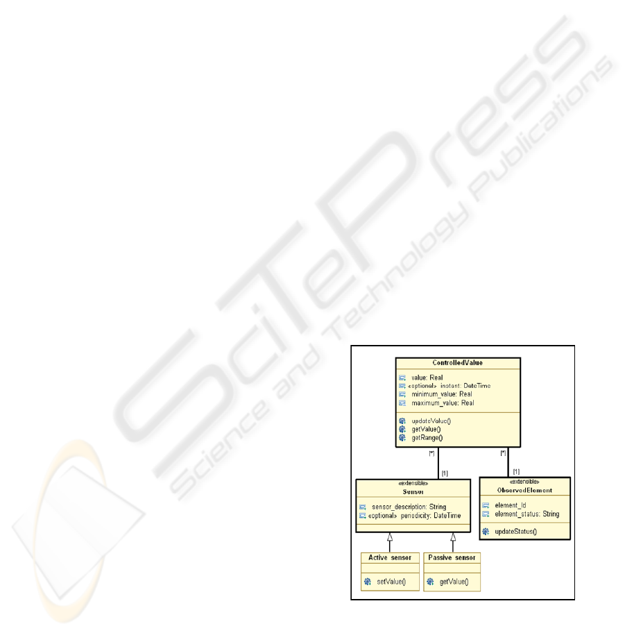
Figure 1 represents the data acquisition pattern at
the specification level. As indicated in this figure,
the different types of sensors present variants for the
sensor abstract class.
Figure 1: Specification of the data acquisition pattern.
An active sensor takes the transmission initiative of
its current value (push mechanism).
It must be able
to transmit a signal setValue to one object or to a
group of objects in order to update the value of a
SPECIFICATION AND INSTANTIATION OF DOMAIN SPECIFIC PATTERNS BASED ON UML
233
measure. While a passive sensor, it can transmit its
value only on demand of an operator (pull
mechanism). It must have a method getValue to read
the current value.
In addition, a process control application should
have at least one observed element and at least one
ControlledValue class. An ObservedElement class
represents the description of a physical element that
is supervised by one or more sensors. It has an
identity and status attributes specifying the evolution
of its status according to the variation of the
controlled values. Thus, the ControlledValue class
has an attribute named Value containing the final
value captured by the related updateValue ()
method, two attributes specifying its range
constraints and at least one operation for getting
these ranges. The range constraints define the
minimum and the maximum values for which the
system does not detect an anomaly. The
ControlledValue class has also an optional attribute
named Instant containing the last time at which the
value was produced.
4.2 Pattern Instantiation: An Example
The purpose of the water level control of an
industrial regulation system is to monitor and control
the water levels in tanks, ensuring that the actual
water level of tank
i
is always in the closed range
[Low-level, High-level] (Reinhartz-Berger et al.,
2009). If a problem occurs and some of the tanks do
not satisfy their boundary constraints, the system
tries to resolve the problem internally, for example,
by rebooting the system. However, if the problem
cannot be resolved internally, the system requires a
special treatment of an external exception handler.
The actual levels of the different tanks are
measured by boundary sticks sensors. Each acquired
measure is characterized by a value, a minimum
value and a maximum value of the desired water
level in the tank. When the water height in the tank
reaches its low (or high) desirable limit, the filling
(or emptying) faucet is activated to inject water into
the tank (or to drain water from the tank).
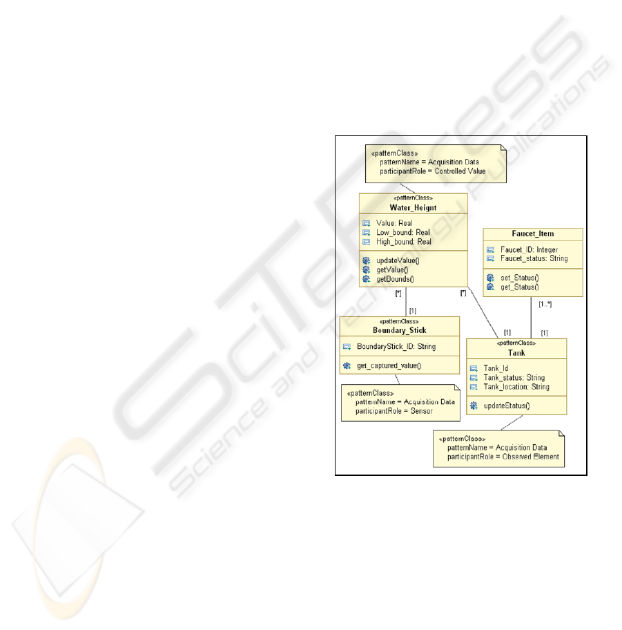
Figure 2 illustrates the data acquisition process
of the water level control application. The design of
this application is facilitated by the reuse of the
pattern specification example. In fact, the designer
instantiates first the elements that play a significant
role in the data acquisition pattern (drawn with a
highlight line in Figure 1) and substitutes them by
specific elements adapted to the context of the water
level control application. This application controls
one type of elements (tanks) and monitors one type
of controlled value, which is the water height in
tanks, through the boundary sticks passive sensors.
The passive sensor variant is chosen because all
sensors used in this application can not publish their
values spontaneously.
After that, the optional elements are identified in
order to determine those that can be omitted. For
example, the instant optional attribute is omitted
since the time of the measured water heights is not
recorded in this application.
Moreover, the pattern name and its role are
indicated by using respectively the tagged values
patternName and participantRole of the stereotype
<<patternClass>>. For example, the instantiated
class Tank plays the role of an ObservedElement in
the data acquisition pattern. Thus, the patternName
tag value is AcquisitionData and the participantRole
tag value is Observed Element.
Figure 2: Example of data acquisition pattern instantiation.
Finally, specific elements related to the designed
application are added. New attributes (or methods)
can be added only for the pattern classes stereotyped
<<extensible>> and tagged with extensibleAttribute
(or extensible-Method). Notice that in the water
level control application, a Location attribute
characterizing the Tank class is added since the
corresponding ObservedElement class in the pattern
is declared extensible. In addition, the class
Faucet_item is added. This class is characterized by
the faucet-ID attribute and faucet-Status attribute
indicating if a faucet is opened or closed.
ICEIS 2010 - 12th International Conference on Enterprise Information Systems
234

5 CONCLUSIONS
This paper presented a UML profile for domain-
specific design patterns. The proposed extensions
allow distinguishing clearly between the different
parts constituting the pattern in order to guide the
designer in determining the variable elements that
may differ from one application to another. It allows
also to identify, easily, design patterns when they are
applied to model a particular application in the
pattern domain. The paper illustrated the proposed
profile through the data acquisition pattern for the
process control system domain.
Our future works include the definition of a
process for the creation and specification of domain-
specific design patterns through the unification of
the existing applications in the domain. This allows
to reduce the costs of domain patterns engineering
activities and to improve their profitability.
REFERENCES
Arnaud N., Front A.and Rieu D., Expression et usage de la
variabilité dans les patrons de conception, Revue des
sciences et technologies de l'information, série :
Ingénierie des Systèmes d'Information, vol. 12/4, pp.
21-24, 2007.
Bouassida N., Ben-Abdallah H., Extending UML to guide
design pattern reuse, Sixth Arab International
Conference On Computer Science Applications,
Dubai, 2006.
Díaz P., Aedo I., Beth Rosson M., Visual representation of
web design patterns for end-users, Proceedings of the
working conference on Advanced visual interfaces,
pages 408-411, 2008.
Couturier V., Pattern analysis for the cooperative
information system engineering, Revue Lavoisier,
ISSN 1262-1137, vol. 11, no 4, pages 141-175, 2005.
Dong J. and Yang S., Visualizing design patterns with a
UML profile, proceedings of IEEE Symposium on
Human Centric Computing Languages and
Environments, pp: 123-125, 2003.
Eden A.H., Gil J., Hirshfeld Y., Yehudai A., Towards a
mathematical foundation for design patterns,
Technical report, dept.of information technology,
U.Uppsala, 1999.
Gamma E., Helm R., Johnson R.E, Vlissides J., Design
patterns: Elements of Reusable Object-Oriented
Software, Addison-Wesley Edition, 1994.
Kim D.K., France R., Ghosh S., A UML-based language
for specifying domain-specific patterns, Journal of
Visual Languages and Computing, 15 (2004) pp. 265–
289, 2004.
Mikkonen T., Formalizing Design Patterns, Proc. 20th
International Conference on Software Engineering—
ICSE, pp. 115–124, 1998.
Montero S., Díaz P., Aedo I.,
A Semantic Representation
for Domain-Specific Patterns, Springer-Verlag Berlin
Heidelberg, vol 3511, pages 129-140, 2005.
OMG (a), UML 2.0 OCL specification, 2003
OMG (b), Unified Modeling Language (UML)
Infrastructure: v2.1.2, formal/2007-11-04, 2007.
Port D., Derivation of Domain Specific Design Patterns.
USC Center for software engineering, 1998.
Prieto-Diaz R., Status report: software reusability, IEEE
Software 10 (3) pp. 61–66, 1993.
Reinhartz-Berger I., Sturm A., Utilizing domain models
for application design and validation, Information and
Software Technology, vol 51, pages 1275-1289, 2009.
Yacoub S. M., Ammar H., Pattern-Oriented Analysis and
Design: Composing Patterns to Design Software
Systems, Published by Addison-Wesley Professional,
August 2003.
SPECIFICATION AND INSTANTIATION OF DOMAIN SPECIFIC PATTERNS BASED ON UML
235
