
A PLATFORM DEDICATED TO SHARE AND MUTUALIZE
ENVIRONMENTAL APPLICATIONS
Th
´
er
`
ese Libourel, Yuan Lin, Isabelle Mougenot, Christelle Pierkot
Universit
´
e Montpellier 2, LIRMM, 161 rue Ada, 34095 Montpellier Cedex, France
Jean Christophe Desconnets
Maison de la t
´
el
´
ed
´
etection, 500, avenue J. F. Breton, 34093 Montpellier cedex 5, France
Keywords:
Platform MDWeb, Meta description, Scientific workflow, Infrastructure, Conformity checking.
Abstract:
Scientists of the environmental domains (biology, geographical information, etc.) need to capitalize, distribute
and validate their scientific experiments of varying complexities. A multi-function platform will be an adapt-
able candidate for replying this request. After a short introduction of our context and objective, this article
presents the project MDWeb, a platform that we have conceived and realized for sharing and mutualizing
geographic data. Based on this platform, our main interest is actually focused on providing users a workflow
environment, which will be integrated soon after in this platform as a functional component. An introduction
to a three-level workflow environment architecture (static, intermediate, dynamic) is presented. In this article,
we focus mainly on the ”static” level, which concerns the first phase of constructing a business process chain,
and a discussion around the ”intermediate” level, which covers both the instantiation of a business process
chain and the validation, in terms of conformity, of the generated chain.
1 INTRODUCTION
1.1 General
Environmental applications (biodiversity, ecology,
agronomy, etc.) are undergoing considerable growth,
requiring the establishment of hardware and software
infrastructures. Indeed, communities want to benefit
from efficient mutualization frameworks because data
and processes already exist in quantity. Data associ-
ated with scientific experiments is often voluminous
and complex to acquire and the processes that deal
with it change over time. The experiments themselves
are rarely simple and most often correspond to a more
or less sophisticated organization of processes.
In this context, for conceiving and realizing infras-
tructures for sharing and mutualization ((Barde et al.,
2005; Desconnets et al., 2007)) raises several chal-
lenges :
• The syntactic interoperability relative to various
data and treatments, which requires good knowl-
edge of those available data and treatments in the
domain. The initiative normalizers propose to turn
to the metadata norms and standards.
• The semantic interoperability relative to the do-
main knowledge, which is much more compli-
cated. In general, communities co-construct a
shard vocabulary (thesaurus or a domain ontol-
ogy) to fill this gap.
• The compatibility and the substitutability of treat-
ments in an experimental process chain. We need
a formal language for defining process chains, and
then, a thorough reflection of its realization.
1.2 Objective
Our objective is thus to construct a platform for shar-
ing and mutualization of existing data and processes.
This platform must be developed according to stan-
dards to ensure semantic and syntactic interoperabil-
ity. An overview of which is shown in figure 1.
It provides users with a graphical interface and
several functional components:
• Metadata manager for referencing data and pro-
cesses (using descriptions of type metadata),
1
1
Catalog M
3
Cat : www.intelec.ca/html/fr/technologies/
m3cat.html
50
Libourel T., Lin Y., Mougenot I., Pierkot C. and Christophe Desconnets J. (2010).
A PLATFORM DEDICATED TO SHARE AND MUTUALIZE ENVIRONMENTAL APPLICATIONS.
In Proceedings of the 12th International Conference on Enterprise Information Systems - Databases and Information Systems Integration, pages 50-57
DOI: 10.5220/0002904500500057
Copyright
c
SciTePress
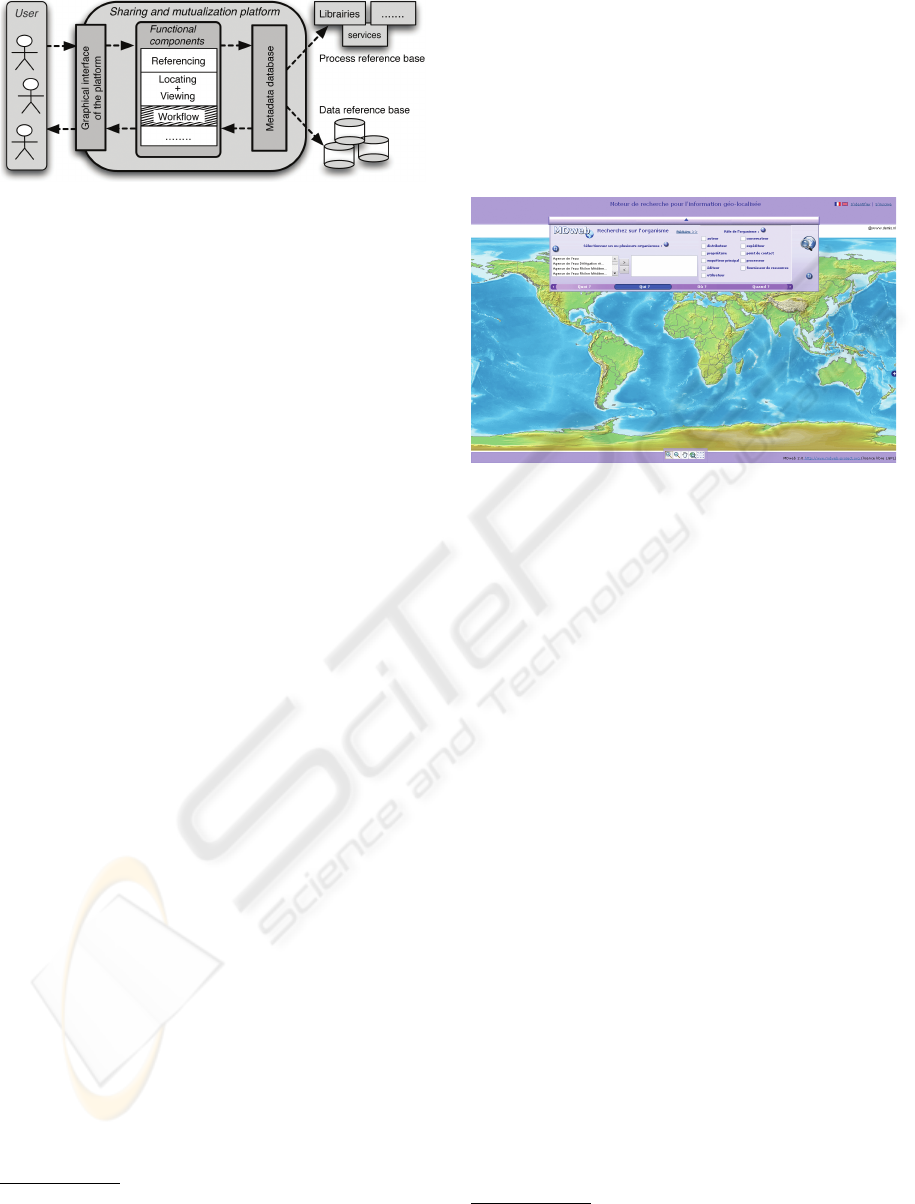
Figure 1: Overview of the sharing and mutualization plat-
form.
• Search engine for locating and viewing resources
(data/processes) using the above-mentioned de-
scriptions, both for local and remote resources,
2
• Workflow experimentation environment.
The two first components are now operationals
and have been implemented in the MDWeb Project
3
(Desconnets, 2007). The component of a workflow
environment for the definition, instantiation and
execution of experimental process chains is now our
research subject.
In the following of this article, we first present in
the section 2 an overview of the MDWeb project, a
platform for sharing and mutualizing geographic re-
source, and it’s main constituents. In the section 3, we
introduce firstly our general vision of a workflow en-
vironment, and then, our main contributions concern-
ing a simple workflow definition language and the re-
flections about the conformity problem in a workflow
chain will be presented in the two following sub sec-
tions 3.1 and 3.2. Finally, the last section presents
perspectives and conclusions.
2 MDWEB
Platform MDWeb is an operational free tool, used by
several national and international institutions for cat-
alogating and locating environmental resources over
the web. It is based on current geographic information
metadata (ISO 19115) and communication (OGCs
CSW-2) standards and conforms to the rules for im-
plementing metadata and the associated discovery
services of the INSPIRE directives (INPIRE, 2008;
ISO19115, 2006; OGC, 2007). MDWeb allows users
to reference spatial datasets thanks to metadata, and
then publish and made them available. On the other
hand, users can also search and visualize datasets via
2
Search engine GeoNetwork: http://geonetwork-open
source.org
3
http://mdweb.codehaus.org/
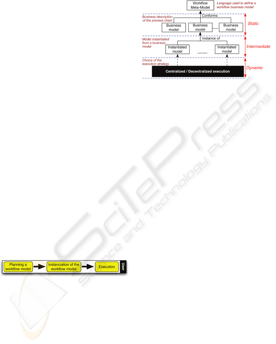
a multi criteria research. Figure 2 shows an overview
of this platform.
One of the MDWeb originalities is thus to include
the spatial and semantic aspects in the description
of the resource. This is achieved by using thematic
repositories (thesauri) and spatial repositories (geo-
graphic objects of interest) specific to the target ap-
plication.
Figure 2: Overview of the MDWeb Tool
2.1 Thesaurus
In the project MDWeb, we integrated thesaurus (a
controlled vocabulary bringing a set of terms rep-
resenting the concepts of a particular area) in order
to facilitate metadata search and record, because the
terms of a thesaurus can be used to index documents.
Further more, a specific thesaurus to the application
can be defined or reference thesaurus (like GEMET
4
, or AGROVOC
5
) can be imported into the service
MDweb.
2.2 Metadata
ISO 19115 (ISO19115, 2006), the metadata standard
for geographic information, allows a specific commu-
nity to use profile for determining the set of metadata
they need. An overview of this standard can be found
in (Pierkot, 2008).
MDWeb allows, through the concept of metadata
profile, select and specify properties of metadata ele-
ments that will be used for documenting a resource.
Nine profiles corresponding to different data types
(data collection or data set) are proposed in MDWeb.
One more profile for describing the treatments is ac-
tually under construction.
A metadata editor offers the possibility to enter
a new sheet by selecting the desired profiles, a new
form will be created for entering the metadata.
4
http://www.eionet.europa.eu/gemet/about?langcode=en
5
http://aims.fao.org/website/AGROVOC-Thesaurus
A PLATFORM DEDICATED TO SHARE AND MUTUALIZE ENVIRONMENTAL APPLICATIONS
51
2.3 Search Engine
The metadata search engine in MDWeb provides
users various research modes, one of the most use-
ful is the ”multiple-criteria searches”, which allows
to compose a query based on four criterias :
• What: Allows the user to specify one or more
keywords.
• When: Allows the user to specify the period in
which the reference was created.
• Where: Allows the user to restrict the search to a
specific geographical location of data.
• Who: Allows the user to specify an administra-
tive entity (agency, institution, etc.) of data.
2.4 Summary
The MDWeb project focused on sharing and mutual-
izing existing data, we disposed, as presented in this
section, a component for managing metadata and a
search engine for localizing data based on these meta
informations. In short term, we will also extend the
same functionality for the treatments. The next im-
portant step for us, is to focus on the workflow com-
ponent, as introduced in the section 1.2.
3 OUR VISION OF A
WORKFLOW ENVIRONMENT
Our objective is to integrate the workflow environ-
ment in the sharing and mutualization platform. From
the business point of view (experimenters), workflow
usage corresponds to the three stages shown in figure
3):
Figure 3: Business point of view.
1. Definition: abstract definition of a process chain
corresponding to an experimentation (planning of
experiments),
2. Instantiation: more specific definition after
identifying the various elements of the chain
(data/processes),
3. Execution: customized execution (according to
strategies corresponding to the requirements).
It is from this experimental life cycle and inspired
by architectural styles proposed by OMG (OMG,
2006) that we have proposed the 3-level architecture
(cf. fig. 4):
Figure 4: A workflow environment.
1. The static level concerns the design phase and
consists of constructing business process models
(abstract) using a simple language defined by a
meta level. There exists several standards and
specifications for defining a process model. In
(Lin et al., 2009), we have analysed some of them
like : UML (Activity diagram) (OMG, 2001),
SPEM (OMG, 2005), BPMN (OMG, 0082). One
common point of these standards and specifica-
tions is that, they are all very comprehensive but
require substantial time to understand and to use,
in order to take full advantage of them. However,
it might be not so easy for scientists which are not
experts in this field.
2. The intermediate level represents an instantiation
and pre-control phase. Before going on to the
execution phase, the users should refine and cus-
tomize their experimentation based on the busi-
ness process model defined during the last step,
by determining and localizing the most suitable
sources of data, programs and services. After
that, we propose to include pre-control within this
phase, for guaranteeing the executability of the
generated process chain. The objective of this pre-
control is to verify the validity of the instanced
chain based on formal conformity rules. We then
continued our studies by analysing the different
scientific workflow environments like Kepler (Al-
tintas et al., 2006), Taverna-myGrid (Hull et al.,
2006), BioSide (BioSide, 2008), etc. Each project
declines an graphical interface for defining work-
flow (using a abstract syntax not necessarily ac-
cessible for users), and then, during the execu-
tion of a defined workflow, they handle the confor-
mity problem by using specific adaptations, either
manually or semi-automatically.
3. The dynamic level concerns the actual execu-
tion phase. This takes place according to various
strategies defined by both the experimenter and
the operational configurations.
ICEIS 2010 - 12th International Conference on Enterprise Information Systems
52
In this article, we will only cover the advances re-
lating to the first two levels : ”static” and ”interme-
diate”. Our contributions concerning these two lev-
els are presented in the following sub-sections : A
meta-model corresponding to the abstract syntax of
a simplified but complete workflow description lan-
guage ; An analysis of the different situations of com-
patibility in a process chain, which has been realized
from a workflow model conforms to the meta-model.
A original proposal for conformity checking is pre-
sented and discussed at the end.
3.1 Static Level: Language for Defining
Process Chains
As analysed in the last section, for the static level, we
have to propose a language to define process chains.
It should be as simple as possible since the user com-
munity does not consist of computer experts. Never-
theless, the language should be as comprehensive as
possible to be able to best represent the experiments.
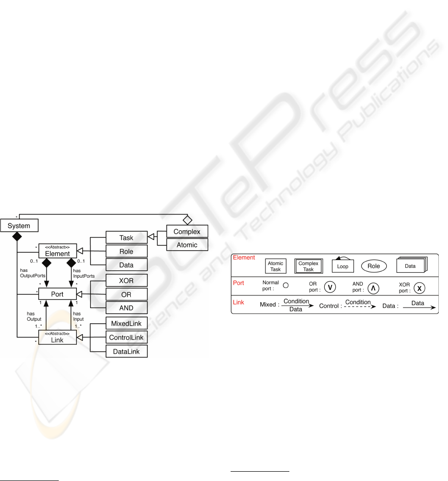
Our language is defined by a meta-model (cf. fig
5) which is inspired by the existing meta-models that
we have analyzed and by the general meta-model re-
lating to graphs and ontologies. The goal is to de-
fine the minimum number of necessary elements to
be able to represent the maximum number of possible
situations (F
¨
urst., 2002).
Figure 5: The workflow meta-model.
The meta-model was designed from the point of
view of the workflow software environment. It is thus
perceived, at the most abstract level, as consisting of
(elements) and (links) between elements. The connec-
tion between elements and links is provided by the
concept of the port.
The elements can be divided into:
• Tasks: predefined tasks, to use or reuse
6
,
6
In the current context, Web services can, for example,
be considered tasks.
• Roles: existing roles (which will intervene during
the execution phase),
• Data: available resources, to be mobilized.
The concept of the task corresponds to concepts of
Activity, Process, etc. as generally used in the other
workflow meta-models. We further break up this con-
cept with a composite template: a task can be complex
or atomic, with the possibility of reusing a complex
task concatenated into an atomic task.
The elements are connected by unidirectional
links
7
via ports. We distinguish between:
• The data links (DataLink) which are used, on the
one hand, to transfer data between elements and,
on the other, to ensure the correct sequence of the
processes.
• The control links (ControlLink) and mixed links
(MixedLink) which are included mainly to control
the authorization of execution and/or the temporal
scheduling.
Links connect elements by way of ports (normal
ports, by default) which are attached to them. Each
element has input/output ports (the I/O type is con-
nected in the direction of the corresponding link).
In addition, to be able to handle more complex ex-
amples such as data merging, synchronization, etc., of
the elements (port and link), specific ports are intro-
duced: AND, OR, and XOR.
To facilitate the manipulation of processes, a cor-
responding graphical language is proposed, cf. fig 6.
Figure 6: An associated graphical language.
3.2 Intermediate Level: Concept of
Context and Conformity
At the intermediate level, the user transforms the ab-
stract business model into an instantiated concrete
model using appropriate data and processes. (To do
this, he will use the platform’s search engine compo-
nent and the meta-information on the resource.) We
propose to verify and validate the concrete model be-
fore proceeding to its execution. Towards this end,
7
There is no direct link between role and resource. In
most cases, links between role and resource can be deduced
from role-task and task-resource links.
A PLATFORM DEDICATED TO SHARE AND MUTUALIZE ENVIRONMENTAL APPLICATIONS
53
we present the sub-stages planned for the intermedi-
ate level, the difficulties that arise and the solutions
we propose.
3.3 Analysis of the ”Intermediate”
Level’s Sub-stages
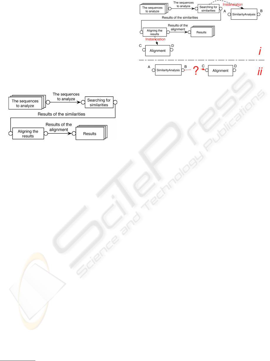
To illustrate the different stages, we use an example
from the biological domain. Figure 7 shows the ab-
stract business model: it starts by an analysis of sim-
ilarities based on a set of supplied sequences, then
the results are transferred to another process to align
them.
Figure 7: A business model of the biological domain.
To us, the two essential sub-stages during the ”in-
termediate” phase are:
1. Instantiation Stage. It consists of replacing the
abstract elements defined in the business model by
real resources which are found and located with
the help of the platform’s search engine. This
search is based on the meta-information of the real
resources (stored in the local base or in directo-
ries).
Considering again the example of figure 7, sup-
pose that the search leads to two concrete in-
stances for the two abstract processes: T1 and T2,
whose signatures are:
• T1: SimilarityAnalysis (A): B. T1 takes data
of format
8
A as input and returns a result of
format B
• T2: Alignment (C): D. T2 takes data of format
C as input and returns a result of format D
After instantiation of the business model, we ar-
rive at the situation in figure 8-i.
2. Chaining and Validation Stage. Concrete ele-
ments should be linked between themselves using
different predefined links of the meta-model. In
the example under consideration, it will be data
links that will be used. A further difficulty arises
(cf. fig 8-ii) which we call ”conformity”: does
the data exchanged between the two concrete pro-
cesses conform to these processes’ signature?
8
We use ”data type” or ”data format”
Figure 8: Instantiation from the business model.
3.3.1 Handling Conformity
Based on the preceding analyses, we can say that the
two sub-stages have objectives of:
• searching and locating the resources necessary for
instantiating the business model
• verifying and correcting the incompatibilities in
the generated instantiated model to be able to ob-
tain a valid model.
To achieve these objectives, several reflections are
conducted in parallel: the first bears on the modeling
of the different resource categories that make up the
environment or context of the information technology
platform, the second bears on the choice, depending
on the problems posed, of the formalism most suitable
for representing the knowledge associated with these
various resources.
Concept of Context or Environment of the Plat-
form. The concept of the context or the environ-
ment of the platform can be represented by the fol-
lowing three sub-organizations (cf. fig.9):
• organization of human resources: they manage
the user accounts on the platform as well as their
different roles and associated access rights,
• organization of data, and
• organization of processes.
Since we started with the hypothesis of delocal-
ized resources (data and processes), we propose to
store only their references locally, in the form of ap-
propriate descriptions. These descriptions (metadata
of some sort) are arranged in order within specializa-
tion/generalization hierarchies. The latter serve as a
basis for the localization and search of real resources.
As shown in the class diagram of the global ar-
chitecture (cf. fig9), in the organization of data hier-
archy, a description relating to some concrete data is
linked to the corresponding data format. And in the
ICEIS 2010 - 12th International Conference on Enterprise Information Systems
54
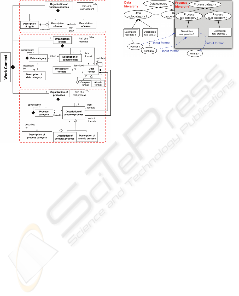
Figure 9: Concept of work context.
organization of processes hierarchy, the description
relating to a concrete process comprises at the mini-
mum the process’s signature, which itself includes the
input and output data formats.
For the construction of these hierarchies, we are
actually developing a formalism which conforms the
metadata profile defined in the project MDWeb.
Proposed Solution for Verifying Conformity. For
the purpose of verifying conformity, we propose to
use the context defined earlier.
Let us take an example: we have a data hierarchy
and a processes hierarchy (left and right parts, respec-
tively, in figure 10). The manner of establishing rela-
tionships between these two hierarchies is essentially
based on the matching between different predefined
data formats and the process signatures.
In general, we intend to construct the global re-
source graph after analyzing the stored descriptions.
Definition of a Resource Graph. A resource graph in
our work context is, in fact, an oriented graph G=(N,
A), with:
• N a non-empty finite set of nodes, N = N
P
∪ N
D
∪ N
F
, with:
1. N
P
: a set of nodes, which represents concrete
processes;
2. N
D
: a set of nodes, which represents real data;
Figure 10: Matching of process signatures and of their in-
put/output data formats.
3. N
F
: a set of nodes, which represents data for-
mats.
We can then determine whether a node n∈N, then
n∈N
P
∨ n∈N
D
∨ n∈N
F
.
• A a set of arcs between the nodes. If an arc
a=(n
1
,n
2
) ∈A, then n
1
∈ N ∧ n
2
∈ N ∧ n
1
6=n
2
.
Two types of arcs are presented in a resource
graph:
1. A
R
: a set of reference arcs. If an arc a
r
=(n
1
,n
2
)
∈ A
R
,
then (n
1
∈ N
D
∧ n
2
∈ N
F
) ∨ (n
1
∈ N
P
∧ n
2
∈
N
F
) ∨ (n
1
∈ N
F
∧ n
2
∈ N
P
)
2. A
S
: a set of specialization arcs. If an arc
a
s
=(n
1
,n
2
)∈A
S
,
then n
1
∈ N
F
∧ n
2
∈ N
F
An example of a resource graph is shown in fig-
ure 11. It has been obtained by using a set of graph-
ical symbols meant to represent data descriptions
(overlaid rectangles), the various data formats (the
ovals), and the process descriptions (the rectangles
with handles, with the latter representing signatures).
The reference links (ref ) constructed between the re-
sources are in fact the relationships established from
the matching between data formats stored in each of
the descriptions (of data/process). For example, Data
1 is in format 1; Process 6 takes data in format 2 and
format 4 as input and generates results in format 5.
To not unnecessarily complicate the diagram, only a
specialization link (subType) between format 6 and
format 8 is added.
Note: For the graph to remain readable and at the
level of concrete resources, we have not shown the
concept of resource categories from figure 10.
Based on the preceding hypotheses, we think that
the problem of verification and validation of the con-
formity in an instances model can be considered as an
itinerary-finding problem between two fixed nodes of
the resource graph (cf. fig 11).
The verification of conformity thus comes down
to determining if there exists a match between two
A PLATFORM DEDICATED TO SHARE AND MUTUALIZE ENVIRONMENTAL APPLICATIONS
55
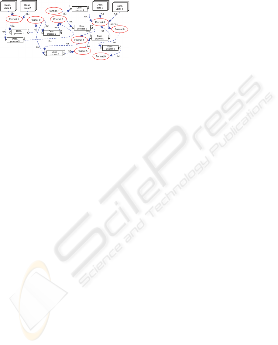
Figure 11: The concept of a resource graph in our context.
process nodes. To elucidate our proposal further, we
provide the following definitions:
• The function subType(f
x
) returns a set of formats,
which are the sub-formats of f
x
.
• The function NumberInputs(p
x
) returns the num-
ber of input parameters of process p
x
.
• A path c
n
=(n
1
, n
2
, ......, n
t
), with for i=1..t, n
i
∈
N, if it exists, is represented by a set of nodes,
which starts with node n
1
and ends with node n
t
.
All other nodes included in this set are covered by
the path.
The definition of a path between two nodes de-
notes a possible matching solution between those
two nodes.
• A set of paths path(n
x
, n
y
)={c
1
, c
2
,......, c
t
} is a
collection of paths, with for i=1..t, a path c
i
in
this collection should be in the form c
i
=(n
x
, ......,
n
y
).
The definition of a set of possible paths between
two nodes represents the set of matching solutions
found between those two nodes.
• A path c
n
=(n
1
, n
2
, ......, n
t
) is simple, if
and only if: for i=2..t-1, if n
i
∈ N
P
, then
NumberInputs(n
i
)=1.
The definition of a simple path corresponds to a
match between two data formats, which does not
require an additional input parameter. Thus, the
path (F2, P2, F3, P5, F4) is a simple path, the
two process nodes, P2 and P5, do, in fact, satisfy
the condition of the simple path, i.e.: NumberIn-
puts(P2)=1 and NumberInputs(P5)=1.
• A path c
n
=(n
1
, n
2
, ......, n
t
) is complex, if and only
if: for i=2..t-1, ∃n
i
∈ N
P
and NumberInputs(n
i
)
> 1.
The definition of a complex path corresponds to
a match between two data formats requiring addi-
tional input parameters. Thus path (F4, P6, F5,
P7, F6) is complex because P6 requires two input
parameters (in addition to the F2 format parame-
ter).
The analysis of compatibility between two
chained processes comes down here to an analysis
of the compatibility between the data formats of the
chained output and input ports of these two processes.
Let us suppose that the data formats f
o
and f
i
are
linked, and that the direction of the data flow is from
f
o
towards f
i
, we can then summarize the different
conformity cases into the four following situations:
1. Perfect Compatibility, with condition if (f
o
= f
i
)
∨ (f
o
∈ subType(f
i
)).
The data format of the output of the first process is
identical to, or is a sub-type of, the data format of
the input of the second process. From a syntactic
point of view, no adaptation is necessary.
2. Compatibility after Adaptation, with condition
if (f
o
6= f
i
) ∧ (f
o
6∈ subType(f
i
)) ∧ (path(f
o
, f
i
) 6= ø)
∧ (∃ c
n
∈ path((f
o
, f
i
)), c
n
is a simple path).
The two data formats are not compatible at first
glance but a path between the two has been found
using an adaptation solution. This adaptation
takes place automatically without recourse to ad-
ditional input parameters.
3. Compatibility with Adaptation’, with condition
if (f
o
6= f
i
) ∧ (f
o
6∈ subType(f
i
)) ∧ (path(f
o
, f
i
) 6= ø)
∧ (∀ c
n
∈ path((f
o
, f
i
)), c
n
is a complex path).
The two data formats are not compatible at first
glance but a path that links them has been found.
However, to apply the adaptation solution addi-
tional input parameters have to be provided.
4. Incompatible, with condition if (f
o
6= f
i
) ∧ (f
o
6∈
subType(f
i
)) ∧ (path(f
o
, f
i
) = ).
This situation is quite clear: the two linked data
formats are not compatible at all, and no path has
been found in the resource graph. Human inter-
vention will be required in such a case. If the
problem of incompatibility is resolved by imple-
menting a specific adapter, the system will be en-
riched by the addition of the adaptation solution
used.
4 PERSPECTIVES AND
CONCLUSIONS
Platform MDWeb offers the possibilities to describe
geographic resource and then use these saved descrip-
tions to localize the corresponding resource. The
workflow component, as presented in this article, is
actually our main research focus, and it’s under con-
struction. The meta-model and the graphical language
for designing workflow chains currently exist only as
prototypes. We now have to construct the resource
ICEIS 2010 - 12th International Conference on Enterprise Information Systems
56

graph based on the proposals we have advanced. We
are aware that the global resource graph may become
substantial and thus its construction and maintenance
may prove cumbersome. The possibility of construct-
ing a local resource graph using templates of business
process chains merits explorations because that may
alleviate this difficulty. Then the conformity cases
need to be formalized and different path-finding al-
gorithms constructed to allow the validation of the in-
termediate level process chains. The next step for us,
consist thus in the verification of the instanced pro-
cess chains, and of course these validated chains then
can be shared and reused by other users. The final part
of the work will be devoted to the dynamic phase, i.e.,
the execution strategy of the valid chain.
REFERENCES
Altintas, I., Lud
¨
ascher, B., Klasky, S., and Vouk, M. A.
(2006). S04 - introduction to scientific workflow man-
agement and the kepler system. In SC, page 205.
Barde, J., Libourel, T., and Maurel, P. (2005). A metadata
service for integrated management of knowledges re-
lated to coastal areas. Multimedia Tools Appl., 25(3).
BioSide (2008). BioSide Community site, Bioside user
guide. v1.0.beta.
Desconnets, J. (2007). Mdweb : outils de catalogage et de
localisation de l’information environnementale. Tech-
nical report, IRD US ESPACE (http://www.mdweb-
project.org).
Desconnets, J., Libourel, T., Clerc, S., and Granouillac, B.
(May 11 2007). Cataloguing for distribution of envi-
ronmental resources. AGILE’07 : 10th International
Conference on Geographic Information Science.
F
¨
urst., F. (October 2002). L’ing
´
enierie ontologique.
Hull, D., Wolstencroft, K., Stevens, R., Goble, C. A.,
Pocock, M. R., Li, P., and Oinn, T. (2006). Taverna:
a tool for building and running workflows of services.
Nucleic Acids Research, 34(Web-Server-Issue).
INPIRE (2008). INSPIRE metadata implementing rules
based on ISO 19115 and ISO 19119. European
Comission.
ISO19115 (2006). Geographic Information : Metadata.
ISO/TC 211.
Lin, Y., Libourel, T., and Mougenot, I. (2009). A work-
flow language for the experimental sciences. ICEIS
09 – 11th International Conference on Enterprise In-
formation Systems.
OGC (2007). Catalog Service for Web. Open Geospatial
Consortium.
OMG (2001). Uml 2.0 superstructure specification.
OMG (2008.2). Business process definition metamodel,
beta 1.
OMG (January 2005). Software process engineering meta-
model specification version 1.1.
OMG (January 2006). Meta Object Facility (MOF) Core
Specification, Version 2.0, formal/06-01-01.
Pierkot, C. (2008). Management of the update of replicated
spatial data. PhD thesis, University of Toulouse,
France.
A PLATFORM DEDICATED TO SHARE AND MUTUALIZE ENVIRONMENTAL APPLICATIONS
57
