
KINEMATIC IDENTIFICATION OF PARALLEL MECHANISMS BY
A DIVIDE AND CONQUER STRATEGY
Sebasti
´
an Durango
a
, David Restrepo
a
, Oscar Ruiz
a
, John Restrepo-Giraldo
b
and Sofiane Achiche
b
a
CAD CAM CAE research laboratory, EAFIT University, Medell
´
ın, Colombia
b
Management Engineering Dept., Technical University of Denmark, Lyngby, Denmark
Keywords:
Parallel mechanisms, Kinematic identification, Robot calibration.
Abstract:
This paper presents a Divide and Conquer strategy to estimate the kinematic parameters of parallel symmetri-
cal mechanisms. The Divide and Conquer kinematic identification is designed and performed independently
for each leg of the mechanism. The estimation of the kinematic parameters is performed using the inverse cali-
bration method. The identification poses are selected optimizing the observability of the kinematic parameters
from a Jacobian identification matrix. With respect to traditional identification methods the main advantages
of the proposed Divide and Conquer kinematic identification strategy are: (i) reduction of the kinematic iden-
tification computational costs, (ii) improvement of the numerical efficiency of the kinematic identification
algorithm and, (iii) improvement of the kinematic identification results. The contributions of the paper are:
(i) The formalization of the inverse calibration method as the Divide and Conquer strategy for the kinematic
identification of parallel symmetrical mechanisms and, (ii) a new kinematic identification protocol based on
the Divide and Conquer strategy. As an application of the proposed kinematic identification protocol the iden-
tification of a planar 5R symmetrical mechanism is simulated. The performance of the calibrated mechanism
is evaluated by updating the kinematic model with the estimated parameters and developing simulations.
1 INTRODUCTION
In mechanisms and manipulators the accuracy of the
end-effector critically depends on the knowledge of
the kinematic model governing the control model
(Zhuang et al., 1998). Therefore, to improve the accu-
racy of a mechanism its kinematic parameters have to
be precisely estimated by means of a kinematic iden-
tification procedure (Renaud et al., 2006).
Kinematic identification is an instance of the robot
calibration problem. The estimation of rigid-body in-
ertial parameters and the estimation of sensor gain
and offset are instances of calibration problems at the
same hierarchical level of the kinematic calibration
problem (Hollerbach et al., 2008).
This paper is devoted to the kinematic identifi-
cation of parallel symmetrical mechanisms. Parallel
mechanisms are instances of closed-loop mechanisms
typically formed by a moving platform connected to
a fixed base by several legs. Each leg is a kinematic
chain formed by a pattern of links, actuated and pas-
sive joints relating the moving platform with the fixed
base. If the pattern of joints and links is the same for
each leg and each leg is controlled by one actuator,
then the parallel mechanism is denoted symmetrical
(Tsai, 1999).
For parallel mechanisms the kinematic identifi-
cation is usually performed minimizing an error be-
tween the measured joint variables and their corre-
sponding values calculated from the measured end-
effector pose through an inverse kinematic model
(Zhuang et al., 1998; Renaud et al., 2006). This
method is preferred for the identification of parallel
mechanisms because:
1. Inverse kinematics of parallel mechanisms is usu-
ally derived analytically avoiding the numerical prob-
lems associated with any forward kinematics solution
(Zhuang et al., 1998; Renaud et al., 2006).
2. The inverse calibration method is considered to
be the most numerically efficient among the identi-
fication algorithms for parallel mechanisms (Renaud
et al., 2006; Besnard and Khalil, 2001).
3. With respect to forward kinematic identification
no scaling is necessary to balance the contribution of
position and orientation measurements (Zhuang et al.,
1998).
In the case of parallel symmetrical mechanisms
167
Durango S., Restrepo D., Ruiz O., Restrepo-Giraldo J. and Achiche S. (2010).
KINEMATIC IDENTIFICATION OF PARALLEL MECHANISMS BY A DIVIDE AND CONQUER STRATEGY.
In Proceedings of the 7th International Conference on Informatics in Control, Automation and Robotics, pages 167-173
DOI: 10.5220/0002911901670173
Copyright
c
SciTePress

the inverse kinematic modeling can be formulated us-
ing independent loop-closure equations. Each loop-
closure equation relates the end-effector pose, the ge-
ometry of a leg, and a fixed reference frame. In conse-
quence, an independent kinematic constraint equation
is formulated for each leg forming the mechanism.
For the case of parallel symmetrical mechanisms the
set of constraint equations is equal to the number of
legs and to the number of degrees of freedom of the
mechanisms. Each kinematic constraint equation can
be used for the independent identification of the pa-
rameters of the leg correspondent to the equation.
The independent identification of the kinematic
parameters of each leg in parallel mechanisms allows
to improve:
1. The numerical efficiency of the identification algo-
rithm (Zhuang et al., 1998).
2. The kinematic calibration performance by the de-
sign of independent experiments optimized for the
identification of each leg.
The independent identification of leg parameters in
parallel mechanisms was sketched in (Zhuang et al.,
1998) and developed for the specific case of Gough
platforms in (Daney et al., 2002; Daney et al., 2005).
However, the idea of the independence in the kine-
matic identification of each leg in a parallel mecha-
nism is not completely formalized.
This article presents a contribution to the im-
provement of the pose accuracy in parallel symmet-
rical mechanisms by a kinematic calibration protocol
based on inverse kinematic modeling and a divide and
conquer strategy. The proposed divide and conquer
strategy takes advantage of the independent kinematic
identification of each leg in a parallel mechanism not
only from a numerical stand point but also from the
selection of the optimal measurement set of poses that
improves the kinematic identification of the parame-
ters of the leg itself.
The layout for the rest of the document is as fol-
lows: section 2 develops a literature review on the in-
verse calibration of parallel mechanisms method, sec-
tion 3 presents the divide and conquer identification
of parallel mechanisms strategy, section 4 develops a
kinematic identification of parallel mechanisms pro-
tocol, section 5 presents the simulated kinematic iden-
tification of a planar 5R symmetrical mechanism us-
ing the identification protocol, finally, in section 6 the
conclusions are developed.
2 LITERATURE REVIEW
The modeling of mechanical systems include the de-
sign, analysis and control of mechanical devices. An
accurate identification of the model parameters is re-
quired in the case of control tasks (Hollerbach et al.,
2008). Instances of models of mechanical systems in-
cludes kinematic, dynamic, sensor, actuators and flex-
ibility models. For parallel mechanisms updating the
kinematic models with accurately estimated param-
eters is essential to achieve precise motion at high-
speed rates. This is the case when parallel mech-
anisms are used in machining applications (Renaud
et al., 2006).
The inverse calibration method is accepted as the
natural (Renaud et al., 2006; Zhuang et al., 1998) and
most numerically efficient (Besnard and Khalil, 2001)
among the identification algorithms for parallel mech-
anisms. The inverse calibration method is based on
inverse kinematic modeling and a external metrolog-
ical system. The calibration is developed minimiz-
ing an error residual between the measured joint vari-
ables and its estimated values from the end-effector
pose though the inverse kinematic model. The deriva-
tion of the inverse kinematic model of parallel mech-
anisms is usually straightforward obtained (Merlet,
2006).
For our Divide and Conquer kinematic calibra-
tion strategy we adopt the inverse calibration method.
The method takes advantage of an intrinsic charac-
teristic of parallel mechanisms: the straightforward
calculation of the inverse kinematics. However, not
all the intrinsic characteristics of parallel mechanisms
are exploited. Specifically, (Zhuang et al., 1998; Ryu
and Rauf, 2001) reported that for parallel mechanism,
methods based on inverse kinematics allow to iden-
tify error parameters of each leg of the mechanism
independently. The independent parameter identifica-
tion of each leg is reported to improve the numerical
efficiency of the kinematic identification algorithm,
(Zhuang et al., 1998). However, it is not reported a
general kinematic identification strategy based on the
independent identification of the legs and its advan-
tages with respect to traditional identification meth-
ods.
This article presents a contribution to the kine-
matic calibration of parallel mechanisms developing a
kinematic identification protocol based on the inverse
calibration method and on the independent identifica-
tion of the parameters of each leg (Divide and Con-
quer strategy).
With respect to traditional identification methods,
our Divide and Conquer strategy has the following ad-
vantages:
1. The identification poses can be optimized to the
identification of reduced sets of parameters (the sets
corresponding to each leg).
2. The independent identification of the parameters
ICINCO 2010 - 7th International Conference on Informatics in Control, Automation and Robotics
168

of each leg improves the numerical efficiency of the
identification algorithms.
3. By 1. and 2. the identified set of parameters is
closer to the real (unknown) set of parameters than
sets identified by other traditional calibration meth-
ods.
The divide and Conquer strategy for the inde-
pendent kinematic identification of the parameters of
each leg in a parallel symmetrical mechanism is pre-
sented in section 3.
3 DIVIDE AND CONQUER
IDENTIFICATION STRATEGY
Parallel symmetrical mechanisms satisfy (Tsai,
1999):
1. The number of legs is equal to the number of de-
grees of freedom of the end-effector.
2. All the legs have an identical structure. This is,
each leg has the same number of active and passive
joints and the joints are arranged in an identical pat-
tern.
In a practical way, the definition of parallel sym-
metrical mechanism covers most of the industrial par-
allel structures. For parallel symmetrical mechanisms
the kinematic identification by inverse kinematics and
a divide and conquer strategy is stated for each leg κ
independently, κ = 1, 2, . . . , n
limbs
.
Given:
1. A set of nominal kinematic parameters of the κth
leg (ϕ
κ
). n
κ
parameters are assumed to be identified:
ϕ
κ
=
ϕ
κ,1
. . . ϕ
κ,n
κ
T
.
(1)
2. An inverse kinematic function g
κ
relating the κth
active joint variable (q
κ
) with the end-effector pose
(r). For the jth pose of the mechanism the inverse
function of the κth leg is defined to be:
g
j
κ
: ϕ
κ
×r
j
→ q
j
κ
,
j = 1, 2, . . . , N.
(2)
3. A set of N end-effector measured configurations
(
ˆ
R
κ
) for the identification of the κth leg:
ˆ
R
κ
=
ˆ
r
1
κ
···
ˆ
r
N
κ
T
.
(3)
4. A set of measured input variables (
ˆ
Q
κ
) correspond-
ing to the set of end-effector measurements (
ˆ
R
κ
):
ˆ
Q
κ
=
ˆ
q
1
κ
···
ˆ
q
N
κ
T
.
(4)
Goal. To find the set of unknown (real) kinematic
parameters (
¯
ϕ
κ
) that minimizes an error between the
measured joint variables (
ˆ
Q
κ
) and their correspond-
ing values (
¯
Q
κ
) estimated from the measured end-
effector poses by the inverse kinematic model g
κ
. The
problem can be formally stated as the following non-
linear minimization problem:
¯
ϕ
κ
:
N
∑
j=1
ˆ
Q
κ
−
¯
Q
κ
ˆ
R
κ
, ϕ
κ
2
is minimum,
subject to : R
κ
⊂ W
R
,
W
R
is the usable end −effector workspace.
(5)
The optimization problem is constrained by the
useful workspace (a workspace without singularities)
of the mechanism.
A kinematic identification of parallel symmetrical
mechanisms protocol based on the Divide and Con-
quer identification strategy is developed in section 4.
4 KINEMATIC IDENTIFICATION
PROTOCOL
Based on the Divide and Conquer strategy for
the kinematic identification of parallel symmetrical
mechanisms (section 3) the following kinematic iden-
tification protocol (Figure 1) is proposed.
1. Given the nominal parameters of the κth leg (ϕ
κ
,
Eq. 1) and the correspondent inverse kinematic func-
tion (g
κ
, Eq. 2) to calculate the κth Jacobian identifi-
cation matrix of a representative set of postures of the
usable workspace:
C
κ
(W
R
, ϕ
κ
) =
∂g
κ
(W
R
, ϕ
κ
)
∂ϕ
T
κ
. (6)
2. Given the Jacobian identification matrix calculated
in the first step to select an optimal set of postures
(R
κ
(C
κ
)) for the kinematic identification of the κth
leg. The set of postures is selected searching the im-
provement of the observability of the set of parame-
ters ϕ
κ
. To select the poses we adopt the active cali-
bration algorithm developed by (Sun and Hollerbach,
2008) that reduces the complexity of computing an
observability index reducing computational time for
finding optimal poses. The optimized identification
set of postures is then defined in the following man-
ner:
R
κ
: O
1
(R
κ
) is maximal,
O
1
(R
κ
) =
n
κ
√
s
1
s
2
···s
n
κ
n
κ
,
R
κ
⊂ W
R
,
(7)
KINEMATIC IDENTIFICATION OF PARALLEL MECHANISMS BY A DIVIDE AND CONQUER STRATEGY
169
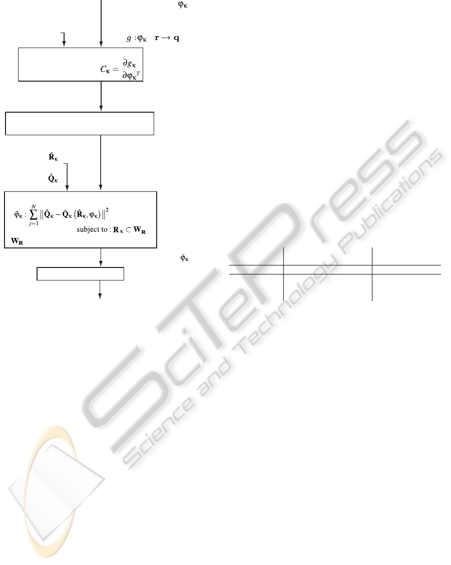
Calculation of the Jacobian
identification matrix
Pose selection by Active Robot Calibration
Algorithm (Sun and Hollerbach, 2008)
Estimation of kinematic parameters process
is the end-effector usable workspace
End-effector usable
workspace, W
R
Identified parameters,
Nominal parameters,
Inverse kinematics equation
for the κth leg:
x
Jacobian identification
matrix, C
Κ
Updated kinematic model
Update kinematic model
Set of optimal identification
postures, R
Κ
Set of end-effector external
measurements,
Set of active-joint
measurements,
is minimum,
,
.
Figure 1: Kinematic identification of parallel symmetrical
mechanisms protocol.
were O
1
is an observability index of the identifica-
tion matrix (C
κ
(R
κ
, ϕ
κ
)) of the κth leg, n
κ
is the num-
ber of parameters to be identified in the κth leg, and
s
1
, s
2
. . . , s
n
κ
are the singular values of the identifica-
tion matrix C
κ
. As a rule of thumb, in order to sup-
press the influence of measurement noise, the number
of identification poses should be two or three times
larger than the number of parameters to be estimated
(Jang et al., 2001).
3. Given the optimized set of identification postures
obtained in the second step and the correspondent sets
of active joint (
ˆ
Q
κ
) and end-effector (
ˆ
R
κ
) measure-
ments to solve the optimization problem defined on
Eq. 5 for the identification of the kinematic parame-
ters (ϕ
κ
) of the κth leg.
4. Given the identified set of parameters of the κth
leg obtained in the third step to update the kinematic
model of the parallel mechanism.
The protocol is repeated until all the legs in the
mechanism are identified.
With respect to traditional identification algo-
rithms for the kinematic identification of parallel
mechanism (Renaud et al., 2006; Zhuang et al., 1998)
the proposed kinematic identification protocol has the
following advantages:
1. Reduction of the kinematic identification compu-
tational costs. If a linear least-squares estimation of
the kinematic parameters is used to solve the identi-
fication problem (Eq. 5), then the correction to be
applied to the kinematic parameters (∆ϕ) can be esti-
mated iteratively as (Hollerbach and Wampler, 1996):
∆ϕ =
C
T
C
−1
C
T
∆Q. (8)
The computational cost of the matrix inversion
(C
T
C)
−1
is reduced proportionally to the square of
the number of legs of the mechanism, Table 1.
2. Improvement of the numerical efficiency of the
kinematic identification algorithm by the independent
identification of the parameters of each leg.
3. Improvement of the kinematic identification by the
design of independent experiments optimized for the
identification of each leg.
Table 1: Computational and measurement costs of kine-
matic identification.
Traditional kinematic Divide and conquer
identification identification
Regressor C
T
C(N n
limbs
× N n
limbs
) C
T
κ
C
κ
(N × N)
Computational
cost (Matrix ∝ N
3
n
limbs
3
∝ N
3
n
limbs
inversion)
The kinematic identification of parallel mecha-
nisms protocol is used in the simulated identification
of a planar 5R symmetrical mechanism in section 5.
5 RESULTS
The results on kinematic identification of parallel
mechanisms by a Divide and Conquer strategy are
presented using a case study: the simulated kinematic
identification of the planar 5R symmetrical parallel
mechanism.
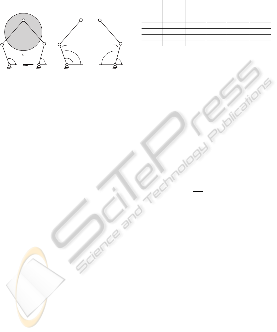
The planar 5R symmetrical mechanism (Figure 2)
has two degrees-of-freedom (DOF) that allows it to
position the end-effector point (P) in the plane that
contains the mechanism. The mechanism is formed
by two driving links (l
1
and l
2
) and a conducted dyad
(L
1
and L
2
), Figure 2. The planar 5R symmetrical
mechanism is an instance of the parallel symmetrical
mechanisms defined in section 3. A complete charac-
terization of the assembly configurations (Cervantes-
S
´
anchez et al., 2000), kinematic design (Cervantes-
S
´
anchez et al., 2001; Liu et al., 2006a; Liu et al.,
2006b; Liu et al., 2006c), workspace (Cervantes-
S
´
anchez et al., 2001; Cervantes-S
´
anchez et al., 2000;
Liu et al., 2006a), singularities (Cervantes-S
´
anchez
et al., 2001; Cervantes-S
´
anchez et al., 2000; Liu et al.,
ICINCO 2010 - 7th International Conference on Informatics in Control, Automation and Robotics
170
2006a) and performance atlases (Liu et al., 2006b) are
reported. However, no research is reported on kine-
matic identification.
A
1
P(x,y)
X
Y
θ
1
l
1
l
2
A
2
L
1
L
2
θ
2
P(x,y)
l
2
A
2
L
2
θ
2
ψ
2
P(x,y)
A
1
θ
1
l
1
L
1
ψ
1
Leg
1
Leg
2
Figure 2: Planar 5R symmetrical mechanism.
The kinematic identification of the planar 5R
symmetrical mechanism is simulated using the kine-
matic identification of parallel symmetrical mecha-
nisms protocol (section 4) under the following con-
ditions:
1. A linear model is assumed for the active joint A
κ
:
θ
κ
= kψ
κ
+ γ
κ
, (9)
where the k
κ
represent the joint gain, γ
κ
is the joint
offset, ψ
κ
is the measured active joint angle and θ
κ
is
the active joint angle, κ = 1, 2.
2. In parallel mechanisms the principal source of er-
ror in positioning is due to limited knowledge of the
joint centers, leg lengths and active joint parameters
(Daney et al., 2002). In consequence, the parameters
to be estimated are the attachment points (A
κ
), the leg
lengths (l
κ
, L
κ
), and the joint gain and offset (k
κ
, γ
κ
),
κ = 1, 2:
ϕ
κ
= [l
κ
L
κ
A
κx
A
κy
k
κ
γ
κ
]
T
. (10)
3. The external parameters associated with the mea-
suring device will not be identified. For the exter-
nal measuring system this implies that its position is
known and coincident with the reference frame X −Y
and the measurement target is coincident with the
end-effector point.
4. The nominal kinematic parameters of the mecha-
nism are disturbed adding a random error with normal
distribution and a standard deviation σ. The nominal
and disturbed parameters are shown in Table 2.
5. The constrain equation of the inverse kinematics
is defined independently for the κth leg (Liu et al.,
2006a), κ = 1, 2:
L
κ
2
= (x −l
κ
cosθ
κ
−A
κx
)
2
+
(y −l
κ
sinθ
κ
−A
κy
)
2
. (11)
6. The end-effector and joint workspace are lim-
ited by the maximal inscribed workspace (MIW),
Table 2: Planar 5R symmetrical mechanism. Nominal and
real (disturbed) parameters.
Nominal Real Nominal Real
value value value value
A
1x
[m] -0.5000 -0.4988 A
2x
[m] 0.5000 0.4961
A
1y
[m] 0.0000 0.0028 A
2y
[m] 0.0000 0.0066
k
1
1.0000 1.004 k
2
-1.0000 -0.9984
γ
1
[rad] 0.0000 0.0048 γ
2
[rad] 3.1416 3.1418
l
1
[m] 0.7500 0.7507 l
2
[m] 0.7500 0.7559
L
1
[m] 1.1000 1.0995 L
2
[m] 1.1000 1.0959
Figure 2. The MIW corresponds to the maximum
singularity-free-end-effector workspace limited by a
circle (Liu et al., 2006c).
7. Each leg is identified using a set of 18 postures
of the mechanism to measure the end-effector posi-
tion and the corresponding active joint variable. The
designed sets of identification postures in the end-
effector workspace are presented in Figure 4b.
8. The set of end-effector measurements (
ˆ
R
κ
) and
its corresponding active joint measurements (
ˆ
Q
κ
) are
simulated using forward kinematics and adding ran-
dom disturbances with normal distribution and stan-
dard deviation σ = 1 ·10
−4
.
9. A linearization of the inverse kinematics is used for
iteratively solving the non-linear optimization prob-
lem (Eq. 5), then, for the jth identification pose the
identification problem of the κth leg is in the follow-
ing form:
∆q
j
κ
=
∂g
j
κ
∂ϕ
κ
∆ϕ
κ
= C
j
κ
∆ϕ,
∆q
j
κ
=
ˆ
q
j
κ
−
¯
q
j
κ
,
∆ϕ
κ
=
¯
ϕ
κ
−ϕ
κ
.
(12)
Using N = 18 measurements to identify the set of pa-
rameters ϕ
κ
the identification problem is stated in the
following manner:
∆Q
κ
= C
κ
∆ϕ
κ
,
C
κ
=
C
1
κ
···C
N
κ
T
,
∆Q
κ
=
∆q
1
κ
···∆q
N
κ
T
,
(13)
were C
κ
is the identification matrix of the κth leg. The
parameters of the κth leg can be updated using a lin-
ear least-squares solution of Eq. 13, (Hollerbach and
Wampler, 1996):
∆ϕ
κ
= (C
T
κ
C
κ
)
−1
C
T
κ
∆Q
κ
. (14)
10. An alternative traditional kinematic identification
by inverse kinematic modeling is calculated and used
as a comparison with respect to the proposed kine-
matic identification protocol. The traditional identifi-
cation is performed by means of a set of 36 optimized
postures selected in order to maximize the observabil-
ity of the total identification matrix. The observability
KINEMATIC IDENTIFICATION OF PARALLEL MECHANISMS BY A DIVIDE AND CONQUER STRATEGY
171
|φ
real
−φ
nominal
|
|φ
real
−φ
traditional Identif.
|
|φ
real
−φ
D&C Identif.
|
0
1
2
3
4
5
6
l
1
l
2
L
1
L
2
∆ φ [mm]
a. Link lengths
0
1
2
3
4
5
6
7
A
1x
A
1y
A
2x
A
2y
∆ φ [mm]
b. Position of fixed joints
1
2
0
1
2
3
4
5
k k
γ
1
γ
2
∆ φ
c. Active joint parameters
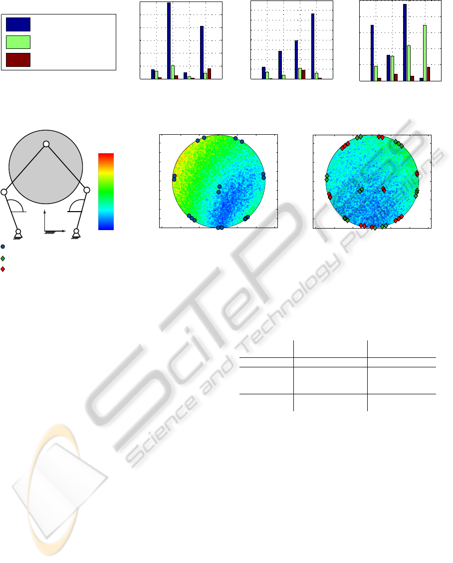
Figure 3: Planar 5R mechanism. Residual errors in the kinematic parameters before and after calibration.
−0.6 −0.4 −0.2 0 0.2 0.4 0.6
0.7
0.8
0.9
1
1.1
1.2
1.3
1.4
1.5
−0.6 −0.4 −0.2 0 0.2 0.4 0.6
0.7
0.8
0.9
1
1.1
1.2
1.3
1.4
x [m]
y [m]
x [m]
y [m]
1.19
0.89
6.68e
-03
0.30
0.60
RMSE
[mm]
A
1
P(x,y)
X
Y
ψ
1
l
1
l
2
A
2
L
1
L
2
ψ
2
a) Calibration with traditional
identification method.
b) Calibration with divide and conquer
identification strategy.
Poses for traditional identification.
Poses for D&C identification of left leg.
Poses for D&C identification of rigth leg.
Figure 4: Planar 5R mechanism. Estimated end-effector local root mean square error for the maximal inscribed workspace
(MIW) after calibration.
was defined as the Eq. 7. The designed set of identi-
fication postures is presented in Figure 4a.
The results of the kinematic identification under
these conditions are presented in Figure 3 (residual
errors in kinematic parameters before and after cali-
bration). The residual errors are calculated as the dif-
ference between the real (virtually disturbed) param-
eters and the estimated parameters. Finally, Figure 4
presents the estimated local root mean square error for
the MIW after calibration and the selected postures
for kinematic identification. Additionally the compu-
tational and measurement identification costs are es-
timated for the identification of the planar 5R parallel
mechanism, Table 3. The measurement costs of the
Divide and Conquer strategy are incremented with re-
spect to a traditional identification method. The incre-
ment of the measurements is required because each
leg requires an independent set of end-effector mea-
surements. In the case of a traditional identification
the set of end-effector measurements is common to all
the legs. In despite of the measurement increment the
Divide and Conquer identification results in a supe-
rior estimation with respect to a traditional kinematic
identification methods (Renaud et al., 2006; Zhuang
et al., 1998). The conclusions of the paper are pro-
posed in section 6.
Table 3: Planar 5R symmetrical mechanism. Computa-
tional and measurement costs of kinematic identification.
Traditional kinematic Divide and conquer
identification identification
Regressor C
T
C(36 ×36) C
T
κ
C
κ
(18 × 18)
Computational
cost (Matrix ∝ 18
3
·2
3
∝ 18
3
·2
inversion)
Measurement 2 ·18 ·2 = 72 18 ·2(2 + 1) = 108
cost
6 CONCLUSIONS
This article presents a new (Divide and Conquer)
strategy for the kinematic identification of parallel
symmetrical mechanisms. The new strategy devel-
ops a formalization of the inverse calibration method
proposed by (Zhuang et al., 1998). The identification
strategy (section 3) is based on the independent identi-
fication of the kinematic parameters of each leg of the
parallel mechanism by minimizing an error between
the measured active joint variable of the identified leg
and their corresponding value, estimated through an
inverse kinematic model. With respect to traditional
identification methods the Divide and Conquer strat-
egy presents the following advantages:
1. Reduction of the kinematic identification computa-
ICINCO 2010 - 7th International Conference on Informatics in Control, Automation and Robotics
172

tional costs,
2. Improvement of the numerical efficiency of the
kinematic identification algorithm and,
3. Improvement of the kinematic identification re-
sults.
Based on the Divide and Conquer strategy, a new
protocol for the kinematic identification of parallel
symmetrical mechanisms is proposed (section 4, Fig-
ure 1). For the selection of optimal identification pos-
tures the protocol adopts the active robot calibration
algorithm of (Sun and Hollerbach, 2008). The main
advantage of the active robot calibration algorithm is
the reduction of the complexity of computing an ob-
servability index for the kinematic identification, al-
lowing to afford more candidate poses in the optimal
pose selection search. The kinematic identification
protocol summarizes the advantages of the Divide and
Conquer identification strategy and the advantages of
the active robot calibration algorithm.
The kinematic identification protocol is demon-
strated with the simulated identification of a planar
5R symmetrical mechanism (section 5). The perfor-
mance of our identification protocol is compared with
a traditional identification method obtaining an im-
provement of the identification results (Figs. 3, 4).
ACKNOWLEDGEMENTS
The authors wish to acknowledge the financial sup-
port for this research by the Colombian Administra-
tive Department of Sciences, Technology and Innova-
tion (COLCIENCIAS), grant 1216-479-22001.
REFERENCES
Besnard, S. and Khalil, W. (2001). Identifiable parameters
for parallel robots kinematic calibration. In IEEE In-
ternational Conference on Robotics and Automation,
2001. Proceedings 2001 ICRA, volume 3.
Cervantes-S
´
anchez, J. J., Hern
´
andez-Rodr
´
ıguez, J. C., and
Angeles, J. (2001). On the kinematic design of the 5r
planar, symmetric manipulator. Mechanism and Ma-
chine Theory, 36(11-12):1301 – 1313.
Cervantes-S
´
anchez, J. J., Hern
´
andez-Rodr
´
ıguez, J. C., and
Rend
´
on-S
´
anchez, J. G. (2000). On the workspace, as-
sembly configurations and singularity curves of the
rrrrr-type planar manipulator. Mechanism and Ma-
chine Theory, 35(8):1117 – 1139.
Daney, D., Lorraine, I., and LORIA, V. (2002). Op-
timal measurement configurations for Gough plat-
form calibration. In IEEE International Confer-
ence on Robotics and Automation, 2002. Proceedings.
ICRA’02, volume 1.
Daney, D., Papegay, Y., and Madeline, B. (2005). Choos-
ing measurement poses for robot calibration with the
local convergence method and Tabu search. The Inter-
national Journal of Robotics Research, 24(6):501.
Hollerbach, J., Khalil, W., and Gautier, M. (2008). Springer
Handbook of Robotics, Model Identification. Springer.
Hollerbach, J. and Wampler, C. (1996). The calibration
index and taxonomy for robot kinematic calibration
methods. The International Journal of Robotics Re-
search.
Jang, J., Kim, S., and Kwak, Y. (2001). Calibration of geo-
metric and non-geometric errors of an industrial robot.
Robotica, 19(03):311–321.
Liu, X., Wang, J., and Pritschow, G. (2006a). Kinematics,
singularity and workspace of planar 5r symmetrical
parallel mechanisms. Mechanism and Machine The-
ory, 41(2):145 – 169.
Liu, X., Wang, J., and Pritschow, G. (2006b). Performance
atlases and optimum design of planar 5r symmetrical
parallel mechanisms. Mechanism and Machine The-
ory, 41(2):119 – 144.
Liu, X., Wang, J., and Zheng, H. (2006c). Optimum design
of the 5r symmetrical parallel manipulator with a sur-
rounded and good-condition workspace. Robotics and
Autonomous Systems, 54(3):221 – 233.
Merlet, J. (2006). Parallel Robots. Springer Netherlands,
second edition.
Renaud, P., Vivas, A., Andreff, N., Poignet, P., Martinet, P.,
Pierrot, F., and Company, O. (2006). Kinematic and
dynamic identification of parallel mechanisms. Con-
trol Engineering Practice, 14(9):1099–1109.
Ryu, J. and Rauf, A. (2001). A new method for fully
autonomous calibration of parallel manipulators us-
ing a constraint link. In 2001 IEEE/ASME Inter-
national Conference on Advanced Intelligent Mecha-
tronics, 2001. Proceedings, volume 1.
Sun, Y. and Hollerbach, J. (2008). Active robot calibration
algorithm. In Robotics and Automation, 2008. ICRA
2008. IEEE International Conference on, pages 1276–
1281.
Tsai, L. (1999). Robot analysis: the mechanics of serial
and parallel manipulators. Wiley-Interscience.
Zhuang, H., Yan, J., and Masory, O. (1998). Calibration
of Stewart platforms and other parallel manipulators
by minimizing inverse kinematic residuals. Journal of
Robotic Systems, 15(7).
KINEMATIC IDENTIFICATION OF PARALLEL MECHANISMS BY A DIVIDE AND CONQUER STRATEGY
173
