A CASTOR WHEEL CONTROLLER FOR DIFFERENTIAL DRIVE
WHEELCHAIRS
Bernd Gersdorf
Safe and Secure Cognitive Systems, German Research Center for Artificial Intelligence, Bremen, Germany
Shi Hui
SFB/TR8 Spatial Cognition, University of Bremen, Germany
Keywords:
Differential drive vehicle, Electric wheelchair, Castor wheel, Motion controller, Force compensation.
Abstract:
This paper describes a motion controller for differential drive vehicles with a compensation for castor wheel
turn forces. The controller has been developed for electric wheelchairs with two front castor wheels, which
require large steering forces to move into the direction given by the joystick in situations where a sharp turn
of the castor wheels is needed. It computes the required forces to turn the castor wheels and modifies the drive
request adequately. This also helps physical or cognitive impaired users who otherwise have to compensate
castor turn forces manually using the joystick, which requires fast reaction time (e.g. when the castor wheels
turn quickly into the driving direction) to avoid collisions.
1 INTRODUCTION
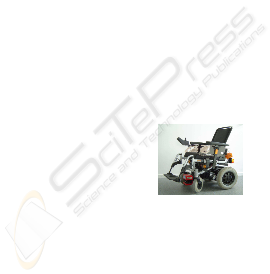
Figure 1 presents the intelligent wheelchair ROLLAND
(Lankenau and R¨ofer, 2001) based on a Meyra
wheelchair of the model CHAMP (Meyra Ortopedia,
2010). As many other electric wheelchairs, CHAMP
uses pneumatic tires for both back differential drive
wheels and front castor wheels to achieve comfort-
able indoor and outdoor driving. The configuration
of back differential drive and two front castor wheels
is probably the most frequently used one for electric
wheelchairs. With the large ground contact area of
the castor wheels, the high load (typical 160kg for
the wheelchair with the driver, about one third on the
front axis), and the tire material (rubber), the addi-
tional force to change the angle of the castor wheel
is significant, especially when maneuvering at low
speed in a narrow environment. Recently, an empiri-
cal study (reference skipped) on the evaluation of the
safety assistant modul developed for ROLLAND was
carried out, which monitors the surrounding environ-
ment using sensor data gathered by the equipped laser
scanners and brakes in time if an obstacle is danger-
ously close to the wheelchair. During the experiment
a common phenomenon was observed: after the in-
tervention of the safety assistant, the participants at-
tempted to regain control over the wheelchair by givi-
Figure 1: The intelligent wheelchair ROLLAND.
ng driving commands via the joystick, but the
wheelchair did not drivein the direction they expected
or did not move at all.
The primary reason for such problems is that the
wheelchair requires a lot of motor force to turn the
castor wheels, if the wheelchair starts in a standing
position with castor wheels positioned in a blocking
state (i.e., the two castor wheels stand transversely to
the required drive direction). Moreover, users often
change the joystick command if the wheelchair does
not react to the previously given command, as most
participants did in the above study. As a result they
tried to give the wheelchair some arbitrary commands
174
Gersdorf B. and Hui S. (2010).
A CASTOR WHEEL CONTROLLER FOR DIFFERENTIAL DRIVE WHEELCHAIRS.
In Proceedings of the 7th International Conference on Informatics in Control, Automation and Robotics, pages 174-179
DOI: 10.5220/0002913101740179
Copyright
c
SciTePress
via the joystick or pressed the joystick powerfully,
which caused an even less expected behaviour of the
wheelchair. One solution to this problem, and as the
focus of the current paper, is to apply a castor wheel
controller, which enables the wheelchair to adjust cas-
tor wheels correctly, such that the time delay to realize
the requested drive command can be reduced in those
situations, and the joystick can remain in a stable po-
sition.
Castor wheels have been investigated in the liter-
ature mainly to model and minimize wheel shimmy
(see (de Falco et al., 2009), (Brearley, 2009), (Kau-
zlarich et al., 2000)). In (Kauzlarich et al., 1984), cas-
tor turn forces are compared for different grounds and
tire materials, but without a projection of these forces
to the differential drive of an electric wheelchair.
Therefore no compensation of these forces is dis-
cussed in that work.
This paper is structured as follows: We begin in
Section 2 with the kinematic model for differential
drive wheelchair with two front castor wheels, and
introduce a model to predict castor turn forces and
discuss possible compensation. Section 3 explains
the integration of the castor force compensation into
ROLLAND. Section 4 discusses some test results by
comparing the wheelchair behaviour with and without
the castor controller. Before concluding in Section 6
we discuss some related approaches in Section 5.
2 A KINEMATIC MODEL
We are going to present a kinematic model of cas-
tor turn forces for differential drive wheelchairs with
two front castor wheels. The castor wheel angles are
essential for the required turn forces, thus should be
discussed first.
2.1 Castor Wheel Angles
C
Forward
α
υ
ω
b
r
a a
′
c
b
′
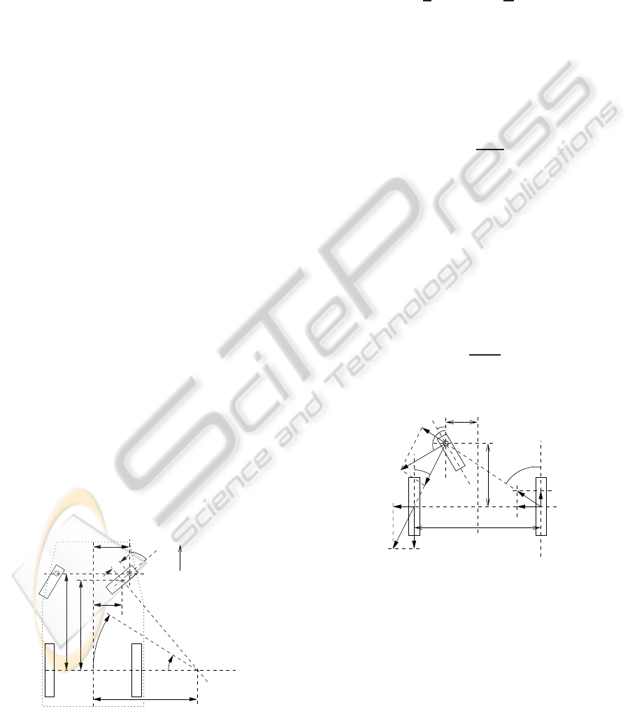
Figure 2: Determination of castor wheel angles.
To compute the required force to turn the castor
wheels, the castor angles must be computed based on
the current driving request. The motion state of dif-
ferential drive vehicles can be described by its rota-
tional speed ω (rad/s) and translational speed υ (m/s)
measured at the center point C between the powered
wheels. The radius r (see Figure 2) is determined by
υ
r
= ω ⇔ r =
υ
ω
(1)
However, there is always a small gap c between a cas-
tor’s ground touch point and the intersection of its
steering axis with the ground plane (also called trail).
Furthermore, the steering axis inclination is usually
0 or almost 0 for castor wheels, and can be assumed
to be 0. If c equals 0, the angle of the castor can be
obtained (using trigonometry) by
tanα =
r− b
a
(2)
For 0 < c ≪ a (as usual), the castor wheel angle α
obtained by Equation 2 is already a good approxima-
tion. However, a higher precision α
′
can be obtained
using the ground touch point at distances a
′
and b
′
derived from the first estimation of the castor wheel
angle α and the value of the gap c (see Equation 5),
with which more precise castor turn forces can be cal-
culated.
a
′
= a− c∗ cosα (3)
b
′
= a− c∗ sinα (4)
tanα
′
=
r− b
′
a
′
(5)
2.2 Castor Turn Forces
S
R
a τ
R
b
θ
F
L
F
l
α
F
τ
L
F
R
d
F
r
S
L
Figure 3: Castor turn force F projected to differential drive
wheels.
Figure 3 shows the geometry of the ROLLAND electric
wheelchair as an example for a differential drive robot
with two castor wheels. Let the castor turn force F be
the force that is required to start the castor wheel to
swivel without rotating the wheel and applied at the
castor steering joint. This force must be applied per-
pendicular to the drivingdirection of the castor wheel.
F can be split into
F = F
ground
+ F
joint
(6)
A CASTOR WHEEL CONTROLLER FOR DIFFERENTIAL DRIVE WHEELCHAIRS
175

where F
ground
represents the friction between the
ground and the tire at the ground touching point, and
F
joint
the friction inside the turning joint. The joint
is typically so constructed that F
joint
≪ F
ground
. A
difference between sticking and gliding forces could
not be observed, due to the plasticity of the tire. As
frictional forces grow proportionally with the normal
force between the surfaces, the castor turn forces can
be described as
F = c
castor
L (7)
where L is the load of the castor wheel and c
castor
is constant for a given wheelchair and ground mate-
rial. Equation 7 must be understood as an upper limit
of the required castor force. A rolling castor wheel
requires much smaller turn forces, which should be
considered by the castor controller (see Section 3).
The castor turn force can be projected to the forces
of the two differential drive wheels, F
L
and F
R
(see
Figure 3):
θ = α±
π
2
(8)
¯
F =
¯
F
l
+
¯
F
r
(9)
F
L
= F
l
cosτ
l
(10)
tanτ
L
=
a
b−
d
2
(11)
F
R
= F
r
cosτ
r
(12)
tanτ
R
=
a
b+
d
2
(13)
+ or − in Equation 8 is chosen depending on the in-
tended castor steering direction (left or right swivel).
Equation 9 splits the castor correction force
¯
F into
forces of the differential drive wheels. The left en-
gine produces
¯
F
l
as the sum of the motor force
¯
F
L
and
a shearing force
¯
S
L
(see Figure 3). The left engine
force F
L
is computed by Equations 10 and 11, and the
right one by Equations 12 and 13.
M
b
M
M
r
l
r
p
q
M
l
M
f
Figure 4: Mass distribution to castor and differential drive
wheels.
Figure 4 shows the center of mass M of the
wheelchair at the point with a distance of p to the back
axis. The back wheels are connected with springs to
the chassis, such that both wheels can be assumed
to carry the same weight that sums up to M
b
at the
back axis center. The front wheels carry the remain-
ing mass M
f
, giving the following mass distribution:
M
f
= M
p
p+ q
(14)
M
l
=
r
l + r
M
f
(15)
M
r
=
l
l + r
M
f
(16)
The values for p, l, and r can be obtained from the
ground touch points as in Figure 2.
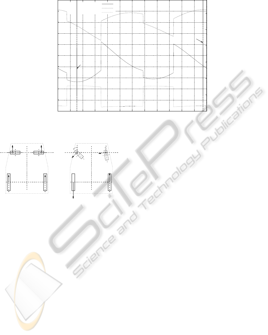
2.3 Maximal Castor Turn Forces
Using the kinematic model of Sections 2.1 and 2.2,
Figure 5 gives an overview of the forces required by
the differential drive vehicle using the geometry of
the Meyra CHAMP wheelchair (in mm: d = 585, p =
160, a = 470, b = 42). For each value of the left cas-
tor angle (x-axis), the diagram shows the angle of
the right castor wheel, which maximises the required
correction force for one of the two differential drive
motors. The force factor (right y-axis in Figure 5)
is the relation between the required motor force and
the standard situation in the left diagram of Figure
6, where castor turn forces and engine forces are all
equal, and the castor wheels are in a blocking state
when drivingforward. The diagram in Figure 5 shows
two symmetric maximal force factors −2.21 (left en-
gine) and 2.21 (right engine). The −2.21 maximum
for the left drive wheel is also shown in the right
diagram of Figure 6 with castor angles L = 46.08
◦
,
R = 8.28
◦
.
3 MOTION CONTROLLER
The kinematic model described in Section 2 has
been implemented and integrated into the wheelchair
ROLLAND in two ways:
• as an add-on for a classical proportional-integral
(PI) controller using odometry information to
control translational and rotational wheelchair
speed (used for autonomous driving).
• as a pure castor force compensation controller to
support joystick driving.
Although the tests reported in Section 4 have been run
with the pure castor controller, both controllers have
been implemented using the following principles:
1. The castor controller applies a slowly growing
correction force. This helps to adapt to different
ICINCO 2010 - 7th International Conference on Informatics in Control, Automation and Robotics
176
-60
-30
0
30
60
90
120
150
180
210
240
0 30 60 90 120 150 180 210 240 270 300 330 360
-4
-3
-2
-1
0
1
2
right castor angle [degree]
engine force [factor]
left castor angle [degree]
right=1.23
left=-2.21
left=-1.23
right=2.21
left engine force
right engine force
right castor angle
Figure 5: Castor angles with maximal differential drive load.
R
L
Figure 6: Castor correction forces in standard (left) and
maximized situation (right).
frictional forces for varying undergrounds, stand-
ing or rolling castor wheels. It smoothly applies
forces for the transition from standing still (no
correction forces applied) to driving (correction
applied).
2. The correction force will be significantly reduced,
if the castor wheel turns too fast.
3. The correction force is reduced, when the differ-
ence between actual and requested castor angle is
small.
4. If the given command changes the driving direc-
tion, the control intensity is reduced. A control in-
tensity built for a specific driving direction should
not be applied for a completely different driving
direction.
5. The correction force of the controller is reduced to
zero, if one of the castor correction forces changes
its sign (the castor angle has crossed its target an-
gle). This allows to reach the target castor angle
exactly and reduces oscillations around the ideal
castor angle.
6. The mass distribution to each individual wheel
can be significantly influenced by the differential
drive forces. The Meyra CHAMP, for example,
has an independent wheel suspension using a trail-
ing arm for each wheel. The forward torque of a
wheel moves the trailing arm and its wheel down-
ward, which increases the load of the castor wheel
on the opposite side. The measurements of this ef-
fect have been used in the controller to correct the
mass distribution described in Figure 4.
7. If the differential drive stands still, the engine
torques grow nonlinear with the given driving
command. The relation between them has been
measured and recorded in a table to apply correct
forces.
The combination of the castor controller with a PI-
controller requires to join the drive requests produced
by both controllers. A brief impression can be ob-
tainded by the following two principles:
• For small deviating castor angles, the influence of
the castor controller should be small. This gives
priority to the PI-controller.
• Correction forces of the castor controller are sub-
tracted from integral parts of the PI-controller.
This gives priority to the castor controller, if cas-
tor wheels are in a blocking state.
A CASTOR WHEEL CONTROLLER FOR DIFFERENTIAL DRIVE WHEELCHAIRS
177
-0.5
0
0.5
1
1.5
2
0 1000 2000 3000 4000 5000 6000 7000
rad/s or rad
time in ms
(3) 50% engine force
(5) 20% engine force
(1)
(2)
(6)
(4)
(1) castor left angle (rad)
(2) castor right angle (rad)
(3) steering (blocked, rad/s)
(4) rotation (blocked, rad/s)
(5) steering (unblocked, rad/s)
(6) rotation (unblocked, rad/s)
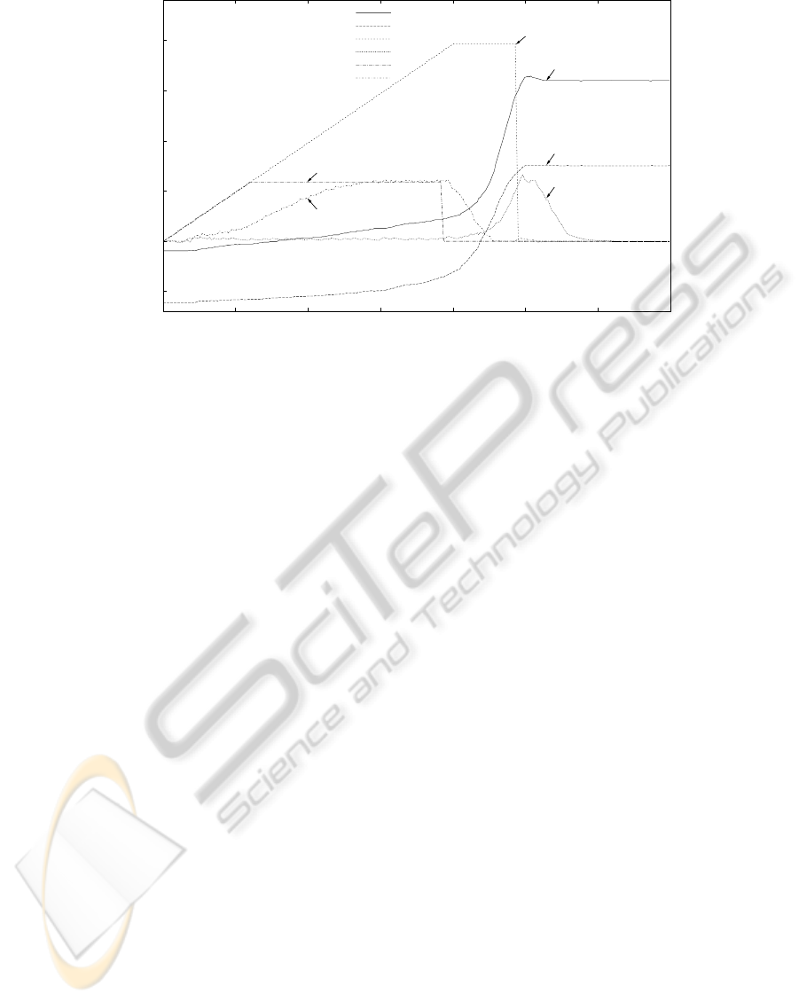
Figure 7: Wheelchair behaviour for a left turn with blocking or adjusted castor wheels.
4 TEST RESULTS
In order to evaluate the influence of the pure castor
wheel controller, a number of tests have been carried
out using the wheelchair ROLLAND. In the following
we are going to discuss some test results.
The test shown in Figure 7 compares the reaction
of the wheelchair between blocked and unblocked
castor wheels while making a left turn without a cas-
tor controller. The steering command for blocked (3)
and unblocked (5) castor wheels is slowly increased
to a level that moves the wheelchair. With unblocked
castor wheels, the engine force can be limited to 20%
(5) to reach a wheelchair turn speed of about 0.6 rad/s
(6). For blocked wheels, the engine force must be in-
creased to 50% (3) to let the castor wheels turn around
(angles are shown in (1) and (2)). In this case, the
castor wheels start to swivel after about 5 seconds.
The steering command is then reduced to zero (dur-
ing this measurement) to avoid a too fast rotation of
the wheelchair. Usually, the steering command must
be reduced by the wheelchair user manually.
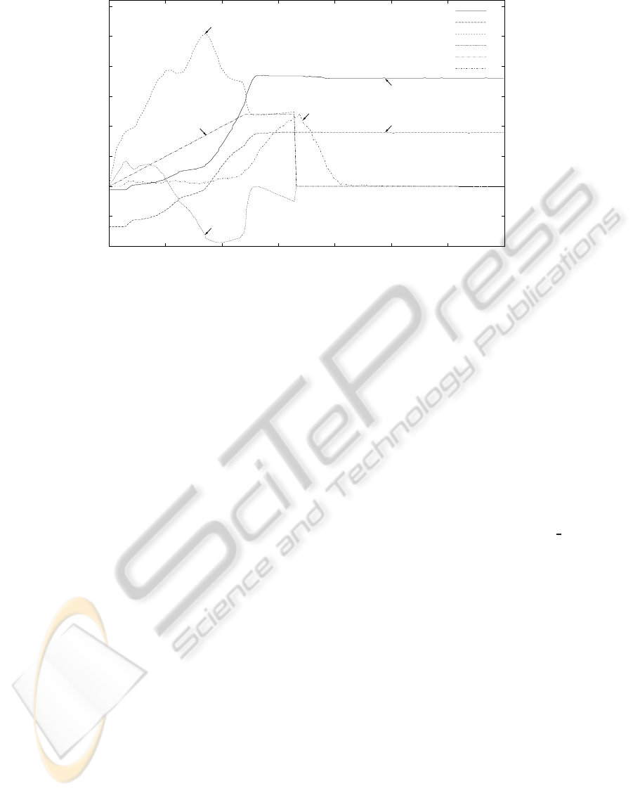
The adjustment of giving steering commands by
the pure castor controller is demonstrated by Figure
8. The diagram shows a left-turn of the wheelchair
starting with castor wheels in a blocking state using
the castor controller. It compares the given steering
command (5) from the user and the motor commands
for steering (3) and forward motion (4) computed by
the controller. The forward motor command is the
mean value of left and right motor command, and
the steering motor command the difference between
them. The controller uses the driving command and
the castor angles of the left (1) and right (2) wheels
as input values. It produces a peak for the left en-
gine of about 80% power (computed from forward
(3) and steering (4) motor command), and will be re-
duced when the castor wheels start to swivel. The
wheelchair starts to turn around significantly after the
peak is reached, as indicated by curve (6) measured by
the odometry of the wheelchair. The castor controller
reacts much earlier than an odometry based controller
and releases the user from doing this manually.
5 RELATED APPROACHES
An alternative approach is to turn the castor wheels
using an additional actuator, as for the Toyota PM re-
search vehicle (Toyota Motor Sales USA, 2009; Bon-
sor, 2004). The trail of the castor wheel can then
be 0, which makes it 180
◦
rotation symmetric. The
wheelchair manufacturer Otto Bock recently pre-
sented the XENO wheelchair with a steering system
called S
3
(Single Servo Steering, (Otto Bock Health-
Care GmbH, 2010)) in combination with a differen-
tial drive using an approach similar to that of the PM
research vehicle. For the additional cost of the cas-
tor turn servo engines, the Otto Bock system releases
the differential drive from the burdon of castor turn
forces, but the time to turn the front wheels can be
significantly longer than the time needed to turn clas-
sical castor wheels. This can confuse a user who is
unaware of this fact.
ICINCO 2010 - 7th International Conference on Informatics in Control, Automation and Robotics
178
-1
-0.5
0
0.5
1
1.5
2
2.5
3
0 1000 2000 3000 4000 5000 6000 7000
-200
-100
0
100
200
300
400
500
600
rad/s or rad
mm/s
time in ms
(3) 80% power
(1)
(2)
(4)
(5)
(6)
(1) castor left angle (rad)
(2) castor right angle (rad)
(3) steering motor command (rad/s)
(4) forward motor command (mm/s)
(5) steering input command (rad/s)
(6) wheelchair rotation speed (rad/s)
Figure 8: Castor controller for a left turn with blocking castor wheels.
6 CONCLUSIONS
In this paper we presented a castor wheel controller
for differential drive wheelchairswith two front castor
wheels (e.g., ROLLAND based on a Meyra wheelchair
of type CHAMP). The controller uses the devel-
oped kinematic model to project turn forces of castor
wheels to engine torques of differential drivevehicles.
Some test data were given to compare the steering be-
haviour with and without the controller. The major
benefit of the castor wheel controller is to release the
user from the task to compensatethe castor turn forces
using the joystick to simplify the driving with the joy-
stick.
One future work is to do more experimental eval-
uation and performance analysis of the pure and com-
bined castor wheel controllers before carrying out real
user studies. Moreover, the measurement of castor an-
gles through potentiometers is unprecise in a certain
range of angles. We will replace them by magnetic
angle measurement sensors for full coverage.
REFERENCES
Bonsor, K. (2004). How the Toyota PM works. Technical
report, Toyota Motor Sales, U.S.A., Inc,.
Brearley, M. N. (2009). Investigation of castor-wheel
shimmy. Journal of Mechanics and Applied Mathe-
matics, 33(4):491–505.
de Falco, D., Massa, G. D., and Pagano, S. (2009). On
the castor dynamic behavior. Journal of The Franklin
Institute, to appear.
Kauzlarich, J. J. P., Bruning, T. E., and Thacker, J. G. P.
(1984). Wheelchair caster shimmy and turning re-
sistance. Rehabilitation Research and Development,
20(2):15–29.
Kauzlarich, J. J. P., Bruning III, T. E., and Thacker, J. G. P.
(2000). Wheelchair caster shimmy II: Damping. Re-
habilitation Research and Development, 37(3):305–
313.
Lankenau, A. and R¨ofer, T. (2001). A safe and versatile mo-
bility assistant. IEEE Robotics and Automation Mag-
azine, 1(7):29–37.
Meyra Ortopedia (2010). Electric-wheelchairs CHAMP
1.594. http://www.meyra.de/meyraweb/o
basis.pl.
Otto Bock HealthCare GmbH (2010). XENO - stand up
and go! http://www.ottobock.com/.
Toyota Motor Sales USA (2009). The personal mo-
bility vehicle. http://www.toyota.com/concept-
vehicles/pm.html.
A CASTOR WHEEL CONTROLLER FOR DIFFERENTIAL DRIVE WHEELCHAIRS
179
