ON REAL-TIME WHOLE-BODY HUMAN TO HUMANOID MOTION
TRANSFER
Francisco-Javier Montecillo-Puente, Manish N. Sreenivasa and Jean-Paul Laumond
CNRS, LAAS, 7 avenue du colonel Roche, F-31077 Toulouse, France
Universit
´
e de Toulouse, UPS, INSA, INP, ISAE, LAAS, F-31077 Toulouse, France
Keywords:
Humanoids, HRP2, Human motion, Inverse kinematics, Neuroscience.
Abstract:
We present a framework for online imitation of human motion by the humanoid robot HRP-2. We introduce a
representation of human motion, the Humanoid-Normalized model, and a Center of Mass (CoM) anticipation
model to prepare the robot in case the human lifts his/her foot. Our proposed motion representation codifies
operational space and geometric information. Whole body robot motion is computed using a task-based prior-
itized inverse kinematics solver. By setting the human motion model as the target, and giving the maintenance
of robot CoM a high priority, we can achieve a large range of motion imitation. We present two scenarios
of motion imitation, first where the humanoid mimics a dancing motion of the human, and second where it
balances on one foot. Our results show that we can effectively transfer a large range of motion from the human
to the humanoid. We also evaluate the tracking errors between the original and imitated motion, and consider
the restrictions on the range of transferable human motions using this approach.
1 INTRODUCTION
Since the inception of humanoid robots several ap-
proaches have been developed, aiming at enabling au-
tonomous and intelligent behavior of the robot. The
general goal behind this idea is to develop humanoids
that, in the natural environment of the humans and
being among humans, can exhibit complex behavior.
The humanoid and the human share a common an-
thropomorphic structure, and recent studies have ex-
ploited this to directly transfer motion from humans to
humanoids. However, several obstacles imped the di-
rect transfer of motion like technological incompati-
bility of the humanoid robot, fragility, slow (relative
to human) motion speed, as well as a limited range of
motion.
There are several ways to approach the motion
transfer problem. In computer graphics, studies have
looked at “motion retargeting”, where human motion
is transferred from one virtual actor to another (Mul-
ton et al., 2008)(Chois and Ko, 2000). Machine learn-
ing approaches have also been developed to gener-
ate humanoid motion by observing and learning from
a human teacher (Schaal et al., 2003) (Shon et al.,
2005) (Takano et al., 2007). Another method is to
optimize the recorded human motion while consid-
ering humanoid kinematics and dynamics (Suleiman
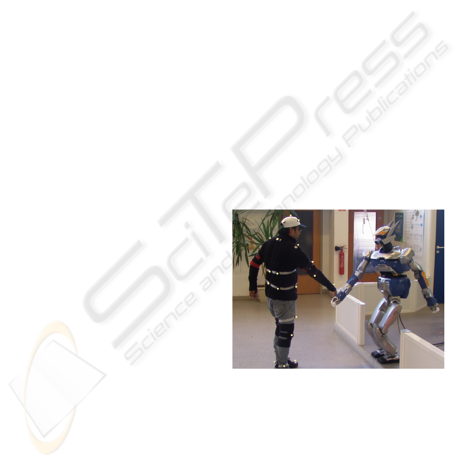
Figure 1: Picture of a human performer extending a hand-
shake and the humanoid robot HRP-2 imitating the gesture.
HRP-2 is a 30 Dof, 58 kg, 1.54 m tall humanoid robot man-
ufactured by Kawada Industries, Japan. The human motion
was tracked using reflective motion markers and transferred
in real-time to the humanoid.
et al., 2008) (Ruchanurucks et al., 2006). For our
purpose we broadly classify motion imitation studies
into offline and online methods. Offline methods have
the advantage of having ample processing time and
hence the human motion can be modified to fit the
humanoid’s limitations. While this allows for gen-
22
Montecillo-Puente F., N. Sreenivasa M. and Laumond J. (2010).
ON REAL-TIME WHOLE-BODY HUMAN TO HUMANOID MOTION TRANSFER.
In Proceedings of the 7th International Conference on Informatics in Control, Automation and Robotics, pages 22-31
DOI: 10.5220/0002915300220031
Copyright
c
SciTePress
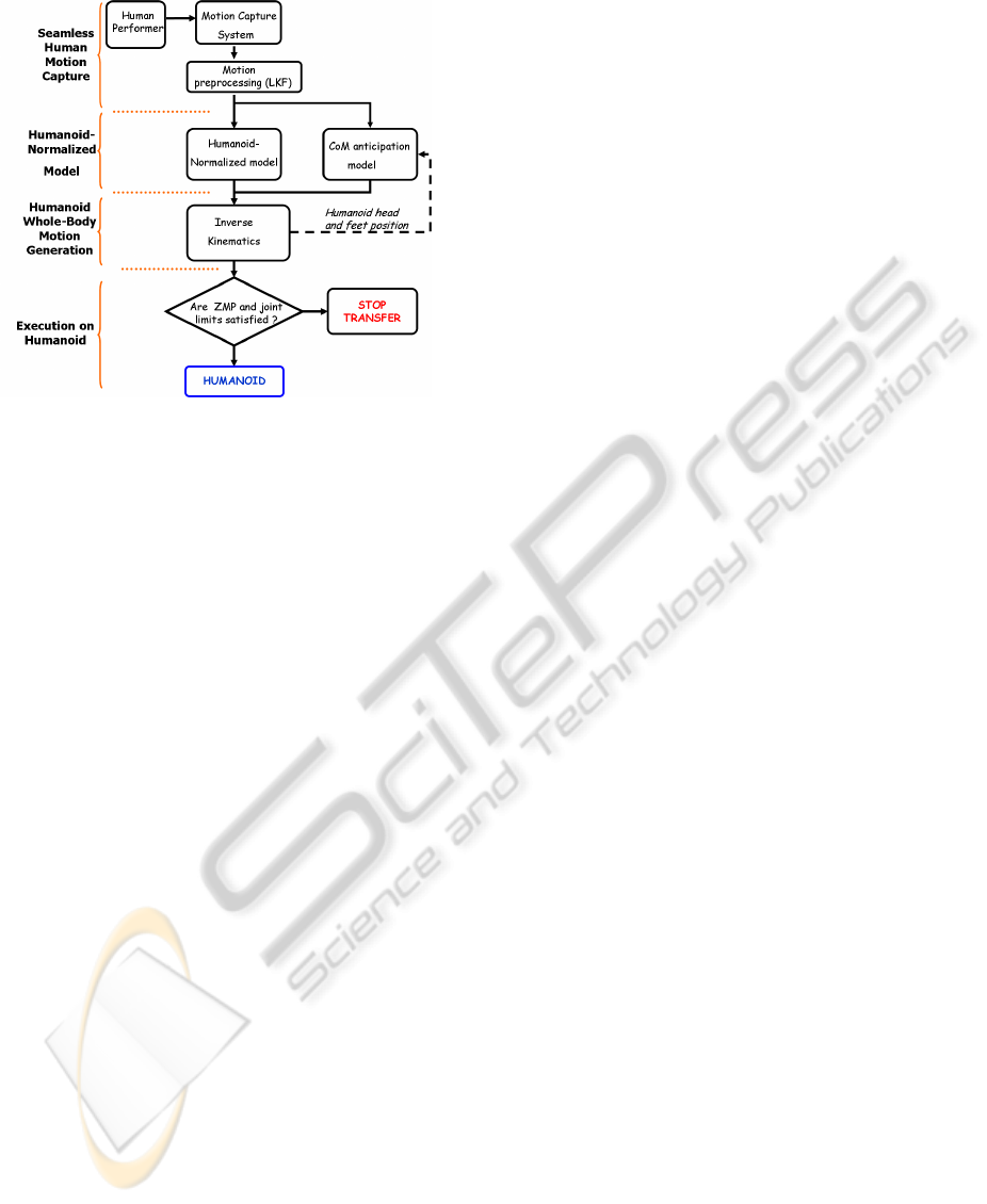
Figure 2: Organization of the algorithm to enable real-time
motion transfer from the human performer to the humanoid
robot.
eration of smooth and optimized motion of the hu-
manoid, these solutions can rarely be applied to on-
line motion transfer, often due to computational de-
lays during the optimization stage. Thus, online trans-
fer of human motion to a humanoid robot provides a
very different set of challenges compared to its offline
counterpart, and has been the focus of recent research
(Dariush et al., 2008a) (Dariush et al., 2008b) (Ya-
mane and Hodgins, 2009).
We explore this aspect of real-time human-
humanoid motion transfer by developing a framework
that allows us to transfer a large range of human mo-
tions to the humanoid, including balancing on one
foot. The challenges in this task include reliably
recording human motion, morphing the human data
such that it can be applied on a humanoid of a differ-
ent size and joint structure, and, generating the result-
ing humanoid motion in real-time while maintaining
balance.
1.1 Literature Review
1.1.1 Offline Motion Transfer
First we examine the work by Nakaoka et. al in
2005 (Nakaoka et al., 2005a), that enabled the hu-
manoid robot HRP2 to execute the famous and vi-
sually striking, traditional Aizu-Bandaisan Japanese
dance. Upper body motion for the HRP1s robot was
generated using motion capture markers on human
dancers and inverse kinematics. The leg motion of the
dancers was analyzed and extracted as motion prim-
itives (Nakaoka et al., 2005b). The upper and lower
body motions were then coupled and modified such
that the robot motion satisfied the dynamic stability
criteria, the Zero Moment Point (ZMP) (Vukobra-
tovic and Stepanenko, 1972). This method was imple-
mented offline and required several runs of the analyt-
ical process to reach a viable solution. However, this
method is not be easily applicable to a range of mo-
tions due to the extensive tuning and re-calculation re-
quired. As a more general framework, Ude et. al pro-
posed to solve a large scale optimization problem to
generate joint trajectories for a DB robot (Ude et al.,
2004). Joint angle trajectories of human motion were
computed by embedding a scalable kinematic struc-
ture to the human body motion. This was also solved
as an offline process because of the optimization com-
putational load. Robot balance was not taken into
consideration.
In the study by Ruchanurucks et al. (Ruchanu-
rucks et al., 2006), a non-linear optimization process
was solved subject to joint limits, autocollision, ve-
locity limits and force limits constraints. To increase
the convergence speed they parametrized the motion
by B-splines. In Suleiman et. al (Suleiman et al.,
2008), first the joint motion data was scaled into the
humanoid robot’s joints. Then, an optimization prob-
lem was solved to fit this motion to the robot structure
and its physical limits, keeping in mind the analyti-
cal gradient of the dynamic model. Among other ap-
proaches, studies have also used machine learning al-
gorithms to imitate human motion (Shon et al., 2005).
The idea here was to generate a low dimensional la-
tent space to map a model variable from the robot
motion to human motion, and vice-versa. In order
to generate the final stable motion, extensive training
was required using pairs of human and robot motion.
In most of these studies the humanoid is con-
strained to maintain both its feet on the ground. Even
in the approaches that allowed feet motion, for exam-
ple (Suleiman et al., 2008) and (Ruchanurucks et al.,
2006), the timing of the foot lift-off has to be prede-
fined which results in a rigid range of motion.
1.1.2 Online Methods
In the context of online transfer of human motion to
humanoid robots or even virtual avatars in animation,
the means used to capture human motion plays a very
important role. One way is the use of motion capture
technology. These systems represent human motion
by directly tracking the position of infra-red markers
attached to the human body or attaching a skeleton
to these markers. However, some recent studies have
also implemented markerless tracking where human
motion is reconstructed by using video cameras.
First, we consider the study by Dariush et al. (Dar-
iush et al., 2008b), where the authors developed a
ON REAL-TIME WHOLE-BODY HUMAN TO HUMANOID MOTION TRANSFER
23

methodology to retarget human motion data to the hu-
manoid robot ASIMO. Human motion was captured
using a markerless pose tracking system. Here upper
body motion was considered by mapping the carte-
sian positions of the waist, wrists, elbows, shoulder
and neck. The corresponding joint motion on the
humanoid was calculated using inverse kinematics,
while respecting the individual joint limits. In this
case, a seperate balance controller was used to move
the legs in order to compensate for the retargeted mo-
tion of the upper body. In a later study, the authors
used a learning approach to pre-generate knowledge
about a number of human postures (Dariush et al.,
2008a). During the actual motion retargeting, head
and torso motion was monitored and the template
closest from the ones learned was assigned. The arms
were analyzed as 3D blobs and their position esti-
mated. From this data the 3D features for head, shoul-
der, waist, elbows and wrists were localized. Using
inverse kinematics and the balance controller, the mo-
tion was then played on the humanoid robot.
Using a different approach, Yamane et al. (Ya-
mane and Hodgins, 2009), simultaneously tracked
motion capture data using a balance controller and a
tracking controller. Tha balance controller was a lin-
ear quadratic regulator designed for an inverted pen-
dulum model. The tracking controller computed joint
torques to minimize the difference from the desired
human capture data while considering full-body dy-
namics. The resulting motion was retargeted on the
humanoid in simulation.
1.2 Our Contribution
We present an alternative way to transfer human
motion data to our humanoid robot HRP2.
• Taking inspiration from computer animation
studies we extended the idea of the normalized
skeleton (Multon et al., 2008) and developed a
“Humanoid-Normalized model” on which filtered
motion capture data can be retargeted online. To
do this we first devise a method to reliably record
human motion by using Kalman filters to fill gaps
(due to occlusions) in capture data. Rather than
directly using cartesian positions like in (Dariush
et al., 2008a) (Dariush et al., 2008b), or joint angles
(Yamane and Hodgins, 2009), we also encode the
orientation of the postures by attaching virtual planes
to sets of human motion marker points. These virtual
planes define the orientation of the important joints in
the human, like the head, chest, arms and waist. We
propose a Humanoid-Normalized model that consists
of a combination of the positions of the extremities
and the normals to the virtual planes. The motion of
this model is used to drive the humanoid robot via a
task based inverse kinematics solver.
• In order to achieve single foot support phases
we also introduce the original idea of an anticipation
model, motivated by results in human neuroscience.
This model serves the purpose of preparing the
humanoid to stand on one foot by taking into ac-
count previous motion of the human head, and the
humanoid’s Center of Mass (CoM). Figure 2 shows
the organization of the overall algorithm.
We evaluate the results from our experiments and
compare them to those reported in literature. In the
following sections we describe in detail 1) The cap-
ture of human motion capture data, 2) Application to
the Humanoid-Normalized model, 3) Generating hu-
manoid motion using inverse kinematics 4) The CoM
Anticipation model 5) Experiments on our humanoid
robot, HRP2 and finally 6) Discussion of our results
as well as future perspectives.
2 SEAMLESS HUMAN MOTION
CAPTURE
Human motion was recorded in a tracking hall
equipped with 10 infra-red tracking cameras (Mo-
tionAnalysis, CA, USA). The system is capable of
tracking the position of markers within a 5x5 m space
within an accuracy of 1mm, at a data rate of 100 Hz.
The human to be tracked wore 41 reflective mark-
ers firmly attached to their body using velcro straps,
or tape (see Figure 1 and 3). In some cases there
was the possibility of loss of marker data due to self-
occlusions. This is very detrimental to the imitation
algorithm since the humanoid model depends on con-
tinous human motion data. To solve this, we imple-
mented a linear Kalman filter that estimates the posi-
tion of markers that are lost for short durations of time
(less than 0.5 seconds). If a marker is lost for periods
longer than 0.5 seconds, we assume the model to be
unrecoverable and initiate an emergency stop. The la-
tency between capture of marker data and the kalman
filtered data is about 30 ms. This filtered data is then
applied to the Humanoid-Normalized model.
ICINCO 2010 - 7th International Conference on Informatics in Control, Automation and Robotics
24
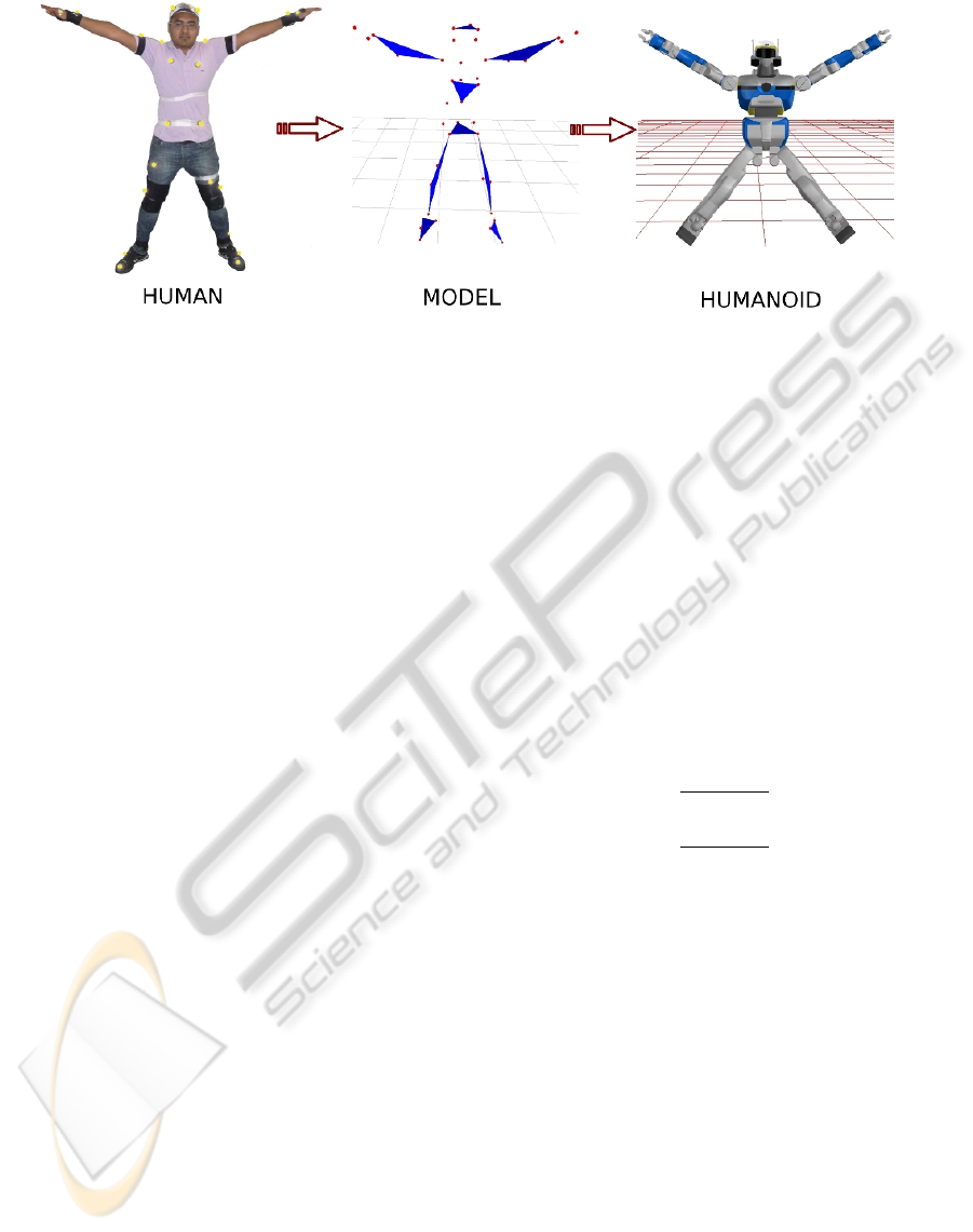
Figure 3: Human→Humanoid Normalized Model→Humanoid. Motion capture position data from the human is transferred
to the normalized model and associated with the planes and humanoid joints. The motion of these planes and joints drives the
humanoid motion.
3 HUMANOID-NORMALIZED
MODEL
3.1 Why a Normalized Model?
Multon et al. (Multon et al., 2008) proposed the use
of a normalized skeleton, which acts as an intermedi-
ate entity to map motion between two different dig-
ital actors. The generation and adaptation of motion
was done by assuming that there exists planes formed
by the arms and legs. The normalized skeleton was
represented by normalized segments, limbs of vari-
able lengths and the spine. Humans come in dif-
ferent sizes and shapes, and most adults are bigger
than our humanoid HRP2. HRP2 also has two addi-
tional DoF’s in its chest (pitch and yaw) and this re-
quires special treatment unlike that for the humanoid
ASIMO, used in (Dariush et al., 2008a), where the
torso is one single joint. There is thus a need to extract
the relevant characteristics of human motion, and de-
fine it in a form that is suitable for application on hu-
manoids. We extended the idea presented by Multon
and colleagues by defining planes for not only the
arms, but also the head, chest and waist. The planes
are attached to the human body in such a way that they
can be directly used to define geometric tasks in the
prioritized inverse kinematics solver. A combination
of the orientation of these planes, and the position of
the extremities (head and wrists) form the Humanoid-
Normalized model (henceforth HN Model).
3.2 Components of
Humanoid-normalized Model
The physical model of the upper body was built from
the cartesian positions of 22 markers on the human
Figure 3. Before the model is computed we scale the
marker positions according to a modified version of a
standard scaling algorithm (Boulic et al., 2009). First,
we start with the head. Three markers on the head
were used to form the head virtual plane. The center
of these markers were considered in the HN model.
The normal to the plane defined by these markers was
computed. In the HN model we represent the orienta-
tion of the head as the orthogonal to this normal vec-
tor. For the head, the plane normal is computed as,
N
head
= V
0
×V
1
(1)
where,
V
0
=
p
0
− p
1
||p
0
− p
1
||
V
1
=
p
0
− p
2
||p
0
− p
2
||
p
0
, p
1
, p
2
are the markers associated to the head vir-
tual plane.
Similarly, chest and waist virtual planes were con-
structed using the relevant markers such that their nor-
mals were approximately in the sagittal direction (see
Figure 3 for illustration of markers used). Virtual
planes for the arms were constructed using markers
on the shoulder, elbow and wrist. Instead of using
the positions of all these markers, the arm posture is
represented by the normal to this plane and the wrist
position. We chose this representation because of the
difficulty to directly map the cartesian position of all
these markers to the robot structure. In addition to up-
per body characteristics, we also included the position
of the feet in the HN model.
Thus, overall the Humanoid-Normalized model is
expressed by the following set of geometric proper-
ties:
[P
h
,V
h
, N
c
,V
w
, P
lh
, N
la
, P
rh
, N
ra
, P
l f
, P
r f
] (2)
ON REAL-TIME WHOLE-BODY HUMAN TO HUMANOID MOTION TRANSFER
25

where P
h
is a point representing the position of the
head, V
h
is a vector representing the orientation of the
head, N
c
is a vector representing the normal of the
chest plane, V
w
is a vector representing the orientation
of the waist, P
lh
is a point representing the position of
the left hand, N
la
is a vector representing the normal
to the left arm plane, P
rh
is a point representing the
position of the right hand, N
ra
is a vector representing
the normal to the right arm plane, P
l f
is a point rep-
resenting the position of the left foot, P
r f
is a point
representing the position of the right foot.
4 HUMANOID INVERSE
KINEMATICS
The HN model explained in the previous section al-
lows us to retarget human motion into a form suit-
able for transfer onto the humanoid. To generate mo-
tion of the humanoid we used a task-based inverse
kinematics solver (Nakamura, 1991).
4.1 Prioritized Inverse Kinematics
Forward kinematics expresses the relationship be-
tween the variation of the joint parameters δq and
the corresponding displacement δx in the operational
space (Nakamura, 1991). This is given by,
δx = Jδq (3)
where J is the m × n jacobian matrix, m being the di-
mension of the task, and, n is the number of degrees
of freedom. The inverse kinematics model determines
the joint variation that produces an expected displace-
ment, which is obtained by solving the system in Eq.
3. However, for the humanoid robot we have m < n,
thus this linear system is under-constrained. In this
case, all the solutions of the system can be written as:
δq = J
#
δq + (I − J
#
J)z (4)
where J
#
= J
T
(JJ
T
)
−1
is the pseudo inverse of J, I
is the n× n identity matrix, (I −J
#
J) is the null-space
projector of J, and z is an n-dimensional arbitrary vec-
tor. The first term on the right side of equation 4 is a
generic solution and z in the second term can be used
to satisfy additional constraints without modifying δx.
The generic expressions for solving n tasks with
descending order of priorities are (Siciliano and Slo-
tine, 1991):
N
0
= I
ˆ
J
i
= J
i
N
i−1
N
i
= I −
ˆ
J
#
i
ˆ
J
i
δq
i+1
=
ˆ
J
#
i+1
(δx
i+1
− J
i+1
δq
i
)
where N
i
is the projector associated with the i
th
task,
J
i
is the jacobian of the i
th
task, I is the n × n identity
matrix. The update δq
i
is iteratively computed for all
tasks.
4.2 Whole-body Motion Generation
The position for each joint is generated from a prior-
itized stack of tasks (Yoshida et al., 2006), which is
solved using the inverse kinematics formulation ex-
pressed above. Each property of the HN model repre-
sentation is used as the target input for the tasks. Our
task stack was defined as (in decreasing priority):
1. Homogenous transformation task for each feet,
i.e. both position and orientation are fixed,
2. Position task for Center of Mass (CoM) projection
(X and Y positions),
3. Position task for the head,
4. Homogenous transformation task for the left
wrist,
5. Homogenous transformation task for the right
wrist,
6. Orientation vector task for the chest,
7. Orientation vector task for the waist,
8. Orientation vector task for the head.
We use four kinds of tasks: position task, orienta-
tion vector task, homogenous transformation task and
a CoM task. As examples, we define in more detail
the task construction for the head and the arms. The
CoM task is detailed in the next section. The position
task of the head f
h
(θ) is defined as,
f
h
(θ) = P
t
h
− P
h
(θ)
where P
t
h
is the target of the task given by the position
of the head in the HN model representation. P
h
(θ)
is the position of the humanoid head expressed as a
function of the robot dof’s θ.
For the orientation vector task of the head f
h
(θ)
we have
f
h
(θ) = V
t
h
×V
h
(θ) (5)
where V
t
h
is the target head direction, which is given
by the head orientation vector in the HN model. And
V
h
(θ) is the corresponding vector of the humanoid
head, as a function of the robot dof’s θ. The orien-
tation vector tasks for the chest and waist are defined
in a similar way.
For each arm a homogeneous transformation task
is constructed for the wrist joint. The target trans-
formation is constructed from two properties, wrists
ICINCO 2010 - 7th International Conference on Informatics in Control, Automation and Robotics
26
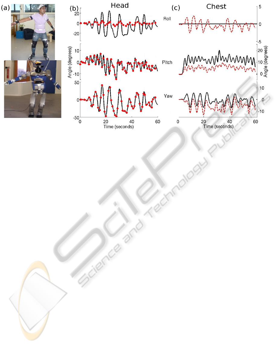
Figure 4: Scenario 1. (a) Snapshot of human dancing and its imitation by HRP2 (b) Roll, pitch and yaw angles of the head
joint during the dancing motion. Solid black line indicates the angles of the HN model, this was the target the humanoid had
to follow. Red circles indicate the corresponding angular value on HRP2 (c) Chest angles of the HN model (solid black line)
and the corresponding angles on the humanoid (dashed red line).
position and the normal to the HN model’s arm plane.
The target rotation matrix in the homogenous trans-
formation is computed as,
R
t
= [N
arm
×V N
arm
V ] (6)
where N
arm
is the normal of the left or right arm plane,
and V is a unit vector connecting the elbow and wrist
markers. It should be noted that the N
arm
is parallel to
the axes of the humanoid elbow joint.
5 COM ANTICIPATION MODEL
The CoM of a humanoid robot is a vital indicator to
its stability. In order to remain statically stable, the
projection of CoM on the floor should remain within
the support polygon defined by the two feet of the hu-
manoid. If the human performer were to lift his/her
foot, the CoM of the humanoid robot would have to
be shifted in advance towards the other foot in order
to maintain balance. In order to know when this shift
is required, we take inspiration from results in human
neuroscience research. Studies have reported strate-
gies by which motion of the CoM in humans can be
related to foot placement and hip orientation (Patla
et al., 1999), (Vallis and McFadyen, 2005).
To manipulate the projection of the humanoid
CoM on the floor we constrain it to track a target. The
target position is computed depending on the current
stance of the HN model, i.e. Double Support (DS)
or Single Support (SS). The transition of stance from
single to double support is detected using the position
and velocity of the feet. When either of these mea-
sures exceed a pre-determined threshold a change of
stance is said to have occured. For the motion of the
CoM the target is computed as:
CoM
i
=
CoM
i−1
+ α(V
head
·V
f eet
)V
f eet
if DS
p
f oot
+ βV
head
if SS
(7)
where,
CoM
i
= CoM X and Y positions at time step i,
V
head
= HN Model head 2D velocity vector,
V
f eet
= Unity vector across robot’s feet,
p
f oot
= Humanoid support foot X and Y positions,
α, β are constants.
6 IMPLEMENTATION OF
ONLINE HUMAN-HUMANOID
MOTION TRANSFER
Our framework was implemented using the software
achitecture Genom, (Fleury et al., 1997). Mainly, we
have four modules to establish communication from
the motion capture system to the HRP2 robot inter-
face. First, we have a motion capture server whose
function is to send motion data to the network via
UDP protocol. These data are filtered as described
ON REAL-TIME WHOLE-BODY HUMAN TO HUMANOID MOTION TRANSFER
27
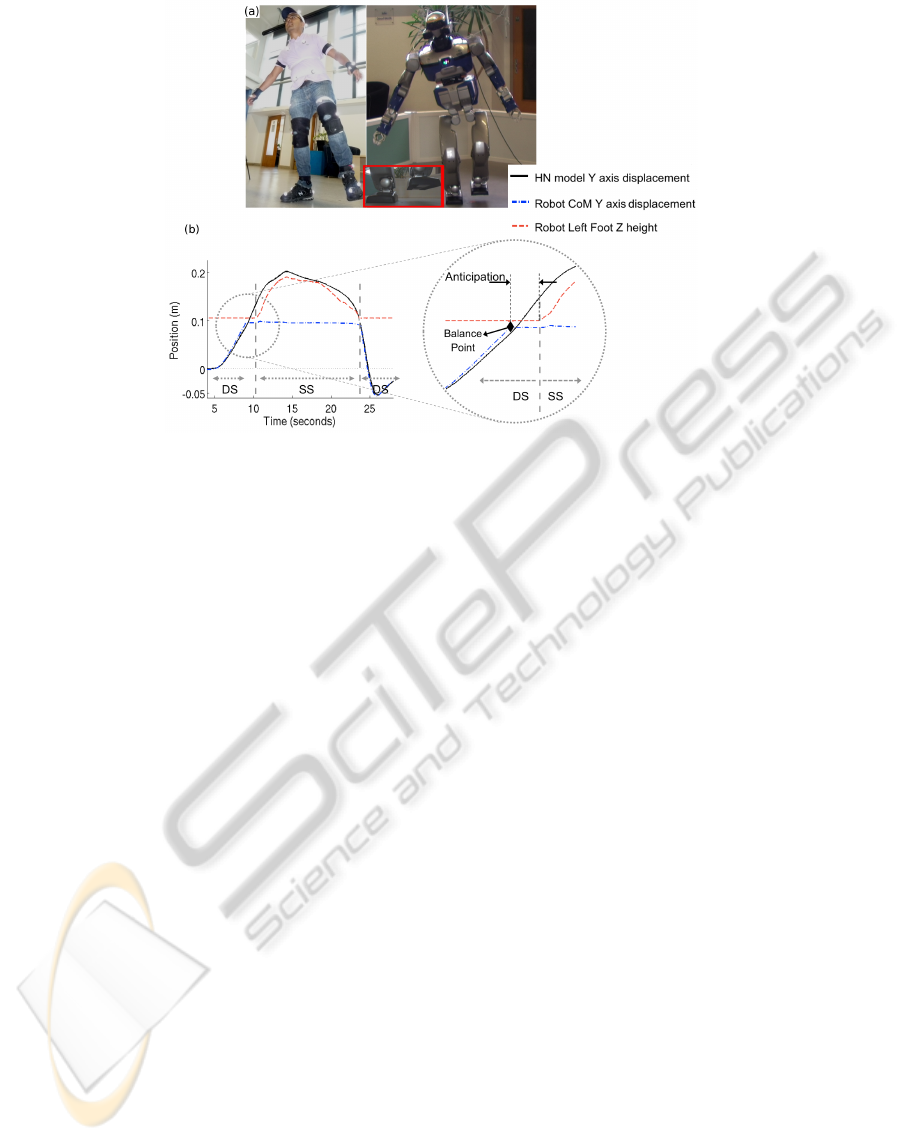
Figure 5: Scenario 2. (a) Picture of humanoid imitating the human lifting his foot. (b) Sideways displacement of the HN
model head (solid black line), and the vertical height of the humanoid’s lifting foot (dashed red line). Also shown is the Y
displacement of the humanoid’s CoM (dash-dot blue line). Zoom inset shows a magnified view of the anticipation phase. The
anticipation occurs between the ’Balance point’ and the time when the humanoid lifts its foot.
in section 2. A second Genom module reads the
seamless motion data and computes the robot mo-
tion. This module implements the HN-normalized
model, the CoM anticipation model and the priori-
tized inverse kinematics solver. Finally, via a plugin
we send robot motion data from the motion gener-
ation Genom-module to the HRP2 interface control
panel.
We present two scenarios that illustrate the
capabilities of our algorithm. In the first scenario
we assume the robot’s feet to be fixed and imitate
the motion of a human performer executing a slow
dance with the upper body, including bending of the
knees and ankles. In the second scenario, the robot
is allowed to lift-off with one of its feet and balance
on the other foot. This was chosen to illustrate the
anticipation model which prepares the humanoid
for balancing on one foot. The parameters used for
the CoM anticipation model were, α = 0.12, β =
0.01. All computations were run on an Intel Core 2
CPU 6400 @2.13GHz, with 2GB of RAM memory.
At each solution step we required ∼30 ms to build
the Humanoid-Normalized model and to solve the
stack of tasks using a damped inverse kinematics
solver. The video of the results can be accessed at
http://homepages.laas.fr/manu/videos/motionImitation.mp4
6.1 Dancing
The human performer was asked to perform a simple
dance without stepping or sliding his feet. Figure 4-a
shows the posture of the human and the humanoid in
the middle of the dance. The motion computed by the
algorithm was smooth, without joint position or ve-
locity limit violations, and was quasi-statically stable.
Figure 4-b & c show the roll, pitch and yaw angles of
the head and chest of the HN model and those of the
humanoid robot. Despite the low priority given to the
head orientation task, we see that the yaw and pitch
angles were matched very closely, while roll angle of
the humanoid was much lesser than the HN model.
This was because the yaw and pitch axis are directly
available on HRP2 (independent of the other joints),
however, the humanoid does not have a roll axis for
the head joint. The roll variation seen in Figure 4-b
was due to the movement of the whole body. Chest
roll of the HN model was not considered, but to ac-
count for the movement of the rest of the body we
see an induced roll component on HRP2. The pitch
and yaw angles of the humanoid’s chest followed the
HN model less closely due to the lower priority of this
task. Since the arms and the head are connected to the
chest, and their respective tasks have a higher priority,
the chest joint has a reduced degree of mobility.
6.2 Foot Lift
In this scenario the human performer shifted his
weight onto one leg and maintained his balance for
a few seconds before slowly returning to rest on both
feet. Figure 5-a shows the human and the humanoid
balancing on one foot (SS stance). The motion of the
ICINCO 2010 - 7th International Conference on Informatics in Control, Automation and Robotics
28

Table 1: Mean RMS error between HN model and hu-
manoid. Values in brackets denote the mean RMS error in
X,Y and Z positions for wrist positions, and roll (R), pitch
(P) and yaw (Y) for head, chest and waist orientations.
Property Mean RMS Mean RMS
position (m) orientation (deg)
CoM ∼ 0 -
Head ∼ 0 4.09
(R: 11.8 P: 0.22 Y: 0.26)
Left wrist 0.02 -
(X: 0.013 Y: 0.02 Z: 0.3)
Right wrist 0.05 -
(X:0.05 Y:0.017 Z: 0.08)
Chest - 4.2
(R: 1.1 P: 6.7 Y: 4.8)
Waist - 6.4
(R: 1.1 P: 4.62 Y: 0.52)
head in the HN model, and the vertical position of
the foot of the humanoid is plotted in Figure 5-b. We
observe that the head shifts towards the support foot
(right foot) before the lifting the other foot (Figure
5-b). The sideways displacement of the head reaches
the Y position of the support foot about 1s before foot
lift. Before reaching this point, the CoM projection
was derived according to Eq. 7 (DS stance). Once
the head reaches the support foot, the CoM is main-
tained at this position (referred to as “Balance Point”
in Figure 5-b). After this point, the behavior of the
CoM is dictated by a different relation (SS stance in
Eq. 7). It should be noted that for slow head motion,
the projection of the CoM and the head position co-
incide (a small offset can be seen in the zoom inset
in Figure 5-b)).
7 DISCUSSION
Among studies that have looked at human-humanoid
motion retargeting it is generally difficult to define a
single metric reflecting the quality of motion trans-
fer. This can be because of several reasons. The
physical structure of humanoids can vary quite sig-
nificantly (size, number of DoFs, range of motion
etc). Moreover, defining a mathematical term to the
rather abstract idea of “good” motion imitation is not
clear. Dariush and colleagues, formulated a measure
for “tracking error” to express the effectiveness of
their algorithm. We employ a similar strategy and ad-
ditionally investigate the limitations of our approach
vis-
`
a-vis dynamic stability of the humanoid.
7.1 Quality of Motion Imitation
Quality of motion imitation was quantified by mea-
suring the root mean square error between the target
(HN model) and the humanoid robot. Table 1 lists
the relevant parameters and the errors. The position
of the CoM and head were tracked almost prefectly.
This was because both these tasks had a very high
priority. Comparitively, head orientation which had
a lower priority had a mean error of 4 deg. But it
should be noted that most of this error was because of
the roll angle (HRP2 does not have a head roll axis).
The right wrist position error was slightly larger that
the left wrist. This can be attributed to the fact that
left wrist task came before the right wrist task in the
priority list. Thus, once the left wrist position and
orientation was fixed, it became more difficult for the
right wrist to reach exactly its target transformation.
Comparing across studies, Dariush et al. 2008b, re-
ported an error of about 0.02 m in tracking the wrist
position while assigning them to a “medium priority
group”. In our case the head was the highest prior-
ity, and hence a low error, while the hands were low
priority, hence the larger error. Chest and waist orien-
tation were lower in the priority list and hence show
larger errors in orientation than the other joints. Over-
all, these results show that we were able to retarget a
large part of the motion of the human onto the hu-
manoid.
7.2 Limitations
We analysed the limitations of our imitation sys-
tem, and those of our humanoid, by setting up the
following test. We attached the marker set on the
performer and he was asked to move his right hand
in an up-and-down motion at different speeds. After
transferring the motion to the humanoid, we observed
the shift of the Zero Moment Point (ZMP) of the hu-
manoid for the different human hand speeds. For the
up and down motion, we detect the maximum and
minimum values of the ZMP components, and check
if it is inside the supporting polygon. We found that
the humanoid became unstable when the hand speed
was higher than 1 m/s (Figure 6). This example illus-
trates the limitations of using inverse kinematics with-
out considering, simultaneously, the dynamic stability
of the humanoid. To truly imitate both the kinematics
and dynamics of the human motion, it would be im-
portant to take both of these into account during the
modeling stage itself. For example, using a dynami-
cal model (exact or simplified) at the motion planning
stage could be a useful in this regard.
Kanehiro et al. (Kanehiro et al., 2008b), devised a
ON REAL-TIME WHOLE-BODY HUMAN TO HUMANOID MOTION TRANSFER
29
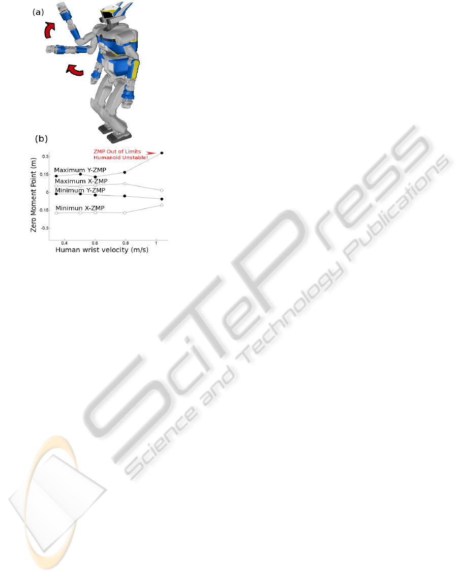
Figure 6: (a) Illustration of the hand up and down motion on
the simulated HRP2, (b)Plot of ZMP of the humanoid robot
vs. human hand velocities. Illustrated is the point at which
the humanoid becomes unstable because of excessive hand
speeds.
way to optimize quasi-static humanoid motion, such
that it can be performed faster, but also within the dy-
namic limits of the humanoid. We recorded the online
dancing motion of the humanoid, and optimized it of-
fline to see how much faster the same motion could
be played. We found that our original 60 seconds
of dancing motion could be optimized to 31 seconds
while respecting the kinematic and dynamic limits of
the humanoid HRP2. Thus, offline optimization could
serve as a benchmark in judging how effective and ro-
bust online motion retargeting algorithms really are.
Finally, one limitation of our formulation of the
HN model is that it cannot guarantee self-collison
avoidance on the humanoid. This could be included at
the inverse kinematics stage by defining self-collison
avoidance as a constraint (Dariush et al., 2008a) (Ka-
noun, 2009) (Kanehiro et al., 2008a).
8 SUMMARY AND FUTURE
PERSPECTIVES
In this study we have presented an online method
by which a humanoid robot can imitate human mo-
tion. The evaluation of the results show that the mo-
tion generated by the humanoid closely resembles the
original human motion. The proposed CoM antici-
pation model allows the humanoid to balance itself
on one foot taking the cue from the human. This
model inspired from neuroscience research opens up
new windows towards incorporating biological prin-
ciples in humanoid motion control (Berthoz, 2000),
(Sreenivasa et al., 2009). The use of the Humanoid-
Normalized model allows standardization across an-
thropomorphic figures irrespective of proportions (for
example marionettes). To further improve imitation it
could be interesting to consider the exact dynamics of
the humanoid, as well as self-collison avoidance, in
the motion planning algorithm. At the present state of
this work, we can say that our humanoid robot HRP-
2, is capable of mimicking Tai-chi like movements,
but not yet quite at the level of Karate.
ACKNOWLEDGEMENTS
F.J. Montecillo-Puente benefits of a Mexican
CONACyT, SEP grant. The authors would like to
thank Anthony Mallet, Tan Viet Anh Truong and
Oussama Kanoun for taking part in helpful discus-
sions and assisting with the experiments on HRP2
and motion capture. Part of this work is supported by
the French ANR Project Locanthrope.
REFERENCES
Berthoz, A. (2000). The brain’s sense of movement. Har-
vard University Press, Cambridge, MA.
Boulic, R., Maupu, D., and Thalmann, D. (2009). On scal-
ing strategies for the full body interaction with vir-
tual mannequins. Journal Interacting with Computers,
Special Issue on Enactive Interfaces, 21(1-2):11–25.
Chois, K. J. and Ko, H. S. (December 2000). Online motion
retargetting. The Journal of Visualization and Com-
puter Animation, 11(5):223–235.
Dariush, B., Gienger, M., Arumbakkam, A., Goerick, C.,
Zhu, Y., and Fujimura, K. (2008a). Online and mark-
erless motion retargeting with kinematic constraints.
In IEEE/RSJ International Conference on Intelligent
Robots and Systems, pages 191–198.
Dariush, B., Gienger, M., Jian, B., Goerick, C., and Fu-
jimura, K. (2008b). Whole body humanoid control
from human motion descriptors. In IEEE Interna-
tional Conference on Robotics and Automation, pages
2677–2684.
Fleury, S., Herrb, M., and Chatila, R. (1997). Genom: A
tool for the specification and the implementation of
operating modules in a distributed robot architecture.
In IEEE/RSJ International Conference on Intelligent
Robots and Systems, pages 842–848.
ICINCO 2010 - 7th International Conference on Informatics in Control, Automation and Robotics
30

Kanehiro, F., Lamiraux, F., Kanoun, O., Yoshida, E., and
Laumond, J.-P. (2008a). A local collision avoidance
method for non-strictly convex polyhedra. Robotics:
Science and Systems, IV.
Kanehiro, F., Suleiman, W., Lamiraux, F., Yoshida, E., and
Laumond, J.-P. (2008b). Integrating dynamics into
motion planning for humanoid robots. In IEEE/RSJ
International Conference on Intelligent Robots and
Systems, pages 660–667.
Kanoun, O. (2009). Task-driven motion control for hu-
manoid robots. PhD thesis, LAAS-CNRS; Universit
´
e
de Toulouse.
Multon, F., Kulpa, R., and Bideau, B. (2008). Mkm: A
global framework for animating humans in virtual re-
ality applications. Presence: Teleoper. Virtual Envi-
ron., 17(1):17–28.
Nakamura, Y. (1991). Advanced Robotics: Redundancy and
Optimization. Addison-Wesley Longman Publishing,
Boston.
Nakaoka, S., Nakazawa, A., Kanehiro, F., Kaneko, K.,
Morisawa, M., and Ikeuchi, K. (2005a). Task model
of lower body motion for a biped humanoid robot
to imitate human dances. In IEEE/RSJ International
Conference on Intelligent Robots and Systems, pages
3157–3162.
Nakaoka, S., Nakazawa, A., Kanehiro, F., Kaneko, K.,
Morisawa, M., and Ikeuchi, K. (2005b). Task model
of lower body motion for a biped humanoid robot
to imitate human dances. In IEEE/RSJ International
Conference on Intelligent Robots and Systems, pages
3157–3162.
Patla, A., Adkin, A., and Ballard, T. (1999). Online steer-
ing: coordination and control of body center of mass,
head and body reorientation. Experimental Brain Re-
search, 129(4):629–634.
Ruchanurucks, M., Nakaoka, S., Kudoh, S., and Ikeuchi,
K. (2006). Humanoid robot motion generation with
sequential physical constraints. In IEEE Interna-
tional Conference on Robotics and Automation,, pages
2649–2654.
Schaal, S., Ijspeert, A., and Billard, A. (2003). Com-
putational Approaches to Motor Learning by Imita-
tion. philosophical transactions: biological sciences,
358(1431):537–547. philosophical transactions: bio-
logical sciences (The Royal Society).
Shon, A., Grochow, K., and Rao, R. (2005). Robotic imita-
tion from human motion capture using gaussian pro-
cesses. In 5th IEEE-RAS International Conference on
Humanoid Robots.
Siciliano, B. and Slotine, J. (1991). A general frame-
work for managing multiple tasks in highly redundant
robotic systems. In IEEE Internatioal Conference on
Advanced Robotics, pages 1211–1216.
Sreenivasa, M.-N., Soueres, P., Laumond, J.-P., and
Berthoz, A. (2009). Steering a humanoid robot by its
head. In IEEE/RSJ International Conference on Intel-
ligent Robots and Systems.
Suleiman, W., Yoshida, E., Kanehiro, E., Laumond, J.-P.,
and Monin, A. (2008). On human motion imitation by
humanoid robot. In IEEE International Conference on
Robotics and Automation.
Takano, W., Yamane, K., and Nakamura, Y. (2007). Cap-
ture database through symbolization, recognition and
generation of motion patterns. In IEEE International
Conference on Robotics and Automation, pages 3092–
3097.
Ude, A., Atkeson, C., and M., R. (2004). Programming
full-body movements for humanoid robots by obser-
vation. In Robotics and Autonomous Systems, vol-
ume 47, pages 93–108.
Vallis, L. and McFadyen, B. (2005). Children use different
anticipatory control strategies than adults to circum-
vent an obstacle in the travel path. Experimental Brain
Research, 167(1):119–127.
Vukobratovic, M. and Stepanenko, J. (1972). On the stabil-
ity of anthropomorphic systems. Mathematical Bio-
sciences, 15:1–37.
Yamane, K. and Hodgins, J. (2009). Simultaneous tracking
and balancing of humanoid robots for imitating hu-
man motion capture data. In IEEE/RSJ International
Conference on Intelligent Robots and Systems, pages
2510–2517.
Yoshida, E., Kanoun, O., Esteves, C., and Laumond, J.-
P. (2006). Task-driven support polygon humanoids.
In IEEE-RAS International Conference on Humanoid
Robots.
ON REAL-TIME WHOLE-BODY HUMAN TO HUMANOID MOTION TRANSFER
31
