
EXPERIMENTING WITH AUTONOMOUS CALIBRATION
OF A CAMERA RIG ON A VISION SENSOR NETWORK
Kyung min Han, Yuanqiang Dong and Guilherme DeSouza
Department of Electrical and Computer Engineering, University of Missouri
349 Engineering Building West, Columbia, U.S.A.
Keywords:
Vision sensor network, Image clustering, Global coordinate reference.
Abstract:
This paper presents a completely autonomous camera calibration framework for a vision sensor network con-
sisting of a large number of arbitrarily arranged cameras. In the proposed framework, a sequence of images for
calibration is collected without a tedious human intervention. Next, the system automatically extracts all nec-
essary features from the images and finds the best set of images that minimizes the error in 3D reconstruction
considering all cameras in the set.
1 INTRODUCTION
Calibration of multiple camera systems became an
important topic along with vision sensor networks
(VSN) such as for: virtual and augmented reality;
surveillance; battle field reconnaissance; etc. (Re-
magnino and Jones, 2002; Jaynes, 1999; Koller et al.,
1997). In order to calibrate a VSN several criti-
cal steps must be taken: 1) acquiring images syn-
chronously; 2) extracting feature points from the im-
ages; 3) establishing the correspondence among the
feature points in multiple images from multiple cam-
eras; 4) performing individual camera calibrations;
and 5) computing a global coordinate reference for
all cameras. Currently, a few of these steps still re-
quire a number of tedious and manual subtasks such
as: selecting good images from which feature points
can be extracted for calibration; manually establish-
ing the correspondences between feature points from
different cameras; etc. These tasks become quite chal-
lenging and time consuming especially when the VSN
has a large number of cameras. Moreover, a great hu-
man involvement in the calibration process can induce
errors that could lead to a poor overall accuracy of the
system. Therefore, it is quite desirable that vision sen-
sor networks can be autonomously calibrated.
In (Huang and Boufama, 2002), for example, a
semi-automatic calibration system was developed for
augmented reality. However, the method presented
still requires that the user clicks on four points per im-
age in order to construct homography matrices. Be-
sides the tedious requirement of clicking on a large
number of points, the user is also required to be very
careful when performing this task. Otherwise, the ac-
curacy of the calibration will degenerate with every
point wrongly selected.
Another common approach is to resort to some
special marker, such as a laser pointer (Svoboda et al.,
2005) or a LED stick (Baker and Aloimonos, 2000).
One of the main drawbacks of these kinds of systems
is in the quite large number of images that must be
obtained in order to cover a reasonable small space –
since only one or two feature points can be obtained
from each image.
In (Olsen and Hoover, 2001), a system to cali-
brate cameras in a hallway was proposed using several
square tiles. Similar to the landmarks in (Koller et al.,
1997), their method not only requires that several tiles
be carefully positioned, but also that the area covered
by the tiles spans the field of view of all cameras in
the hallway.
A pattern-free approach was proposed in (Chen
et al., 2005), where the trajectory of a bouncing ball
is used for calibration. Yet their method is tested only
using computer simulation and it is unclear whether
their algorithm can perform at all in a real situation.
Another pattern-free approach is the system described
in (Yamazoe et al., 2006). In that case, a geometry
constraint is used to extract feature points from a hu-
man silhouette. However, their method requires a tra-
ditional pre-calibration step in order to estimate the
fundamental matrices used for the final calibration.
In this paper, we present a completely autonomous
framework that performs optimal multi-camera cali-
234
min Han K., Dong Y. and DeSouza G. (2010).
EXPERIMENTING WITH AUTONOMOUS CALIBRATION OF A CAMERA RIG ON A VISION SENSOR NETWORK.
In Proceedings of the 7th International Conference on Informatics in Control, Automation and Robotics, pages 234-237
DOI: 10.5220/0002924802340237
Copyright
c
SciTePress
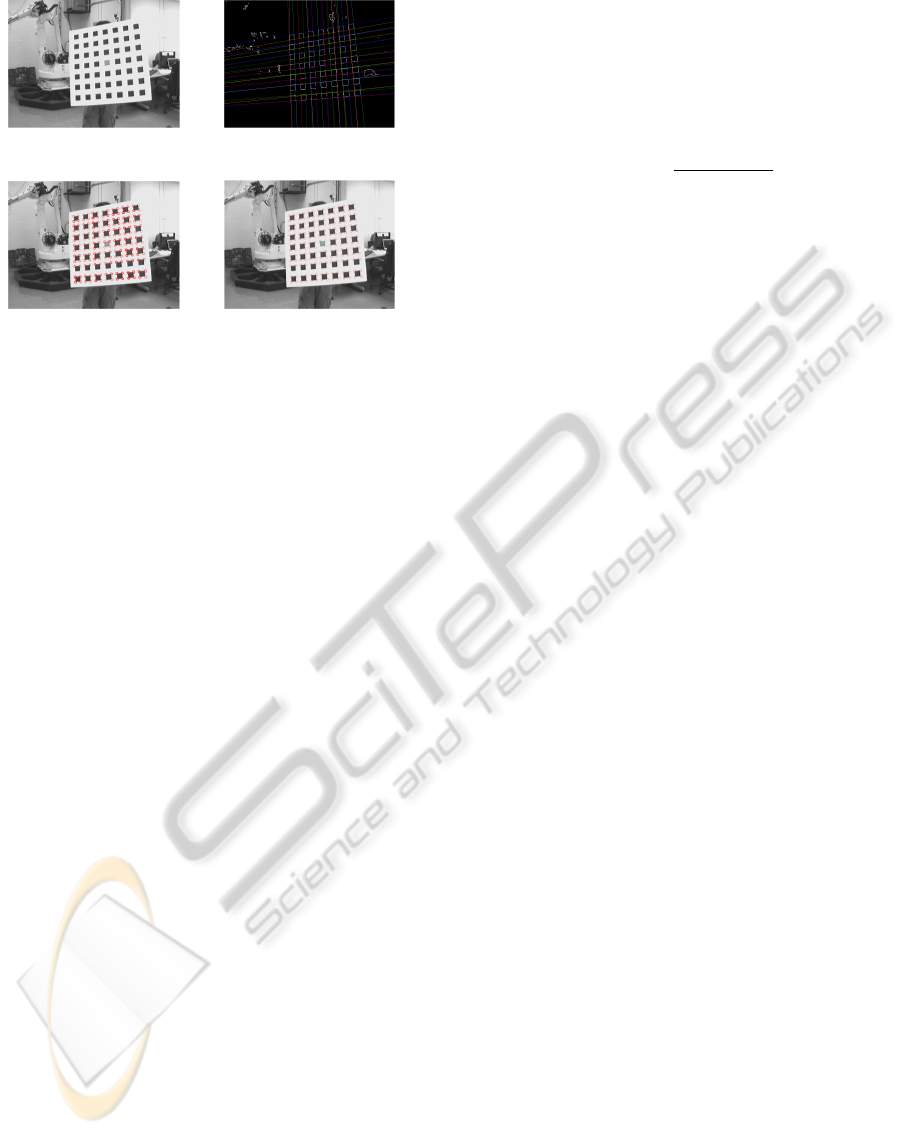
(a) original image (b) detected lines
(c) detected features (d) final detected corners
Figure 1: Steps of the detection algorithm in (Han and DeS-
ouza, 2007).
bration in terms of the final error in 3D reconstruc-
tion for any given subset of the cameras. In order to
achieve that, the system only requires that a sequence
of images be captured by the cameras while a hu-
man presents a calibration pattern at arbitrary poses
in front of the cameras. Then the proposed algorithm
automatically: searches for feature points on the pat-
tern that will be used for calibration; selects the best
set of images that optimizes the overall accuracy from
calibration; and computes the individual camera cal-
ibrations as well as the best sequence of transforma-
tions from the camera to a global coordinate frame.
2 THE PROPOSED ALGORITHM
As we mentioned earlier, the proposed framework for
the calibration of multiple cameras in a vision sensor
network consists of several steps. In this paper we
will focus only on steps 2, 3 and 5 above.
Figures 1(a)-(d) show the various steps of our fea-
ture detection algorithm developed in (Han and DeS-
ouza, 2007). As illustrated by these figures, a small
number of spurious lines and consequently spurious
feature points are initially detected due to noise in the
image. However, after a few more steps into the de-
tection algorithm, all spurious feature points are elim-
inated, as depicted in Figure 1(d). Finally, given the
shape of the pattern, the algorithm automatically es-
tablishes an order to each corner point. This ordering
system is later used for feature correspondence.
The existence of noise in the images greatly af-
fects the performance of the feature detection algo-
rithm. Hence, it is necessary to evaluate these images,
assign a score to them, and choose only those that can
lead to the best calibration. The algorithm initially as-
signs a uniform score of 100 to every image acquired.
Then, algorithm starts to deduct a penalty whenever
the image fails to satisfy a certain expectation. To
rank the image, the penalty is formulated as:
Score
j
= 100 − 100 ×
∑
n
i=1
p
i
+ s
i
× | N − n |
s
i
= max (stdv
u
i
) + max(stdv
v
i
)
p
i
=
(
stdv
u
i
+stdv
v
i
)
N
(1)
Where stdv
u
i
and stdv
v
i
are the standard deviations
in, respectively, the u and v coordinates of detected
corners; N is the total number of corners in the pattern
and n is the number of corners detected. The rationale
behind this scoring scheme is to assign a penalty that
is proportional to the uncertainty (stdv) in the detected
feature point.
Once an image rank is created using the above
scores, the algorithm must start selecting images for
calibration. We cluster the images according to two
non-exclusive criteria: orientation (straight-centered,
tilted-forward, tilted-backward, tilted-to-the-left and
tilted-to-the-right) of the pattern and its distance
(near, medium and far) to the camera. The cluster-
ing of the images is performed by a K-means algo-
rithm using the the angles of the edges and the pat-
tern’s apparent size. Once the clusters are formed,
the algorithm selects for each camera calibration five
images according to the rank Score
j
. That is, one im-
age from each of the five orientations is selected from
the medium clusters. Next, two more images from the
near and far clusters are selected based solely on their
ranks – that is, these images can come from any of the
five orientation clusters. Finally, two extra images of
the pattern are selected for every pair of cameras that
share a view of the pattern at that pose. Once the im-
ages are chosen, the calibration is performed using a
popular method found in the literature (Zhang, 2000).
The final step of the algorithm is the problem of
finding the best transformation from the coordinate
frame of any camera i to any camera j. However, not
all possible paths between cameras assure the same
accuracy in 3D reconstruction. Due to the quality
of the image used for calibration, some paths may
lead to better accuracy than others. We approached
this problem using a graph search algorithm which
is the same as the problem of finding all-pairs short-
est paths. We first compute the shortest-path where
weights are scored as described above. Next we ap-
ply the Floyd-Warshall Algorithm (Floyd, 1962) to
find the best path and therefore the best transforma-
tion between camera coordinate systems.
EXPERIMENTING WITH AUTONOMOUS CALIBRATION OF A CAMERA RIG ON A VISION SENSOR
NETWORK
235
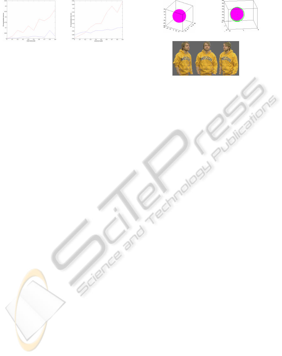
(a) no radial distortion (b) with radial distortion
Figure 2: Errors of 3d reconstruction vs. levels of noise.
Blue lines denote the errors using the best images and red
lines denote the errors using poorly ranked images.
3 EXPERIMENTAL RESULTS
We tested our proposed algorithm for two different
situations. The first group of tests was done with syn-
thetic data and we used from 6 to 42 virtual cameras.
The second group of tests was done with real data us-
ing 6 cameras.
Using the intrinsic parameters from real cameras,
we initially created a virtual space with 18 cameras –
all pointing to the center of the space. We set the ori-
gin of this space at the center, so that the positions of
all 18 cameras could be easily determined. These ar-
bitrary intrinsic and extrinsic parameters of the cam-
eras will later be referred to as our ground truth. Next,
two thousand positions of the synthetic pattern were
randomly generated and noise plus camera radial dis-
tortion were added at various levels to simulate the
effects of real data. One last position of the pattern
was created separately from the training set for test-
ing purpose. The above procedure was repeated 10
times and the results were averaged over all trials.
The amount of noise and distortion added var-
ied through the entire experiment. However, even
when the amount of noise – the standard deviation
of a white (Gaussian) noise – is 2 pixels, the algo-
rithm still performs very well, with less than 1cm of
error in 3D reconstruction. Also, in order to con-
trast the algorithm with a bad scenario in which the
images for calibration are not appropriately selected,
we compared the performance of the calibration us-
ing images that scored poorly. Figures 2(a) and (b)
show the error in 3D reconstruction as a function of
the noise. The error is calculated as the difference
between the estimated (reconstructed) coordinates of
the test points and the ground truth. Figure 2(a) shows
the simulation performed without adding radial dis-
tortion, while for 2(b), a typical radial distortion (from
the real lenses) of 0.3 was added.
We also tested our algorithm with real data. Us-
ing the calibration parameters obtained using the pro-
posed algorithm and the pixel coordinates of a set of
predefined points in space as perceived by all 6 cam-
(a) synthetic sphere (b) real sphere
(c) human upper body in (Lam et al., 2009)
Figure 3: 3D Reconstructions.
eras, we reconstructed the spatial coordinates of these
points and compared the calculated values with the
real ones.
The calibration error was measured by averaging
the results for 20 different snapshots while present-
ing the reference points to all cameras. The reference
points were exactly 50cm apart. Each snapshot was
taken by all 6 cameras, so a total of 120 images were
used for this test. The accuracy of the final calibra-
tion was determined by calculating the distance be-
tween two reference points. The accuracy in 3D re-
construction was 50.6264cm – or less than 1.5% of the
actual distance. Also, the small standard deviation
(0.2498cm) shows that the calibration obtained with
our algorithm gives a very consistent 3D reconstruc-
tion. It is important to mention that, for the current
baseline of the cameras, a deviation of a single pixel
in the location of the marks on the ruler already incurs
on an error of almost 3mm in the reconstruction.
4 3D OBJECT MODELING
Since the main application for our camera rig is for
3D object modeling, we tested the accuracy of the cal-
ibration by reconstructing a sphere based on the idea
of visual hull (Laurentini, 1994) and the human body
using an algorithm for multi-view 3D modeling pre-
sented in (Lam et al., 2009). As before, the tests were
conducted for both synthetic data and real data.
In the first case, synthetic data, we created multi-
ples of 6 virtual cameras (6, 12, 18, . . .) arbitrarily po-
sitioned around the object. By utilizing intrinsic and
distortion parameters, we synthesized the images of
a sphere (ball) with 20cm of radius. Using the voxel
carving approach (Dyer, 2001), we reconstructed the
sphere and measured its radius. In simple terms, this
approach consists of: 1) defining a set of voxels in
the 3D space; 2) marking each voxel according to the
occupancy of the object as projected onto each of the
ICINCO 2010 - 7th International Conference on Informatics in Control, Automation and Robotics
236

Table 1: Estimated radii vs. the number of virtual cameras.
# of virtual cameras 6 12 18 24 30 36 42
estimated radius (cm) 21.53 21.35 21.00 20.43 20.25 20.15 20.15
6n image planes; and 3) finding the intersection of the
occupancy for all 6n cameras. Table 1 shows the re-
lationship between the reconstructed radii versus the
number of cameras used for reconstruction. As ex-
pected, the error decreases as the number of cameras
increases. That is because, among other reasons, the
occupancy defined by each camera view forms a cone
in space and the intersection of any subset of camera
views approximates the sphere by the surface of such
cones. Every time a new camera is added to the sub-
set, the approximation becomes closer to the actual
shape of the sphere. Since this procedure also relies
on a sphere-fitting algorithm to circumscribe the oc-
cupied voxels, the detected radius tends always to be
larger than the actual radius. For the real data, six
cameras were used to take images of a ball. For each
image, a circular Hough transform was used to detect
the boundary and the 2D radius of the ball. As before,
we relied on a voxel carving approach to reconstruct
the ball. Figures 3(a) and (b) depict the reconstructed
sphere for both synthetic data and real data. For the
real ball, also with 20cm of radius, a 3D sphere was
fitted and the radius was estimated. The performance
of the framework using real cameras was 24.3cm. Fi-
nally, Figure 3(c) depicts the result from our multi-
view algorithm for 3D modeling.
5 CONCLUSIONS
We have presented a novel method for autonomous
camera calibration of a multi-camera rig. The exper-
imental results showed that the algorithm is vital in
order to obtain good 3D reconstruction. That is, the
algorithm’s selection of the best images for calibra-
tion leads to an improved calibration of as much as ten
times of that obtained without using the algorithm. Fi-
nally, an application for the camera rig was presented
where a sphere was placed in the middle of the rig
and a 3D representation of the same sphere was con-
structed with an error in reconstruction (real camera)
approaching the theoretical (synthetic cameras) error.
REFERENCES
Baker, A. and Aloimonos, Y. (2000). Complete calibra-
tion of a multi-camera network. In Proceedings of
IEEE International Workshop on Omnidirectional Vi-
sion. IEEE Computer Society.
Chen, K., Hung, Y., and Chen, Y. (2005). Calibrating a cam-
era network using parabolic trajectories of a bouncing
ball. In Proceedings of IEEE International Workshop
on VS-PETS. IEEE Computer Society.
Dyer, C. (2001). Volumetric scene reconstruction from mul-
tiple views. In Foundations of Image Understanding.
Kluwer.
Floyd, R. (1962). Algorithm 97: Shortest path. Commun.
ACM, 5(6):345.
Han, K. and DeSouza, G. N. (2007). A feature detection
algorithm for autonomous camera calibration. In Pro-
ceedings of Fourth International Conference on Infor-
matics in Control, Automation and Robotics.
Huang, Z. and Boufama, B. (2002). A semi-automatic cam-
era calibration method for augmented reality. In Pro-
ceedings of IEEE International Conference on System,
Man and Cybernetics. IEEE Computer Society.
Jaynes, C. (1999). Multi-view calibration from planar mo-
tion for video surveillance. In Proceedings of IEEE
International Workshop on Visual Surveillance. IEEE
Computer Society.
Koller, D., Klinker, G., Rose, E., Breen, D., Whitaker, R.,
and Tuceryan, M. (1997). Automated camera cali-
bration and 3d egomotion estimation for augmented
reality applications. In Proceedings of the 7th Inter-
national Conference on Computer Analysis of Images
and Patterns. Springer-Verlag.
Lam, D., Hong, R., and DeSouza, G. (2009). 3d hu-
man modeling using virtual multi-view stereopsis
from on-the-fly motion estimation. In Proceedings
of IEEE/RSJ International Conference on Intelligent
Robots and Systems. IEEE Computer Society.
Laurentini, A. (1994). The visual hull concept for
silhouette-based image understanding. IEEE Trans-
actions on Pattern Analysis and Machine Intelligence.
Olsen, B. and Hoover, A. (2001). Calibrating a camera net-
work using a domino grid. Pattern Recognition, 34.
Remagnino, P. and Jones, G. (2002). Registration of surveil-
lance data for multi-camera. In IEEE International
Conference on Information Fusion. IEEE Computer
Society.
Svoboda, T., Martinec, D., and Pajdla, T. (2005). A conve-
nient multicamera self-calibration for virtual environ-
ments. MIT Press, Cambridge.
Yamazoe, H., Utsumi, A., and Abe, S. (2006). Multiple
camera calibration with bundled optimization using
silhouette geometry constraints. In Proceedings of
the 18th International Conference on Pattern Recog-
nition. IEEE Computer Society.
Zhang, Z. (2000). A flexible new technique for camera cal-
ibration. IEEE Transactions on Pattern Analysis and
Machine Intelligence.
EXPERIMENTING WITH AUTONOMOUS CALIBRATION OF A CAMERA RIG ON A VISION SENSOR
NETWORK
237
