ANALYSIS OF SNOW 3G
⊕
RESYNCHRONIZATION MECHANISM
Alex Biryukov, Deike Priemuth-Schmid and Bin Zhang
LACS, University of Luxembourg, Rue Richard Coudenhove-Kalergi 6, Luxembourg, Luxembourg
Keywords:
Stream ciphers, SNOW 3G, Resynchronization attack.
Abstract:
The stream cipher SNOW 3G designed in 2006 by ETSI/SAGE is a base algorithm for the second set of 3GPP
confidentiality and integrity algorithms. This paper is the first attempt of cryptanalysis of this algorithm in the
public literature. We look at SNOW 3G in which two modular additions are replaced by xors, which is called
SNOW 3G
⊕
. We show that the feedback from the FSM to the LFSR is very important, since we can break
a version without such a feedback using a pair of known IVs with practical complexities (2
57
time and 2
33
keystream). We then extend this technique into a differential chosen IV attack on SNOW 3G
⊕
and show how
to break 16 out of 33 rounds with the feedback.
1 INTRODUCTION
The SNOW 3G stream cipher is the core of the 3GPP
confidentiality and integrity algorithms UEA2 and
UIA2, published in 2006 by the 3GPP Task Force
(ETSI1, 2006). Compared to its predecessor, SNOW
2.0 (Ekdahl and Johansson, 2002), SNOW 3G adopts
a finite state machine (FSM) of three 32-bit words
and 2 S-Boxes to increase the resistance against alge-
braic attacks by Billet and Gilbert (Billet and Gilbert,
2005). Full evaluation of the design is not public, but
a survey of this evaluation is given in (ETSI2, 2006).
In (ETSI2, 2006), SNOW 3G
⊕
(in which the two
modular additions are replaced by xors) is defined and
evaluated. It shows that SNOW 3G has remarkable
resistance against linear distinguishing attacks (Ny-
berg and Wall´en, 2006; Watanabe et al., 2004), while
SNOW 3G
⊕
offers much better resistance against al-
gebraic attacks.
In this paper, we presents the first attempt of
cryptanalysis of the resynchronization mechanism of
SNOW 3G
⊕
. We show that the feedback from the
FSM to the LFSR during the key/IV setup phase is vi-
tal for the security of this cipher, since we can break a
version without such a feedback with two known IV’s
in 2
57
time, 2
33
data complexity and for an arbitary
number of the key/IV setup rounds! We then restore
the feedback and study SNOW 3G
⊕
against differen-
tial chosen IV attacks. We show attacks on SNOW
3G
⊕
with 14, 15 and 16 rounds of initialization with
complexity 2
42.7
, 2
92.2
and 2
124.2
respectively.
This paper is organized as follows. We give a de-
scription of SNOW 3G and SNOW 3G
⊕
in Section
2. The known IV attack on SNOW 3G
⊕
without the
FSM to LFSR feedback is presented in Section 3 and
the differential chosen IV attack on SNOW 3G
⊕
with
the feedback is presented in Section 4. Finally, some
conclusions are given in Section 5.
2 DESCRIPTION OF SNOW 3G
AND SNOW 3G
⊕
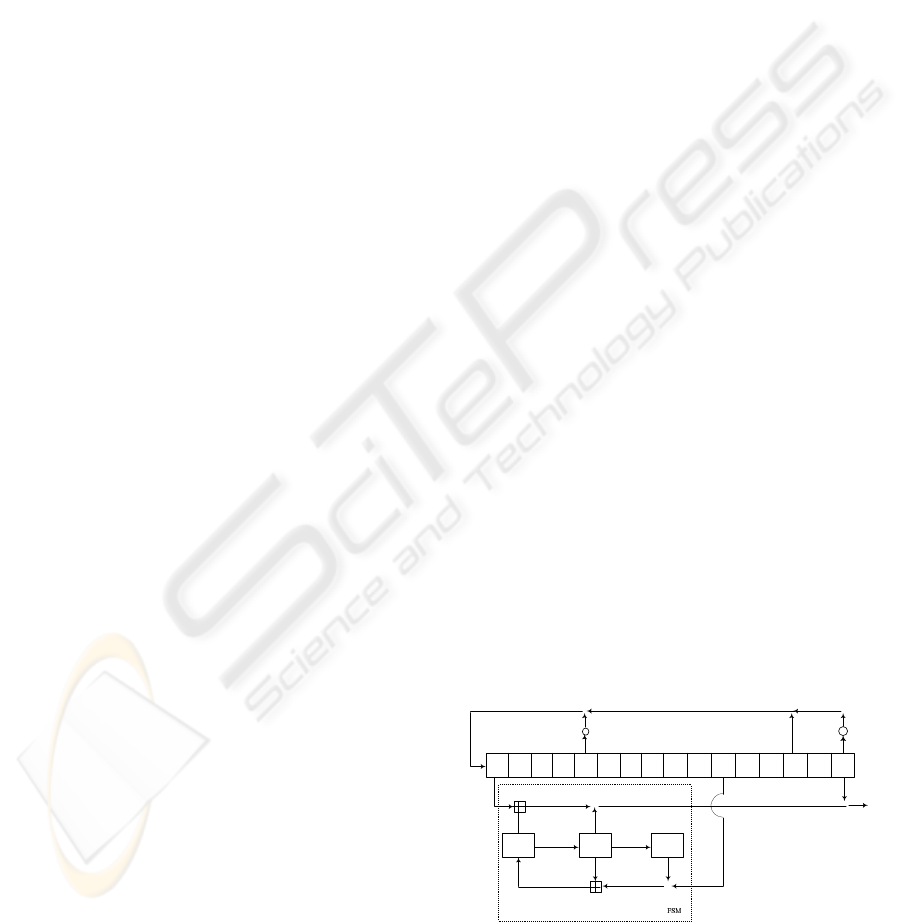
SNOW 3G is a word-oriented synchronous stream ci-
pher with 128-bit key and 128-bit IV, each consid-
ered as four 32-bit words vector. It consists of a lin-
ear feedback shift register (LFSR) of sixteen 32-bit
words and a finite state machine (FSM) with three
32-bit words, shown in Figure 1. Here ’⊕’ denotes
15
s
14
s
13
s
12
s
11
s
10
s
9
s
8
s
7
s
6
s
5
s
4
s
3
s
2
s
1
s
0
s
⊕
⊕
⊕
⊕
⊕
1
R
2
R
3
R
1
S
2
S
•
α
1−
α
•
⊕
t
z
Figure 1: Keystream generation of SNOW 3G.
the bit-wise xor and ’⊞’ denotes the addition modulo
2
32
. The feedback word of the LFSR is recursively
327
Biryukov A., Priemuth-Schmid D. and Zhang B. (2010).
ANALYSIS OF SNOW 3G⣸T RESYNCHRONIZATION MECHANISM.
In Proceedings of the International Conference on Security and Cryptography, pages 327-333
DOI: 10.5220/0002926603270333
Copyright
c
SciTePress

computed as
s
t
15
= α
−1
· s
t−1
11
⊕ s
t−1
2
⊕ α · s
t−1
0
,
where α is the root of the GF(2
8
)[x] polynomial x
4
+
β
23
x
3
+ β
245
x
2
+ β
48
x+ β
239
with β being the root of
the GF(2)[x] polynomial x
8
+ x
7
+ x
5
+ x
3
+ 1. The
FSM has two input words s
t
5
and s
t
15
from the LFSR
and is updated as
R
t
1
= R
t−1
2
⊞ (R
t−1
3
⊕ s
t−1
5
),
R
t
2
= S
1
(R
t−1
1
), R
t
3
= S
2
(R
t−1
2
),
with the output word F
t
= (s
t
15
⊞ R
t
1
) ⊕ R
t
2
, where S
1
and S
2
are 32-bit to 32-bit S-boxes defined as com-
positions of 4 parallel applications of two 8-bit to 8-
bit small S-boxes, S
R
and S
Q
, with a linear diffusion
layer respectively. Here S
R
is the well known AES S-
box and S
Q
is defined as S
Q
(x) = x⊕ x
9
⊕ x
13
⊕ x
15
⊕
x
33
⊕ x
41
⊕ x
45
⊕ x
47
⊕ x
49
⊕ 0x25 for x ∈ GF(2
8
) de-
fined by x
8
+ x
6
+ x
5
+ x
3
+ 1. If we decompose a
32-bit word B into four bytes B = B
0
kB
1
kB
2
kB
3
with
B
0
being the most and B
3
the least significant bytes,
then for i = 1,2, the S-boxes are
S
i
(B) = MC
i
· (S
R
(B
0
),S
R
(B
1
),S
R
(B
2
),S
R
(B
3
))
T
,
where MC
1
is the AES mix-column for S
1
over
GF(2
8
) defined by x
8
+ x
4
+ x
3
+ x + 1 and MC
2
is
the similar operation for S
2
over GF(2
8
) defined by
x
8
+ x
6
+ x
5
+ x
3
+ 1.
SNOW 3G is initialized with the key K =
(k
0
,k
1
,k
2
,k
3
) and the IV = (IV
0
,IV
1
, IV
2
,IV
3
) as fol-
lows. Let 1 be the all-one word, the LFSR is initial-
ized as follows.
s
15
= k
3
⊕ IV
0
s
14
= k
2
s
13
= k
1
s
12
= k
0
⊕ IV
1
s
11
= k
3
⊕ 1 s
10
= k
2
⊕ 1⊕ IV
2
s
9
= k
1
⊕ 1⊕ IV
3
s
8
= k
0
⊕ 1 s
7
= k
3
s
6
= k
2
s
5
= k
1
s
4
= k
0
s
3
= k
3
⊕ 1 s
2
= k
2
⊕ 1 s
1
= k
1
⊕ 1
s
0
= k
0
⊕ 1 .
The FSM is initialized with R
1
= R
2
= R
3
= 0. Then
run the cipher 32 times with the FSM output F xored
to the feedback of the LFSR and no keystream gen-
erated. After this, the cipher is switched into the
keystream generation mode, but the first keystream
word is discarded. Hence, there are 33 initialization
rounds. The keystream word generated at clock t is
z
t
= s
t
0
⊕ F
t
. If we replace the two modulo additions
in SNOW 3G by xors, we get SNOW 3G
⊕
.
3 KNOWN IV ATTACK ON SNOW
3G
⊕
WITHOUT FSM TO LFSR
FEEDBACK
In this section, we consider a known IV attack on
SNOW 3G
⊕
without the FSM to LFSR feedback, in
which the attacker has access to two keystreams cor-
responding to (K,IV
a
) and (K,IV
b
), where IV
a
and
IV
b
are arbitrary known IVs. This attack works for
any number of key/IV setup rounds.
Let R
t
i,a
and R
t
i,b
be the individual values in the
FSM register R
i
at clock t, then we have
∆R
t
1
= R
t
1,a
⊕ R
t
1,b
,
R
t
2,a
= S
1
(R
t−1
1,a
), R
t
2,b
= S
1
(R
t−1
1,b
),
∆R
t
2
= R
t
2,a
⊕ R
t
2,b
= S
1
(R
t−1
1,a
) ⊕ S
1
(R
t−1
1,b
).
Here we define a new notation
out
∆
S
1
(∆R
t−1
1
) , S
1
(R
t−1
1,a
) ⊕ S
1
(R
t−1
1,b
).
During the keystream generation, we have the follow-
ing equations for the differences at clock t
∆z
t
= ∆s
t
15
⊕ ∆R
t
1
⊕ ∆R
t
2
⊕ ∆s
t
0
,
∆R
t
1
= ∆R
t−1
2
⊕ ∆R
t−1
3
⊕ ∆s
t−1
5
,
∆R
t
2
=
out
∆
S
1
(∆R
t−1
1
), ∆R
t
3
=
out
∆
S
2
(∆R
t−1
2
).
The differences in the LFSR part propagate linearly
and are completely predictable.
The main procedures of our attack are: assume
that at time t we have ∆R
t
1
= 0. From the linear evo-
lution of the difference in the LFSR and the keystream
difference equations, we deduce potential differences
in the other FSM registers at different times. Know-
ing the input-output difference for the S-boxes, de-
duce the few possibilities for the actual values of the
FSM registers. Combine the knowledge of the FSM
state with that of the keystream to get linear equations
on the LFSR state. Collect enough equations to get
a solvable linear system which will recover the state
of the LFSR. By the invertibility of the cipher, run it
backwards to find the 128-bit secret key K.
Assume ∆R
t
1
= 0. If this is not true, we just take
the next clock and so on. If we try this step 2
32
times,
then it will happen with a good probability. Denote
the time that ∆R
1
= 0 by t = 1. Then ∆R
1
1
= 0, ∆R
2
2
=
0 and ∆R
3
3
= 0. From the keystream equation at t = 1,
we know ∆R
1
2
; similarly we know ∆R
2
1
at t = 2, from
which we can derive ∆R
1
3
, as shown below. Hereafter,
we denote the known difference values by ∆k
i
.
clock t ∆R
1
∆R
2
∆R
3
1 0 ∆k
1
∆k
3
2 ∆k
2
0
3 0
At t = 3, we have
∆R
2
3
⊕ ∆R
3
2
= ∆z
3
⊕ ∆s
3
15
⊕ ∆s
2
5
⊕ ∆s
3
0
.
By the notations introduced before, we get
out
∆
S
2
(∆k
1
)⊕
out
∆
S
1
(∆k
2
) = ∆k
4
. (1)
SECRYPT 2010 - International Conference on Security and Cryptography
328
Here we have 2
28
· 2
28
/2
32
= 2
24
pairs satisfying (1).
(In the two 8-bit S-boxes, there are at most 2
7
possible
output differences for any fixed input difference.) To
enumerate the possible pairs, we proceed as follows.
First rewrite (1) as
out
∆
S
R
(∆k
0
2
)
out
∆
S
R
(∆k
1
2
)
out
∆
S
R
(∆k
2
2
)
out
∆
S
R
(∆k
3
2
)
=
out
∆
S
Q
(∆k
0
1
)
out
∆
S
Q
(∆k
1
1
)
out
∆
S
Q
(∆k
2
1
)
out
∆
S
Q
(∆k
3
1
)
⊕
p
msb
0
p
msb
1
p
msb
2
p
msb
3
⊕ MC
−1
1
·
∆k
0
4
∆k
1
4
∆k
2
4
∆k
3
4
,
where p
msb
i
(i = 0,1,2, 3) denotes a byte polynomial
which contains only the most significant bits of all the
four
out
∆
S
Q
values. For a detailed explanation, please
see the Appendix. Thus we can fulfill the enumer-
ation byte by byte. For the first row, we need the
value of
out
∆
S
Q
(∆k
0
1
), which has 2
7
possibilities and
three more bits for p
msb
0
. Then we check whether the
value computed at the right side of the equation is a
correct valuefor
out
∆
S
R
(∆k
0
2
). This would cost 2
10
steps
and we will obtain 2
9
solutions for this equation. For
the next three equations, since we already know the
leading bits, we only have 2
6
possibilities left in each
byte equation, which yields the same time complex-
ity and 2
5
solutions. To get the solution of the word
equation, we have to combine the corresponding byte
solutions and get 2
9
·2
5
·2
5
·2
5
= 2
24
solutions, which
needs about 2× 2
24
= 2
25
words of memory. Now,
the states of the FSM are as follows.
clock t ∆R
1
∆R
2
∆R
3
1 0 ∆k
1
∆k
3
2 ∆k
2
0 (2
24
)
3 (2
24
) (2
24
) 0
4
next
part
→
reduction
clock t ∆R
1
∆R
2
∆R
3
1 0 ∆k
1
∆k
3
2 ∆k
2
0 (2
20
)
3 (2
20
) (2
20
) 0
4 (2
20
) (2
20
)
Each possible value of ∆R
3
2
results in a possible value
of ∆R
4
1
. At t = 4, we have
∆R
3
2
⊕ ∆R
4
2
= ∆z
4
⊕ ∆s
4
15
⊕ ∆s
3
5
⊕ ∆s
4
0
.
Replacing the difference ∆R
4
2
with the S-Box repre-
sentation, we receive ∆R
3
2
⊕
out
∆
S
1
(∆R
3
1
) = ∆k
5
. Let
∆R
3
1
= c
0
kc
1
kc
2
kc
3
, ∆R
3
2
= a
0
ka
1
ka
2
ka
3
. Expanding
this equation to the byte form, we get
out
∆
S
R
(c
0
)
out
∆
S
R
(c
1
)
out
∆
S
R
(c
2
)
out
∆
S
R
(c
3
)
= MC
−1
1
·
a
0
a
1
a
2
a
3
⊕ MC
−1
1
·
∆k
0
5
∆k
1
5
∆k
2
5
∆k
3
5
.
We have to insert all the 2
24
possible pairs of
(∆R
3
2
,∆R
3
1
) and verify the value
out
∆
S
R
for the sin-
gle bytes. This results in a time complexity of
2
24
. There are
2
24
·2
28
2
32
= 2
20
entries satisfy this
equation. This means we have 2
20
sequences
(∆R
2
3
,∆R
3
1
,∆R
3
2
,∆R
4
1
,∆R
4
2
) left. For each of them, we
know the input-output difference of S
1
at clock 2 and
3. Thus, we can recover (2·
126
127
+ 4 ·
1
127
)
4
= 16.51
sorted pairs of values for S
1
. This means that we have
16.51
2
= 8.255 possible values for ∆R
4
3
. Looking at
clock 5, we have ∆R
4
2
⊕ ∆R
4
3
⊕
out
∆
S
1
(∆R
4
1
) = ∆k
6
. We
can rewrite this equation into byte form and check
the 2
20
remaining sequences by the byte equations.
There are
2
20
·8.255·2
28
2
32
≈ 2
19.05
possible sequences left
and the complexity is about 2
20
· 8.255 = 2
23.05
. This
identification of the individual values in the FSM for
both keystreams has to be repeated for the next 9
clocks. Each step will have a lower time complex-
ity than the one before and will reduce the possible
number of differences. The time complexity for all
10 steps together is
∑
9
i=0
2
20
·(
2
27
127
4
)
i
·
2
31
127
4
= 2
24.1
and
the number of sequences left is 2
20
· (
2
27
127
4
)
10
= 2
10.5
.
Then we insert the individual values of the FSM into
the keystream generation equations and the FSM up-
date equations to get a linear system of the LFSR
initial states. This would need a time complexity of
2
10.5
· 2
10
= 2
20.5
steps. The overall time complexity
is
2
32
· [2
10
+ 2
24
+
9
∑
i=0
(2
20
· (
2
27
127
4
)
i
·
2
31
127
4
)] = 2
57.1
.
The memory requirement is 2
25
words and the
keystream is of length 2
33
words.
4 DIFFERENTIAL CHOSEN IV
ATTACKS ON REDUCED
ROUND SNOW 3G
⊕
Now we look at the full SNOW 3G
⊕
(with the feed-
back). We consider a differential chosen IV attack
scenario. Assume that we have two 128-bit IVs dif-
fering only in the most significant word IV
0
, which
gives the difference in s
15
of the LFSR. As mentioned
þÿANALYSIS OF SNOW 3G"• RESYNCHRONIZATION MECHANISM
329

below in Section 4.2 and Section 4.3, we can restrict
the difference to a single byte of IV
0
in order to reduce
the complexity of our attacks. Denote this difference
by ∆d. Then until round 10, this difference will not
affect the FSM. In round 11, the known ∆d enters the
FSM word R
1
.
4.1 Reduced Initialization of 12 Rounds
Since all the differences in the FSM are 0, there are
no differences fed back into the LFSR. Thus the dif-
ferences in the LFSR are all known. Our knowledge
of differences in the FSM is shown below. We try to
compute the unknown values (”?”s) in this table.
round clock t ∆R
1
∆R
2
∆R
3
11 −1 ∆d 0 0
12 0 ∆d ? 0
1 ? ?
From the keystream equation ∆z
0
= ∆s
0
15
⊕ ∆R
0
1
⊕
∆R
0
2
⊕ ∆s
0
0
, where ∆R
0
1
= ∆d, we get ∆R
0
2
, which
gives us immediately ∆R
1
1
and also ∆R
1
2
from the
next keystream equation. Therefore, we have only
one known sequence (∆R
−1
1
= ∆d, ∆R
−1
2
= ∆R
−1
3
=
0, ∆R
0
1
= ∆d, ∆R
0
2
,∆R
0
3
= 0, ∆R
1
1
,∆R
1
2
). Now we
know the input and output difference of S
1
: ∆R
−1
1
=
∆d → S
1
→ ∆R
0
2
. Thus, we switch from the differ-
ences of the FSM words to the individual values of
them, similar to the procedures explained in Section
3. The time complexity is 10 ·
2
31
127
4
= 2
6.4
steps. Af-
terwards we insert the individual values of the FSM
into the keystream generation equations and the FSM
update equations to get a linear system of the LFSR
initial states with a complexity of 2
10
. We use the
keystream equation of clock 12 to check the candi-
dates. The total time complexity is 2
6.4
+ 2
10
= 2
10.1
steps, the memory complexity is small and the known
keystream is only 12 words for each IV.
4.2 Reduced Initialization of 13 Rounds
Here we extend the attack above by one more round.
In the 13 round case, since all the differences in the
FSM until now are either 0 or the known ∆d, no un-
known difference was fed back into the LFSR. Thus,
the differences in the LFSR values are known. We
compute ”?”s in the following table as follows.
round clock t ∆R
1
∆R
2
∆R
3
11 −2 ∆d 0 0
12 −1 ∆d ? 0
13 0 ? ?
From ∆z
0
and ∆R
0
1
, we have
∆z
0
= ∆s
0
15
⊕ ∆R
−1
2
⊕ ∆s
−1
5
⊕ ∆R
0
2
⊕ ∆s
0
0
,
which is
∆R
−1
2
⊕ ∆R
0
2
= ∆z
0
⊕ ∆s
0
15
⊕ ∆s
−1
5
⊕ ∆s
0
0
.
Then we replace the differences at the left side with
their S-Boxes description, denote the known part at
the right side with k
0
and get the equation
out
∆
S
1
(∆d)⊕
out
∆
S
1
(∆d) = ∆k
0
.
Multiplying by MC
−1
1
, we get the byte form equation
out
∆
S
R
(∆d
0
)
out
∆
S
R
(∆d
1
)
out
∆
S
R
(∆d
2
)
out
∆
S
R
(∆d
3
)
⊕
out
∆
S
R
(∆d
0
)
out
∆
S
R
(∆d
1
)
out
∆
S
R
(∆d
2
)
out
∆
S
R
(∆d
3
)
= MC
−1
1
∆k
0
0
∆k
1
0
∆k
2
0
∆k
3
0
.
We can check these four byte equations in
4· 2
7
= 2
9
steps. The number of solutions will be
2
28
·2
28
2
32
= 2
24
pairs of (∆R
−1
2
,∆R
0
2
). We have 2
24
sequences (∆R
−2
1
= ∆d, ∆R
−2
2
= ∆R
−2
3
= 0,∆R
−1
1
=
∆d,∆R
−1
2
,∆R
−1
3
= 0,∆R
0
1
,∆R
0
2
). Again, we switch
from the differences of the FSM words to the in-
dividual values of them by using the input and
output difference of S
1
: ∆R
−2
1
= ∆d → S1 →
∆R
−1
2
. The time complexity of this step is
∑
9
i=0
2
24
· (
2
27
127
4
)
i
·
2
31
127
4
= 2
28.09
. In the end, we have
2
24
· (
2
27
127
4
)
10
= 2
14.45
difference sequences left. The
memory complexity is 2
25
· 10· 3 = 2
29.91
words. We
then insert the individual values of the FSM into the
keystream generation equations and the FSM update
equations to get a linear system of the LFSR ini-
tial states. This would need a time complexity of
2
294
127
40
· 2
10
= 2
24.45
. The overall time complexity is
2
9
+
9
∑
i=0
2
24
· (
2
27
127
4
)
i
·
2
31
127
4
+
2
294
127
40
· 2
10
= 2
28.2
steps. The memory complexity is 2
29.91
words and the
keystream is of length 12 words for each IV.
If we restrict the known arbitrary difference ∆d to
a word with three bytes equal to zero and only one non
zero byte, we can reduce our attack complexity con-
siderably. We then have only one pair (∆R
−1
2
,∆R
0
2
)
of difference left, as in the attack on 12 rounds ex-
plained in Section 4.1. In this way, we will have the
same time complexity 2
10.1
and the memory require-
ment is small. The keystream will be of 12 words for
each IV.
4.3 Reduced Initialization of 14 Rounds
Nearly all the differences in the LFSR are known, the
only unknowndifference is ∆R
−2
2
, which was fed back
SECRYPT 2010 - International Conference on Security and Cryptography
330

into the LFSR, the remaining differences are either 0
or the known ∆d. We guess the individual value R
−3
1,a
for the first pair (K,IV
a
) with complexity of 2
32
. From
the value R
−3
1,a
, we get with ∆R
−3
1
= ∆d the value R1
−3
b
for the second pair (K,IV
b
). Furthermore we obtain
R
−2
2,a
,R
−2
2,b
,R
−1
3,a
,R
−1
3,b
. We denote the known difference
∆R
−2
2
with ∆k
0
, the linear dependent ∆R
−1
1
with ∆k
1
and ∆R
−1
3
with ∆k
2
. This gives the following differ-
ences for the FSM.
round clock t ∆R
1
∆R
2
∆R
3
11 −3 ∆d 0 0
12 −2 ∆d ∆k
0
0
13 −1 ∆k
1
? ∆k
2
14 0 ? ?
From
∆z
0
= ∆s
0
15
⊕ ∆R
0
1
⊕ ∆R
0
2
⊕ ∆s
0
0
,
we insert the update equations for ∆R
0
1
and ∆R
0
2
and
receive
∆z
0
= ∆s
0
15
⊕
out
∆
S
1
(∆d) ⊕ ∆k
2
⊕ ∆s
−1
5
⊕
out
∆
S
1
(∆k
1
) ⊕ ∆s
0
0
,
which gives
out
∆
S
1
(∆d)⊕
out
∆
S
1
(∆k
1
)
= ∆z
0
⊕ ∆s
0
15
⊕ ∆k
2
⊕ ∆s
−1
5
⊕ ∆s
0
0
.
We denote the known right part by ∆k
3
, multiply the
equation with MC
−1
1
and rewrite it in byte notation as
out
∆
S
R
(∆d
0
)
out
∆
S
R
(∆d
1
)
out
∆
S
R
(∆d
2
)
out
∆
S
R
(∆d
3
)
⊕
out
∆
S
R
(∆k
0
1
)
out
∆
S
R
(∆k
1
1
)
out
∆
S
R
(∆k
2
1
)
out
∆
S
R
(∆k
3
1
)
= MC
−1
1
∆k
0
3
∆k
1
3
∆k
2
3
∆k
3
3
.
Then we check this equation line by line for each
byte in 4 · 2
7
= 2
9
steps. The number of solutions
will be
2
28
·2
28
2
32
= 2
24
pairs of (∆R
−1
2
,∆R
0
2
). Again,
we switch from the differences of the FSM words to
the individual values of them by using the input and
output difference of S
1
: ∆R
−2
1
→ S
1
→ ∆R
−1
2
. Since
we start with 2
24
sequences, we have completely the
same procedure as in the attack on 13 rounds of ini-
tialization and thus the same complexities. The over-
all time complexity is the same as that in 12 rounds of
initialization for each guess of R1
−3
1
, which gives
2
32
·
"
2
9
+
9
∑
i=0
2
24
·(
2
27
127
4
)
i
·
2
31
127
4
+
2
294
127
40
·2
10
#
=2
60.2
.
The memory requirement is 2
29.91
words and the
keystream is of length 12 words for each IV.
If we restrict the known difference ∆d to only one
byte in IV
0
, we can reduce our attack complexity to
2
42.7
with similar procedures as above. The corre-
sponding memory complexity is 2
9
words and the
keystream is of 12 words for each IV.
4.4 Reduced Initialization of 15 Rounds
and 16 Rounds
Nearly all the differences in the LFSR are known,
only two unknown differences ∆R
−3
2
and ∆R
−2
2
were
fed back into the LFSR, the remaining differences are
either 0 or the known ∆d. We guess the individual
values of R
−4
1,a
and R
−3
1,a
for the first pair (K,IV
a
) with
complexity of 2
64
. From the value R
−4
1,a
and ∆R
−4
1
=
∆d, we get the values of R
−4
1,b
, R
−3
2,a
,R
−3
2,b
, R
−2
3,a
,R
−2
3,b
. De-
note the known difference ∆R
−3
2
by ∆k
0
, ∆R
−2
1
by ∆k
1
and ∆R
−2
3
by ∆k
2
. From R
−3
1,a
and ∆R
−3
1
= ∆d, we get
the values of R
−3
1,b
,R
−2
2,a
,R
−2
2,b
,R
−1
3,a
,R
−1
3,b
. Again, we de-
note the now known difference ∆R
−2
2
by ∆k
3
, ∆R
−1
1
by ∆k
4
and ∆R
−1
3
by ∆k
5
. This gives the following
differences for the FSM.
round clock t ∆R
1
∆R
2
∆R
3
11 −4 ∆d 0 0
12 −3 ∆d ∆k
0
0
13 −2 ∆k
1
∆k
3
∆k
2
14 −1 ∆k
4
? ∆k
5
15 0 ? ?
We have now the same starting point as that of the
attack on 14 initialization rounds. We proceed in the
way as explained there. Since we guessed one more
word in the beginning of the attack, the time complex-
ity becomes
2
32
· 2
60.2
= 2
92.2
.
The memory complexity remains 2
29.91
words and the
keystream is of length 12 words for each IV.
In the 16 rounds case, we guess one more word
and then proceed as that of the attack on 15 rounds.
The time complexity is
2
32
· 2
92.2
= 2
124.2
and the memory complexity remains 2
29.91
words and
the keystream is of length 12 words for each IV.
The summary of our results is given in Table 1.
5 CONCLUSIONS
In this paper, we have shown known IV and chosen
IV resynchronization attacks on SNOW 3G
⊕
. We can
attack arbitrary many key/IV setup rounds of SNOW
3G
⊕
if there is no feedback from FSM to LFSR. With
such feedback, we show key recovery attacks up to
16 rounds of initialization by using a few keystream
words. Our results indicate that about half of the ini-
tialization rounds of SNOW 3G
⊕
might succumb to
chosen IV resynchronization attacks. The remaining
þÿANALYSIS OF SNOW 3G"• RESYNCHRONIZATION MECHANISM
331

Table 1: The summary of our results on SNOW 3G
⊕
.
attack data time memory
SNOW 3G
⊕
2
33
2
57.1
2
25
without feedback
SNOW 3G
⊕
with feedback
12 rounds 24 2
10.1
small
13 rounds with 1 24 2
10.1
small
byte difference ∆d
14 rounds with 1 24 2
42.7
2
9
byte difference ∆d
15 rounds 24 2
92.2
2
29.91
16 rounds 24 2
124.2
2
29.91
security margin however is quite significant and thus
these attacks pose no threat to the security of SNOW
3G itself.
REFERENCES
Billet, O. and Gilbert, H. (2005). Resistance of SNOW 2.0
Against Algebraic Attacks. In Topics in Cryptology-
CT-RSA’2005. LNCS vol. 3376, pp. 19-28. Springer-
Verlag 2005.
Ekdahl, P. and Johansson T. (2002). A New Version of
the Stream Cipher SNOW. In Selected Areas in
Cryptography-SAC 2002. LNCS vol. 1233, pp. 37-46.
Springer-Verlag 2002.
ETSI/SAGE. (2006). Specification of the 3GPP Confiden-
tiality and Integrity Algorithms UEA2 & UIA2. Doc-
ument 2: SNOW 3G Specification, version 1.1 In
September 2006. http://www.3gpp.org/ftp/..
ETSI/SAGE (2006). Specification of the 3GPP Confiden-
tiality and Integrity Algorithms UEA2 & UIA2. Doc-
ument 5: Design and Evaluation Report, version 1.1
In September 2006. http://www.3gpp.org/ftp/.
Nyberg, K. and Wall´en, J. (2006). Improved Linear Distin-
guishers for SNOW 2.0. In Fast Software Encryption-
FSE 2006. LNCS vol. 4047, pp. 144-162. Springer-
Verlag 2006.
Watanabe, D., Biryukov, A., De Canni`ere, Christophe,
(2004). A Distinguishing Attack of SNOW 2.0
with Linear Masking Method. In Selected Areas in
Cryptography-SAC 2003. LNCS vol. 3006, pp. 222-
233. Springer-Verlag 2004.
APPENDIX
We want to simplify the equation
out
∆
S
2
(∆k
1
)⊕
out
∆
S
1
(∆k
2
) = ∆k
4
.
The main difficulty is that S
1
and S
2
use the same
Mix-Column matrix but over two different fields
GF(2
8
). At first we rewrite this equation in the byte
notation as
MC
2
·
out
∆
S
Q
(∆k
0
1
)
out
∆
S
Q
(∆k
1
1
)
out
∆
S
Q
(∆k
2
1
)
out
∆
S
Q
(∆k
3
1
)
⊕ MC
1
·
out
∆
S
R
(∆k
0
2
)
out
∆
S
R
(∆k
1
2
)
out
∆
S
R
(∆k
2
2
)
out
∆
S
R
(∆k
3
2
)
=
∆k
0
4
∆k
1
4
∆k
2
4
∆k
3
4
.
Then multiplying this equation with the inverse ma-
trix MC
−1
1
, we get
MC
−1
1
·
MC
2
·
out
∆
S
Q
(∆k
0
1
)
out
∆
S
Q
(∆k
1
1
)
out
∆
S
Q
(∆k
2
1
)
out
∆
S
Q
(∆k
3
1
)
⊕
out
∆
S
R
(∆k
0
2
)
out
∆
S
R
(∆k
1
2
)
out
∆
S
R
(∆k
2
2
)
out
∆
S
R
(∆k
3
2
)
= MC
−1
1
·
∆k
0
4
∆k
1
4
∆k
2
4
∆k
3
4
.
If we expand the matrix multiplications and have a
look at the byte vectors, it shows that the first entry of
the first vector contains the byte
out
∆
S
Q
(∆k
0
1
) and a byte
polynomial containing only the most significant bits
of all four
out
∆
S
Q
values. We denote this polynomial
with p
msb
0
. The other three rows have similar struc-
tures, but with differentpolynomials p
msb
i
(i = 1, 2,3).
Therefore we can rewrite the equation to
out
∆
S
R
(∆k
0
2
)
out
∆
S
R
(∆k
1
2
)
out
∆
S
R
(∆k
2
2
)
out
∆
S
R
(∆k
3
2
)
=
out
∆
S
Q
(∆k
0
1
)
out
∆
S
Q
(∆k
1
1
)
out
∆
S
Q
(∆k
2
1
)
out
∆
S
Q
(∆k
3
1
)
⊕
p
msb
0
p
msb
1
p
msb
2
p
msb
3
⊕ MC
−1
1
·
∆k
0
4
∆k
1
4
∆k
2
4
∆k
3
4
.
We denote by m
0
the most significant bit of the
value
out
∆
S
Q
(∆k
0
1
) and with m
1
the most significant bit
of the value
out
∆
S
Q
(∆k
1
1
) as well as m
2
for
out
∆
S
Q
(∆k
2
1
)
and m
3
for
out
∆
S
Q
(∆k
3
1
). Then the polynomials p
msb
i
SECRYPT 2010 - International Conference on Security and Cryptography
332

i = 0,. . . ,3 are
p
msb
0
=(m
1
⊕ m
3
)x
7
+ (m
0
⊕ m
1
)x
6
+ (m
2
⊕ m
3
)x
5
+ (m
1
⊕ m
2
)x
4
+ (m
0
⊕ m
2
)x
2
+ (m
1
⊕ m
2
)x
+ (m
0
⊕ m
1
⊕ m
2
⊕ m
3
)
p
msb
1
=(m
0
⊕ m
2
)x
7
+ (m
1
⊕ m
2
)x
6
+ (m
0
⊕ m
3
)x
5
+ (m
2
⊕ m
3
)x
4
+ (m
1
⊕ m
3
)x
2
+ (m
2
⊕ m
3
)x
+ (m
0
⊕ m
1
⊕ m
2
⊕ m
3
)
p
msb
2
=(m
1
⊕ m
3
)x
7
+ (m
2
⊕ m
3
)x
6
+ (m
0
⊕ m
1
)x
5
+ (m
0
⊕ m
3
)x
4
+ (m
0
⊕ m
2
)x
2
+ (m
0
⊕ m
3
)x
+ (m
0
⊕ m
1
⊕ m
2
⊕ m
3
)
p
msb
3
=(m
0
⊕ m
2
)x
7
+ (m
0
⊕ m
3
)x
6
+ (m
1
⊕ m
2
)x
5
+ (m
0
⊕ m
1
)x
4
+ (m
1
⊕ m
3
)x
2
+ (m
0
⊕ m
1
)x
+ (m
0
⊕ m
1
⊕ m
2
⊕ m
3
)
þÿANALYSIS OF SNOW 3G"• RESYNCHRONIZATION MECHANISM
333
