
GRASPING WITH VISION DESCRIPTORS AND MOTOR
PRIMITIVES
Oliver Kroemer
Max Planck Institute for Biological Cybernetics, Spemannstr. 38, 72076 Tuebingen, Germany
Renaud Detry, Justus Piater
University of Liege, Grande Traverse 10, 4000 Liege, Belgium
Jan Peters
Max Planck Institute for Biological Cybernetics, Spemannstr. 38, 72076 Tuebingen, Germany
Keywords:
Dynamical Motor Primitives, Early Cognitive Vision Descriptors, Grasping.
Abstract:
Grasping is one of the most important abilities needed for future service robots. Given the task of picking up
an object from betweem clutter, traditional robotics approaches would determine a suitable grasping point and
then use a movement planner to reach the goal. The planner would require precise and accurate information
about the environment and long computation times, both of which may not always be available. Therefore,
methods for executing grasps are required, which perform well with information gathered from only standard
stereo vision, and make only a few necessary assumptions about the task environment. We propose techniques
that reactively modify the robot’s learned motor primitives based on information derived from Early Cognitive
Vision descriptors. The proposed techniques employ non-parametric potential fields centered on the Early
Cognitive Vision descriptors to allow for curving hand trajectories around objects, and finger motions that
adapt to the object’s local geometry. The methods were tested on a real robot and found to allow for easier
imitation learning of human movements and give a considerable improvement to the robot’s performance in
grasping tasks.
1 INTRODUCTION
Consider the scenario wherein you want to have a hu-
manoid robot grasp an object in a cluttered space. The
first stage of most grasp planners determines a suit-
able grasp location on the object (Saxena et al., 2008;
Arimoto, 2008; Bicchi and Kumar, 2000). Having se-
lected a final location and orientation for the hand, the
robot must then determine how to execute the grasp
so as not to collide with the object or any of the sur-
rounding objects.
The traditional solution for this scenario involves
supplying the robot with a CAD model of the objects
and a laser scanner or other means (ERFID, previous
position, etc.) for obtaining their precise positions.
These tools give the robot ample knowledge to apply
a planning algorithm that determines a suitable path
to the goal. This process relies on precise sensor in-
formation and can be very time consuming given a
complex scene with numerous possible object colli-
sions to test for at each step. In contrast, humans can
perform successful grasps of objects in the periphery
of their vision, where visual information is limited.
Taking inspiration from human movements, we
propose a reactive method for robots grasping ob-
jects in cluttered environments using potential fields
based on only a small amount of visual information.
Specifically, we present methods for incorporating in-
formation derived from Early Cognitive Vision De-
scriptors (ECVD) (Pugeault, 2008) into the dynam-
ical system motor primitives (DMP) (Schaal et al.,
2003) framework. The Early Cognitive Vision sys-
tem (see Appendix and Figure 2) was chosen since it
makes only a few assumptions about the object being
grasped, while the motor primitives (see Appendix)
were chosen because they generalize well to new sit-
uations and can be learned through imitation (Ijspeert
et al., 2002). The two frameworks are also compatible
47
Kroemer O., Detry R., Piater J. and Peters J. (2010).
GRASPING WITH VISION DESCRIPTORS AND MOTOR PRIMITIVES.
In Proceedings of the 7th International Conference on Informatics in Control, Automation and Robotics, pages 47-54
DOI: 10.5220/0002938100470054
Copyright
c
SciTePress
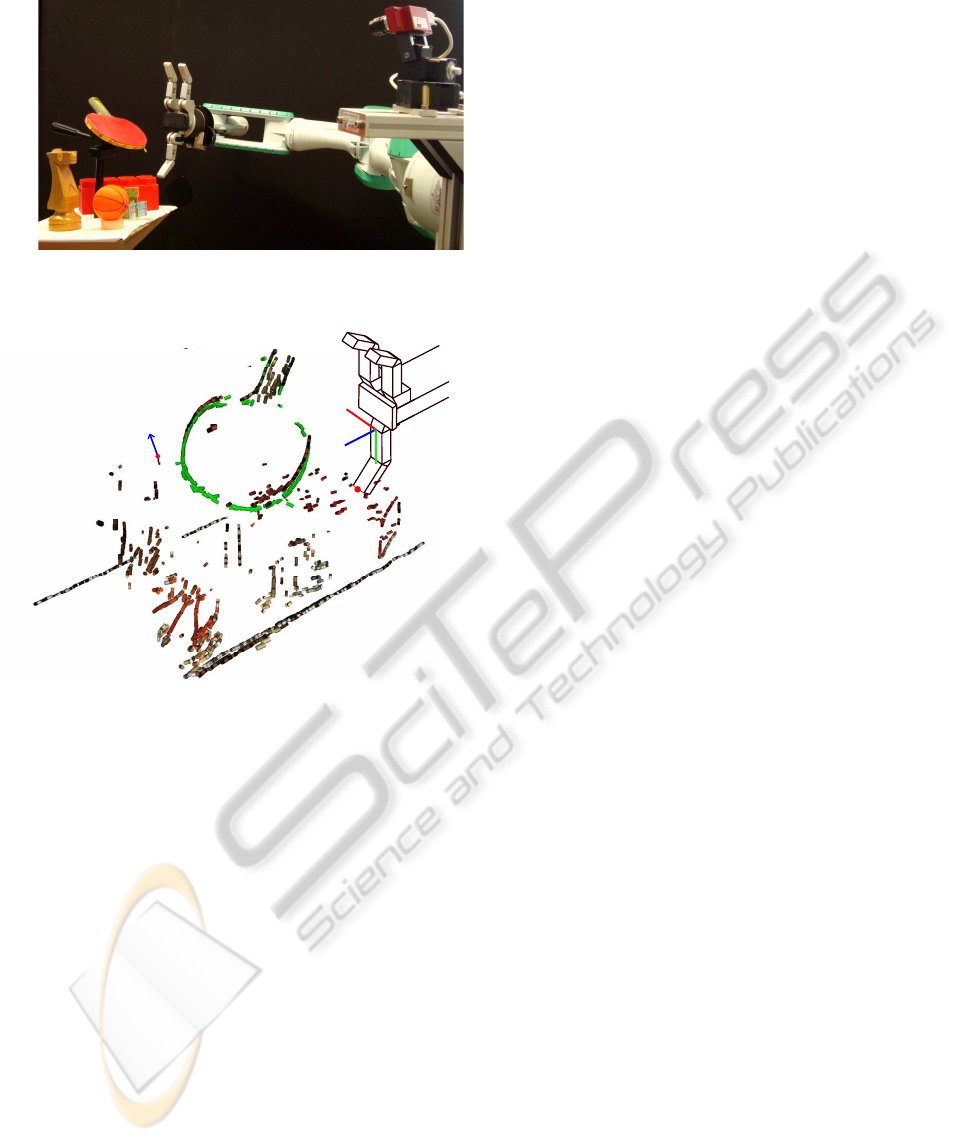
Figure 1: The robot used in our experiments and an example
of a grasping task in a cluttered environment.
e
j
v
j
p
X
Y
Z
Figure 2: The green ECVD represent the object to be
grasped, while the surrounding ECVDs in the scene are
clutter. The coordinate frame of the third finger of the Bar-
rett hand (the lower finger in the image) and variables used
in section 2 are shown. The x-y-z coordinate system is lo-
cated at the base of the finger, with z orthogonal to the palm,
and y in the direction of the finger. The marked ECVD
on the left signifies the j
th
descriptor, with its position at
v
j
= (v
jx
,v
jy
,v
jz
)
T
, and edge direction e
j
= (e
jx
,e
jy
,e
jz
)
T
of unit length. The position of the finger tip is given by
p = (p
x
, p
y
, p
z
)
T
.
with each other and thus straightforward to combine.
The ECVDs were used to elegantly augment the
DMPs for grasping tasks, resulting in the robot being
able to avoid obstacles, curve its reaching trajectories
around the object to grasp, and adapting the fingers to
the local geometry of the object.
2 METHODS FOR REACTIVE
GRASPING
The methods proposed in this section were inspired
by human movements. Human grasping movements
can be modeled as two linked components, trans-
portation and finger posture, synchronized by a shared
timer or canonical system (Chieffi and Gentilucci,
1993; Oztop and Kawato, 2009). Transportation
refers to the actions of the arm in moving the hand,
while the finger posture aspect relates to the preshap-
ing and closing of the fingers (Jeannerod, 1997).
Humans perform the reaching/transportation com-
ponent in a task-specific combination of retina and
hand coordinates (Graziano, 2006), which allows for
easier specification of object trajectories in a manipu-
lation task than joint coordinates would and results in
a reduction in dimensionality. These movements also
have curved trajectories that are needed for avoiding
obstacles and reaching around objects, which mainly
occurs in a planar subspace (Wank et al., 2004).
Similar to the transportation component, the main
purpose of the finger posture component is to pre-
shape the hand by extending the fingers sufficiently
for them to pass around the object upon approach, and
then close on the object simultaneously for a good
grasp. Over-extending the fingers is undesirable as
it makes collisions with the environment more likely
and is therefore usually restricted to situations that
present large uncertainties about the object (Oztop
et al., 2004; Chieffi and Gentilucci, 1993).
Curved reaching trajectories and preshaping of the
hand were incorporated into the robot via a potential
field, as described in Sections 2.1 and 2.2. Subse-
quently, a higher level controller is proposed in Sec-
tion 2.3, which allows the grasping movements to be
interpolated better to new target grasp locations.
2.1 DMP based Attractor Field
The first step towards specifying the grasping move-
ments is to define an attractor field as a DMP that en-
codes the desired movements given no obstacles. The
principal features that need to be defined for these
DMPs are 1) the goal positions, and 2) the generic
shape of the trajectories to reach the goal.
Determining the goal posture of the hand using
the ECV descriptors has been previously investigated
in. (Detry et al., 2009). In this work, possible grasp
locations were hypothesized from the geometry and
color features of the ECVDs, and used to create a ker-
nel density estimate of suitable grasps, which is then
refined by attempting grasps to test them.
However, this grasp synthesizer only gives the
ICINCO 2010 - 7th International Conference on Informatics in Control, Automation and Robotics
48

desired location and orientation of the hand, but
leaves finger placement to a secondary finger con-
troller, e.g., (Hsiao et al., 2009; Steffen et al., 2007).
Using the ECVDs, the goal position of each fin-
ger is approximated by first estimating a contact
plane for the object in the finger coordinate system
shown in Figure 2. To make it a local approxima-
tion, the influence of the i
th
ECVD is weighted by
w
i
= exp(−σ
−2
x
v
2
ix
− σ
−2
y
v
2
iy
− σ
−2
z
v
2
iz
), where σ
x
, σ
y
,
and σ
z
are length scale constants, and v
i
is the po-
sition of the ECVD in the finger reference frame.
The hand orientation was chosen such that the Z di-
rection of the finger is parallel to the approximated
contact plane, which reduces the problem to de-
scribing the plane as a line in the 2D X-Y space.
The X-Y gradient of the plane is approximated by
φ = (
∑
N
i=1
w
i
)
−1
∑
N
i=1
w
i
arctan(e
iy
/e
ix
), where N is
the number of vision descriptors, and e
i
is the direc-
tion of the i
th
edge. The desired Y position of the
fingertip is then given by
˜p
y
=
∑
N
i=1
(w
i
v
iy
− tan(φ)w
i
v
ix
)
∑
N
i=1
w
i
,
which can be easily converted to a joint parameter us-
ing the inverse kinematics of the hand.
Having determined the goals of both transporta-
tion and finger-posture components, the next step is
to define the trajectories used to reach these goals.
Many of the beneficial traits of human movements,
as described earlier, can be transferred to the robot
through imitation learning. Learning by imitation in-
volves a human demonstrating a motion and the robot
then mimicking the movement. Details for imitation
learning with DMPs can be found in (Ijspeert et al.,
2002).
We can now combine the goals and imitation
learned trajectories to specify the DMPs and thus the
attractor fields.
2.2 ECVD based Detractor Fields
Having specified the rudimentary grasping move-
ments, a detractor field is employed to refine the mo-
tions in order to include obstacle avoidance for the
transportation and ensure that the finger tips do not
collide with the object during the hand’s approach.
The detractor field will be based on ECVDs,
which can be envisioned as small line segments of
an object’s edges localized in 3D, as shown in Fig-
ure 2 for a scene as shown in Figure 1. The detractive
potential fields for ECVDs are characterized by two
main features; i.e., the detractive forces of multiple
ECVDs describing a single line do not superimpose,
and the field does not stop DMPs from reaching their
ultimate goals. The system therefore uses a Nadaraya-
Watson model (Bishop, 2006) of the form
u = −s(x)
∑
N
i=1
r
i
c
i
∑
N
j=1
r
j
,
to generate a suitable detractor field, where r
i
is a
weight assigned to the i
th
ECVD, s is the strength of
the overall field, x is the state of the DMPs’ canoni-
cal system, and c
i
is the detracting force for a single
descriptor.
The weight of an ECVD for collision avoidance is
given by r
i
= exp(−(v
i
− p)
T
h(v
i
− p)), where v
i
is
the position of the i
th
ECVD in the local coordinate
system, h is a vector of positive length scale hyper-
parameters, and p is the finger tip position, as shown
in Figure 2. The detractor therefore puts more impor-
tance on ECVDs in the vicinity of the finger.
The strength factor ensures that the detractor
forces always tend to zero at the end of a movement
and thus it can not obstruct the attractor from achiev-
ing its goal at the end. Therefore, the strength of the
detractors is coupled to the canonical system of the
DMP; i.e., s(x) = (
∑
M
j=1
ψ
j
)
−1
∑
M
i=1
ψ
i
w
i
x, where x is
the value of the canonical system, ψ are its basis func-
tions, and w specify the varying strength of the field
during the trajectory.
The transportation and finger-posture movements
react differently to edges and thus employ different
types of basis functions c
i
for their respective poten-
tial fields. For the fingers, the individual potential
fields are logistic sigmoid functions about the edge of
each ECVD of the form ρ(1 + exp(d
i
σ
−2
c
))
−1
, where
d
i
=
(p− v
i
) − e
i
(p− v
i
)
T
e
i
is the distance from
the finger to the edge, ρ ≥ 0 is a scaling parameter,
and σ
c
≥ 0 is a length parameter. Differentiating the
potential field results in a force term of
c
i
= ρ
exp
d
i
σ
−2
c
1+ exp
d
i
σ
−2
c
2
.
As the logistic sigmoid is monotonically increasing,
the detractor always forces the fingers open further
to move their tips around the ECVDs and thus ensure
that they always approach the object from the outside.
The hand uses instead the Gaussian basis func-
tions of the form ρexp(−0.5d
T
i
d
i
σ
−2
d
), where d
i
=
(q − v
i
) − e
i
(q − v
i
)
T
e
i
is the distance from the end
effector position, q, to the edge, and ρ ≥ 0 and σ
d
≥ 0
are scale and length parameters respectively. Differ-
entiating the potential with respect to d
i
gives a force
term in the Y direction of
c
i
=
ρd
i
σ
−2
d
exp(−0.5d
T
i
d
i
σ
−2
d
)
Y
,
which can be interpreted as a radial force from the
edge with an exponentially decaying magnitude.
GRASPING WITH VISION DESCRIPTORS AND MOTOR PRIMITIVES
49
The detractor fields, of both the grasping and
reaching components, have now been defined, and
can be superimposed into the DMP framework as
¨y =
α
z
(β
z
τ
−2
(g− y) − τ
−1
˙y) + aτ
−2
f(x)
− τ
−2
u,
which then represents the entire ECVD and MP based
potential field.
2.3 High Level DMP Controller for
Grasping
Having defined the potential field for a single grasping
motion, we interpolate the movements to new target
grasps. Having a motion representation that can be in-
terpolated to new targets is crucial for imitation learn-
ing. Given such a representation, the number of ex-
ample trajectories required from the demonstrator can
be greatly increased, making learning easier. While
DMPs can interpolate to arbitrary goal positions, they
have two drawbacks for grasping tasks; i.e., 1) the
approach direction to the grasp can not be arbitrarily
defined, and 2) the amplitude of the trajectory is un-
neccessarily sensitive to changes in the start position
y
0
and the goal positon g if y
0
≈ g during training,
which can cause the robot to reach the limits of its
workspace.
These difficulties can be overcome by including a
supervisory controller that modifies the hyperparam-
eters of the DMPs appropriately. The supervisor can
maintain the correct approach direction by using a
task-specific coordinate system. Due to the transla-
tion invariance of DMPs, only a rotation, R ∈ SO(3),
between the two coordinate systems needs to be de-
termined. The majority of the motions will lie in a
plane defined by the start and goal locations, and the
final approach direction.
The first new in-plane axis x
p
is set to be along
the approach direction of the grasp; i.e., x
p
= −a as
shown in Figure 3. As a result, the approach direc-
tion is easily defined and only requires that theY
p
and
Z
p
primitives reach their goal before the X
p
primi-
tive. The second axis, y
p
, must be orthogonal to x
p
and also in the plane, as shown in Figure 3. It is set
to y
p
= b
−1
((g− s) − x
p
(g− s)
T
x
p
), where b
−1
is a
normalization term, and s and g are the motion’s 3D
start and goal positions respectively. The third vec-
tor, z
p
, is orthogonal to the plane, and is derived by
completing the right-handed coordinate system, i.e.,
z
p
= x
p
× y
p
. The DMPs can now be specified by
the supervisor in the X
p
-Y
p
-Z
p
coordinate system, and
mapped to the X
w
-Y
w
-Z
w
world reference frame by
multiplying by R
T
= [x
p
,y
p
,z
p
]
T
.
The second problem relates to the scaling of mo-
tions with ranges greater than y
0
−g, which both com-
Z
w
X
w
Y
w
p
Y
p
X
s
a
g
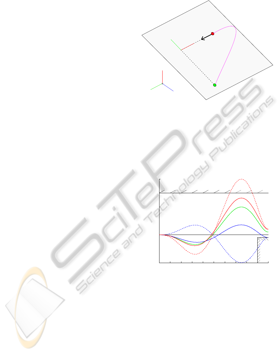
Figure 3: The above diagram shows the the change in co-
ordinate systems for the transportation DMPs. The axes
X
w
-Y
w
-Z
w
are the world coordinate system, while X
p
-Y
p
-Z
p
is the planar right handed coordinate system in which the
DMP is specified. The trajectory of the DMP is shown by
the pink line, starting at the green point, and ending at the
red point. Note that X
p
is parallel to the approach direc-
tion of the hand, which is shown by the black arrow a. The
planar axis Y
p
is perpendicular to X
p
, and pointing from the
motor primitive’s starting location s towards the goal g.
EFFECTS OF DMP AMPLITUDE a FACTOR
0 0.1 0.2 0.3 0.4 0.5 0.6 0.7 0.8 0.9 1
−0.05
0
0.05
0.1
Figure 4: This is a demonstration of the effects of augment-
ing the amplitude variable a of DMPs. The black lines rep-
resent boundaries. The green plot shows the trained trajec-
tory of the DMP going to 0.05, and is the same for all am-
plitude values. Now consider the scenario wherein the goal
is placed at 0.1, but the workspace is limited to ±0.75 (top
boundary). The dashed red line is the standard generaliza-
tion to a larger goal, while the red plot uses the new ampli-
tude. Notice how the new amplitude restricts the range of
the trajectory to the workspace. In a different scenario, we
move the goal to −0.05, but require the goal to be reached
from above (lower right boundary), e.g., a finger placed on a
surface. The dashed blue line is the standard generalization
to a negative goal, and the blue trajectory uses the new am-
plitude. Note that the trajectory is not flip in the case of the
new amplitude and thus stays within the restricted region.
Both of the new trajectories were generated with η = 0.25,
and maintain shapes close to that of the training trajectory.
ICINCO 2010 - 7th International Conference on Informatics in Control, Automation and Robotics
50
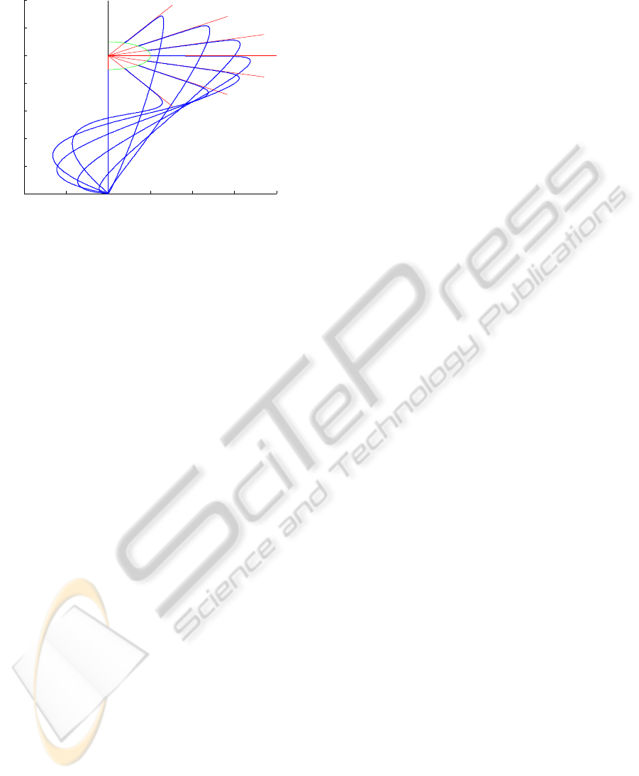
INTERPOLATION OF REACHING AROUND AN
OBJECT
−0.2 −0.1 0 0.1 0.2 0.3 0.4
0
0.2
0.4
0.6
0.8
1
1.2
1.4
Figure 5: The plot shows workspace trajectories, wherein
the x and y values are governed by two DMPs sharing a
canonical system. The red lines indicate the desired ap-
proach direction while the green semicircle indicates the
goal positions along them. The blue lines show the trajec-
tories for the different goals. They make use of the higher
level controller of Subsection 2.3, with η = 0.25. The ap-
proach direction DMP was trained on an amplitude of one.
ponents require to move around the outside of ob-
jects. In the standard form a = g − y
0
(Ijspeert et al.,
2003), which can lead to motions that easily exceed
the robot’s workspace if g ≈ y
0
during the training,
but not during the motion reproduction. The supervi-
sor can control these trajectories by scaling the shap-
ing force (see Appendix), and thus we propose the
amplitude term
a = kη(g− y
0
) + (1− η)(g
T
− y
0T
)k,
where g
T
and y
0T
are the goal and start positions
of the training data respectively, and η ∈ [0,1] is
a weighting hyperparameter. The resulting trajec-
tory amplitude is in the convex hull of the training
amplitude and the standard interpolation value (a =
g − y
0
) (Ijspeert et al., 2003) and thus only affects
how conservative the generalization to new points is,
as can be seen in Figure 4. By taking the absolute
value of the amplitude, the approach direction is not
reversed, giving a result similar to the use of a con-
stant amplitude proposed by Park et al. (Park et al.,
2008), which corresponds to the special case of η = 0.
Example interpolations of a transportation trajec-
tory can be seen in Figure 5.
3 GRASPING EXPERIMENTS
The methods described in Section 2 were imple-
mented and evaluated on a real robot platform. The
robot consists of a Videre stereo camera mounted on
a pan-tilt unit, a Barrett hand, and a Mitsubishi PA10
arm. The robot was given the task of grasping an ob-
ject amongst clutter using only an ECVD model of
the object. The results of these trials were then com-
pared to trials of the same grasps using other stan-
dard robotics methods for comparison. We hypothe-
size that our method will result in significantly more
successful grasps than the other methods.
3.1 Grasping Experiment Procedure
Before the robot can perform a grasping task, its mo-
tions must be initialized. Determining the finger goal
state and specifying the detractor fields introduces
several new hyperparameters that have simple geo-
metrical interpretations. For instance, h = 2[w l l]
T
,
where w and l are the width and length of the fin-
ger respectively. To reflect the human tendency to-
wards more precise movements during the last 30%
of a motion (Jeannerod, 2009), the strength function,
s(x), was set to give the highest strengths during the
first 70% of the motion for the transportation, and the
last 30% for the finger posture.
A VICON
TM
motion tracking system was used to
record the movements of a human test subject dur-
ing a grasping task, which used a different object to
the one used by the robot. As the reaching trajecto-
ries are encoded in task space rather than joint space,
the correspondence problem was not an issue for the
imitation learning. Similarly, the DMPs of the fin-
gers are homogeneous, which circumvents the corre-
spondence problem of mapping the five human fin-
gers onto the three fingers of the robot. The imita-
tion learning was performed using locally weighted
regression in the the X
p
-Y
p
-Z
p
coordinate system, as
proposed by Ijspeert et al. (Ijspeert et al., 2002).
Having defined the basic motions, the robot was
then given the task of grasping an object without hit-
ting surrounding obstacles (see Figure 1). Each trial
begins with an estimate of the pose of the object rela-
tive to the robot (Detry et al., 2008) and sets its grasp
location accordingly. The model’s ECVD are then
projected into the scene, and the robot attempts to
perform the grasp and lift the object 15cm so that it
is clear of the stand. The trial is a success if the robot
can detect the object in its hand at this point. If the
hand collides with an obstacle or knocks the object
down, the trial is marked as a failure. Grasps were
varied to include different approach directions and lo-
cations around the object. The experiment consisted
of 45 trials.
Two alternative approaches were compared with
our proposed method. The first represents a stan-
dard robotics approach of specifying a trajectory by
GRASPING WITH VISION DESCRIPTORS AND MOTOR PRIMITIVES
51
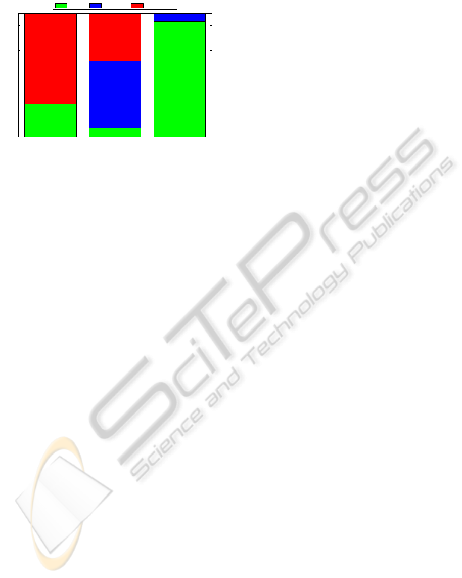
via points std. DMP ECVD DMP
0
0.1
0.2
0.3
0.4
0.5
0.6
0.7
0.8
0.9
1
Percentage of Trials
Success Object Coll. Obstacle Coll.
Figure 6: The occurrences of successes and collision types
for the different methods are shown. The first column
presents the results for the traditional robotics method of
specifying trajectories by via points. The second column
corresponds to using standard DMPs, while the final col-
umn incorporates the ECVD based potential field and su-
pervisory DMP controller. The occurrences are given as the
percentage of trials. Trials that collided multiple times, are
classified by their first collision.
straight lines between via points and uses fully ex-
tended fingers with no preshaping of the hand. The
other approach is to use standard DMPs learned from
the same human demonstrated movements as our pro-
posed methods, but without the proposed detractor
field and supervisory controller. The same grasp lo-
cations were proposed to the different methods, and
obstacles were placed in similar positions for the the
different trials to allow for a fair comparison between
the methods.
3.2 Experimental Results
From the three tested methods, the proposed method
acquired the highest success rate, as can be seen in
Figure 6. The task was not trivial, and all of the meth-
ods encountered both successes and problems during
the trials.
The standard DMP method encountered the most
problems (success rate of only 7%) a majority of
which were caused by collisions with the object. This
high failure rate can be attributed to the method not
specifically incorporating a desired approach direc-
tion. In successful trials, the approach direction was
close to that of the initial imitation learning. There-
fore the proposed DMP supervisor improved the gen-
eralization of the movement to new target grasps, and
the system would benefit from it even in uncluttered
environments. Similarly, the open-loop preshaping of
the hand helped avoid obstacles, but occasionally pre-
vented the hand from being sufficiently open to accept
the object. The proposed detractor field successfully
overcame this problem for the ECVD DMPs.
The via points method encountered no collisions
with the object, and would have worked well in an
uncluttered environment. The method still encoun-
tered collisions with the obstacles for 73% of the tri-
als, but this is more reflective of the difficulty of the
task rather than the via point method. The method
can therefore be considered as a good approach if it
were combined with a suitable path planning method
for obstacle avoidance. However, the path planner
would need additional information and assumptions
about the scene and possibly even extra hardware to
acquire it.
The proposed method had a success rate of 93%,
with no occurrences of collisions with obstacles. The
trials that did fail were the result of the object falling
down while the fingers were closing and thus do not
indicate problems with the approach used to reach-
ing the grasp location. The method does have certain
restrictions though. The magnitude of the detractor
fields needs to be calibrated based on the density of
ECVDs for common objects, but some obstacles en-
countered may present lower densities. As the current
set of ECVD relies on object edges, smooth objects
can lead to noisy or very sparse descriptors, and there-
fore not create a suitable basis for obstacle avoidance.
As the number of descriptor types increases (e.g., cor-
ner and plane descriptors), this will become less of a
problem. Occluded obstacles will also need to rely
on additional information (e.g., force feedback) to be
avoided, although this is a source of error for all vi-
sion based planners.
Given a few restrictions, the results still show that
our hypothesis was correct and the proposed methods
represent a suitable basis for avoiding obstacles with-
out relying on a complicated path planner and using
only a small amount of vision information compared
to standard robot systems.
4 CONCLUSIONS
The proposed methods augment dynamical system
motor primitives to incorporate Early Cognitive Vi-
sion descriptors by using a potential field. These
methods represent important tools that a robot needs
to reactively execute grasps of an object in a cluttered
environment without relying on a complex planner.
The techniques allow for preshaping the fingers to
match the shape and size of the object and curving
the trajectory of the hand around objects(Wank et al.,
2004). These modifications were tested on a real
robot, and it was discovered that the methods were
not only successful at performing the task, but also
ICINCO 2010 - 7th International Conference on Informatics in Control, Automation and Robotics
52

allowed for easier imitation learning, better interpola-
tion of the learned trajectories, and significantly better
chances of a success of a grasp in cluttered environ-
ments than standard motor primitives. Although the
experiments were performed within a grasping task
scenario, the proposed methods can be beneficial for
other manipulation tasks, such as pressing buttons and
pushing objects.
REFERENCES
Arimoto, S. (2008). Control Theory of Multi-fingered
Hands. Springer London.
Bard, C., Troccaz, J., and Vercelli, G. (1991). Shape analy-
sis and hand preshaping for grasping. In Proceedings
of IROS’91.
Bicchi, A. and Kumar, V. (2000). Robotic grasping and
contact: a review. In ICRA 2000 proceedings.
Bishop, C. M. (2006). Pattern Recognition and Machine
Learning. Springer.
Chieffi, S. and Gentilucci, M. (1993). Coordination be-
tween the transport and the grasp components during
prehension movements.
Detry, R., Kroemer, O., Popovic, M., Touati, Y., Baseski, E.,
Krueger, N., Peters, J., and Piater, J. (2009). Object-
specific grasp affordance densities. In ICDL.
Detry, R., Pugeault, N., and Piater, J. (2008). Probabilistic
pose recovery using learned hierarchical object mod-
els. In International Cognitive Vision Workshop.
Graziano, M. S. (2006). Progress in understanding spatial
coordinate systems in the primate brain. Neuron.
Hartley, R. and Zisserman, A. (2000). Multiple View Geom-
etry in Computer Vision. Cambridge University Press.
Hsiao, K., Nangeroni, P., Huber, M., Saxena, A., and Ng,
A. (2009). Reactive grasping using optical proximity
sensors. In ICRA 2009 Proceedings.
Iberall, T. (1987). Grasp planning for human prehension. In
Proceedings of ICAI’87.
Ijspeert, A. J., Nakanishi, J., , and Schaal, S. (2002). Move-
ment imitation with nonlinear dynamical systems in
humanoid robots. In ICRA.
Ijspeert, A. J., Nakanishi, J., , and Schaal, S. (2003). Learn-
ing attractor landscapes for learning motor primitives.
In NIPS.
Jeannerod, M. (1997). Perspectives of Motor Behaviour and
Its Neural Basis, chapter Grasping Objects: The Hand
as a Pattern Recognition Device.
Jeannerod, M. (2009). Sensorimotor Control of Grasping:
Physiology and Pathophysiology, chapter The study
of hand movements during grasping. A historical per-
spective. Cambridge University Press.
Krueger, N., Lappe, M., and Woergoetter, F. (2004). Bi-
ologically motivated multimodal processing of visual
primitives. The Interdisciplinary Journal of Artificial
Intelligence and the Simulation of Behaviour.
Oztop, E., Bradley, N. S., and Arbib, M. A. (2004). Infant
grasp learning: a computational model.
Oztop, E. and Kawato, M. (2009). Sensorimotor Control of
Grasping: Physiology and Pathophysiology, chapter
Models for the control of grasping. Cambridge Uni-
versity Press.
Park, D.-H., Hoffmann, H., Pastor, P., and Schaal, S.
(2008). Movement reproduction and obstacle avoid-
ance with dynamic movement primitives and poten-
tial fields. In IEEE International Conference on Hu-
manoid Robots(HUMANOIDS).
Pugeault, N. (2008). Early Cognitive Vision: Feedback
Mechanisms for the Disambiguation of Early Visual
Representation. Vdm Verlag Dr. Mueller.
Saxena, A., Dreimeyer, J., Kearns, J., Osondu, C., and Ng,
A. (2008). Experimental Robotics, chapter Learning
to Grasp Novel Objects using Vision. Springer Berlin.
Schaal, S., Peters, J., Nakanishi, J., and Ijspeert, A. (2003).
Learning movement primitives. In Proceedings of
ISRR’03.
Steffen, J., Haschke, R., and Ritter, H. (2007). Experience-
based and tactile-driven dynamic grasp control. In IRS
proceedings.
Wank, V., Fischer, A., Bos, K., Boesnach, I., Moldenhauer,
J., and Beth, T. (2004). Similarities and varieties in
human motiontrajectories of predefined grasping and
disposing movements. International Journal of Hu-
manoid Robotics.
APPENDIX
Dynamical Systems Motor Primitives
The dynamical systems motor primitives (DMPs) pro-
posed by Ijspeert et al. (Ijspeert et al., 2003) were in-
spired by the simple, but highly adaptive,motions that
animals employ,and combine to obtain more complex
motions. The primitives are implemented as a passive
dynamical system with an external force, and repre-
sented as
¨y = α
z
(β
z
τ
−2
(g− y) − τ
−1
˙y) + aτ
−2
f(x), (1)
where α
z
and β
z
are constants, τ controls the duration
of the primitive, a is an amplitude, f(x) is a nonlinear
function, and g is the goal for the state variable y.
By selecting α
z
and β
z
appropriately, and setting
a = 0, the system reduces to ¨y = α
z
(β
z
τ
2
(g− y) − τ˙y)
and becomes a critically damped global attractor. It
can be visualized as a spring and damper system that
ensures state y will always end at the goal value g.
The function f(x) is a shaping function based on
the state, x ∈ [0,1], of the canonical system that syn-
chronizes the DMPs ˙x = −α
x
τx, where α
x
is a time
GRASPING WITH VISION DESCRIPTORS AND MOTOR PRIMITIVES
53

constant. The function takes the form
f (x) =
∑
M
j=1
ψ
j
(x)w
j
x
∑
M
i=1
ψ
i
(x)
,
where M is the number of basis functions, ψ(x) are
Gaussian basis functions, and w are weights acquired
through locally weighted regression (Ijspeert et al.,
2003). This function has the effect of introducing a
non-linearity that can affect the spring-dampersystem
to output any arbitrary trajectory specified by the user.
Due to the dependence of f(x) on x, the shaping term
decays to zero with x, so that the spring and damper
beneficial properties of the attractor are maintained.
The resulting primitives can encode arbitrary tra-
jectories, and still ensure that the goal state is always
achieved. The trajectories can also be scaled in time
and space by setting the τ and g variables appropri-
ately and thus generalize to a range of situations.
Early Cognitive Vision System
The entire prehensile process effectively occurs be-
fore the hand has even touched the object and thus
the vision system plays a very important role (Bard
et al., 1991; Iberall, 1987). Our system uses the Early
CognitiveVision methods of Pugeault et al. (Pugeault,
2008; Hartley and Zisserman, 2000), which makes a
minimal number of assumptions about the object, and
has been successfully implemented to determine good
grasp locations (Detry et al., 2009). A principal idea
of this vision system is to store additional low level
information and perform perceptual grouping on it to
later aid the higher level stereo matching and 3D con-
structions.
The methods extract local features of a scene,
which it localizes and orientates in space (Krueger
et al., 2004). Each descriptor is a symbolic rep-
resentation for an edge in 3D. The resulting fea-
tures are called early cognitive vision descriptors
(ECVD) (Pugeault, 2008), and can be used in generat-
ing models of objects for pose estimation (Detry et al.,
2008), and for symbolically describing 3D scenes. By
using a large amount of small ECVDs, any arbitrary
object can be represented.
When performing a grasping task, the robot uses
a hierarchical Markov model of the object’s ECVD
geometry (Detry et al., 2008) to determine its pose,
which can then be used to superimpose the ECVDs
of the model back into the scene. The grasping tech-
niques can therefore use geometric information of a
partially occluded object.
ICINCO 2010 - 7th International Conference on Informatics in Control, Automation and Robotics
54
